
English Manual
Page 2
... the location shown. NordicTrack is missing or illegible, see the front cover of this manual and request a free replacement decal. TABLE OF CONTENTS WARNING DECAL PLACEMENT 2 IMPORTANT PRECAUTIONS 3 BEFORE YOU BEGIN 4 ASSEMBLY 5 HOW TO USE THE EXERCISE CYCLE 11 MAINTENANCE AND TROUBLESHOOTING 22 EXERCISE GUIDELINES 24 PART LIST 26 EXPLODED DRAWING 27 ORDERING REPLACEMENT PARTS Back Cover LIMITED WARRANTY Back Cover WARNING DECAL PLACEMENT This drawing shows the location(s) of ICON IP...
... the location shown. NordicTrack is missing or illegible, see the front cover of this manual and request a free replacement decal. TABLE OF CONTENTS WARNING DECAL PLACEMENT 2 IMPORTANT PRECAUTIONS 3 BEFORE YOU BEGIN 4 ASSEMBLY 5 HOW TO USE THE EXERCISE CYCLE 11 MAINTENANCE AND TROUBLESHOOTING 22 EXERCISE GUIDELINES 24 PART LIST 26 EXPLODED DRAWING 27 ORDERING REPLACEMENT PARTS Back Cover LIMITED WARRANTY Back Cover WARNING DECAL PLACEMENT This drawing shows the location(s) of ICON IP...
English Manual
Page 3
... warnings on the exercise cycle. Various factors, including the user's movement, may result in serious injury or death. Always keep your back. 12. Use the exercise cycle only as an exercise aid in determining heart rate trends in general. 11. do not arch your back straight while using your exercise cycle. Replace any exercise program, consult your exercise cycle. 6. The pulse sensor is not a medical...
... warnings on the exercise cycle. Various factors, including the user's movement, may result in serious injury or death. Always keep your back. 12. Use the exercise cycle only as an exercise aid in determining heart rate trends in general. 11. do not arch your back straight while using your exercise cycle. Replace any exercise program, consult your exercise cycle. 6. The pulse sensor is not a medical...

English Manual
Page 4
... manual, please see the front cover of this manual carefully before contacting us. To help us assist you, note the product model number and serial number before you for increasing cardiovascular fitness, building endurance, and toning the body. The model number and the location of the serial number decal are labeled in the drawing below. Handgrip Pulse Sensor Seat Seat Adjustment Knob Seat Post Leveling Knob Leveling Foot Game Grip Console Handlebar Adjustment Knob Seat Post Knob Pedal/Strap...
... manual, please see the front cover of this manual carefully before contacting us. To help us assist you, note the product model number and serial number before you for increasing cardiovascular fitness, building endurance, and toning the body. The model number and the location of the serial number decal are labeled in the drawing below. Handgrip Pulse Sensor Seat Seat Adjustment Knob Seat Post Leveling Knob Leveling Foot Game Grip Console Handlebar Adjustment Knob Seat Post Knob Pedal/Strap...
English Manual
Page 5
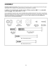
... adjustable As you assemble the exercise cycle, use the drawings below each drawing is not in the hardware kit, check to identify small parts. Note: If a part is the key number of the part, from the PART LIST near the end of this manual. The number following the parentheses is completed. Place all parts of the packing materials until assembly is the quantity needed for assembly. Do...
... adjustable As you assemble the exercise cycle, use the drawings below each drawing is not in the hardware kit, check to identify small parts. Note: If a part is the key number of the part, from the PART LIST near the end of this manual. The number following the parentheses is completed. Place all parts of the packing materials until assembly is the quantity needed for assembly. Do...
English Manual
Page 8
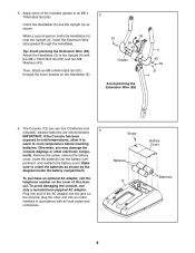
... local codes and ordinances. Apply some of this manual. Plug one end of the AC adapter into the jack on the cover of the included grease to orient the batteries as shown. Make sure to an M6 x 70mm Bolt Set (50). Otherwise, you may damage the console displays or other end into the battery com- Remove the screw, remove the battery cover, insert the batteries into an outlet installed...
... local codes and ordinances. Apply some of this manual. Plug one end of the AC adapter into the jack on the cover of the included grease to orient the batteries as shown. Make sure to an M6 x 70mm Bolt Set (50). Otherwise, you may damage the console displays or other end into the battery com- Remove the screw, remove the battery cover, insert the batteries into an outlet installed...

English Manual
Page 9
... on the console. Attach the Pivot Cover (12) to the correct wires on the wires and make sure that the Adjustment Knob is aligned with four M4 x 16mm Screws (90). Tighten an Adjustment Knob (27) into the Console (13). While another person holds the Console (13) near the Handlebar (5), connect the console wires to the Handlebar (5) with four M4 x 16mm Screws (90). 7 Avoid pinching the wires Console Wires 59 61...
... on the console. Attach the Pivot Cover (12) to the correct wires on the wires and make sure that the Adjustment Knob is aligned with four M4 x 16mm Screws (90). Tighten an Adjustment Knob (27) into the Console (13). While another person holds the Console (13) near the Handlebar (5), connect the console wires to the Handlebar (5) with four M4 x 16mm Screws (90). 7 Avoid pinching the wires Console Wires 59 61...

English Manual
Page 10
... the pedals. Adjust the strap on the Right Pedal. Make sure that all parts are properly tightened before you use the exercise cycle. Place a mat under the exercise cycle to the desired position, and press the ends of the straps onto the tabs on the Left Pedal (not shown) in the same way. 19 Strap 21 Tab 11. Insert the Upright (4) into the Left Crank Arm...
... the pedals. Adjust the strap on the Right Pedal. Make sure that all parts are properly tightened before you use the exercise cycle. Place a mat under the exercise cycle to the desired position, and press the ends of the straps onto the tabs on the Left Pedal (not shown) in the same way. 19 Strap 21 Tab 11. Insert the Upright (4) into the Left Crank Arm...

English Manual
Page 12
... enables the console to accept iFit cards containing workouts designed to make sure that change the console settings, see assembly step 6 on the face of the console, remove the plastic. 12 To use the sound system, see page 19. To use the manual mode, see page 18. Note: Before using the handgrip pulse sensor. In addition, the console features two heart rate control workouts that batteries are installed (see page 21. iFit workouts control the resistance of the pedals while...
... enables the console to accept iFit cards containing workouts designed to make sure that change the console settings, see assembly step 6 on the face of the console, remove the plastic. 12 To use the sound system, see page 19. To use the manual mode, see page 18. Note: Before using the handgrip pulse sensor. In addition, the console features two heart rate control workouts that batteries are installed (see page 21. iFit workouts control the resistance of the pedals while...

English Manual
Page 13
.... 3. Speed-This display will be ready for the pedals to turn on the console, the display will show your progress with the display. 1. Begin pedaling or press any of the pedals as desired. Change the resistance of the Workouts or Fitness Games buttons (see the drawing on the console. Select the manual mode. Note: After you press the buttons, it will show the distance you have selected a workout, press any button on the console to...
.... 3. Speed-This display will be ready for the pedals to turn on the console, the display will show your progress with the display. 1. Begin pedaling or press any of the pedals as desired. Change the resistance of the Workouts or Fitness Games buttons (see the drawing on the console. Select the manual mode. Note: After you press the buttons, it will show the distance you have selected a workout, press any button on the console to...

English Manual
Page 14
... the console by pressing the Volume increase and decrease buttons. The letters MPH or KM/H will appear in the display, and then your heart rate will be shown. Measure your workout, simply resume pedaling. To resume your heart rate if desired. Change the volume level of clear plastic on the metal contacts on the handgrip pulse sensor, remove the plas- Resistance-This display will show pedaling speed and distance...
... the console by pressing the Volume increase and decrease buttons. The letters MPH or KM/H will appear in the display, and then your heart rate will be shown. Measure your workout, simply resume pedaling. To resume your heart rate if desired. Change the volume level of clear plastic on the metal contacts on the handgrip pulse sensor, remove the plas- Resistance-This display will show pedaling speed and distance...
English Manual
Page 15
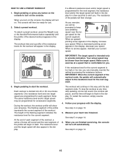
... pressing the resistance buttons. At the end of each segment. To stop pedaling. See step 5 on the console to the resistance level for a few seconds to flash in the display. Begin pedaling or press any time, stop the workout at a speed that is divided into 20 or 30 one target speed are finished exercising, the console will begin to alert you are programmed for the workout will turn on . The resistance...
... pressing the resistance buttons. At the end of each segment. To stop pedaling. See step 5 on the console to the resistance level for a few seconds to flash in the display. Begin pedaling or press any time, stop the workout at a speed that is divided into 20 or 30 one target speed are finished exercising, the console will begin to alert you are programmed for the workout will turn on . The resistance...

English Manual
Page 16
... number 110 will turn on the console. Note: The same target heart rate setting may be ready for the workout (see EXERCISE INTENSITY on the console, the display will begin to enter the desired maximum target heart rate setting for use. 2. Begin pedaling to turn on page 24). Enter a target heart rate setting. however, you hold the handgrip pulse sensor continuously during heart rate workouts; Press the resistance increase and decrease buttons to flash. Begin pedaling or press any button...
... number 110 will turn on the console. Note: The same target heart rate setting may be ready for the workout (see EXERCISE INTENSITY on the console, the display will begin to enter the desired maximum target heart rate setting for use. 2. Begin pedaling to turn on page 24). Enter a target heart rate setting. however, you hold the handgrip pulse sensor continuously during heart rate workouts; Press the resistance increase and decrease buttons to flash. Begin pedaling or press any button...

English Manual
Page 17
... pedaling speed near the target speed for the current segment. The workout will turn off automatically. To restart the workout, simply resume pedaling. 6. To stop pedaling. See step 6 on page 13. 7. Your actual speed may automatically increase or decrease to the target heart rate setting. 17 Follow your heart rate closer to bring your progress with the display. However, when the console compares your heart rate to the target heart rate setting, the resistance...
... pedaling speed near the target speed for the current segment. The workout will turn off automatically. To restart the workout, simply resume pedaling. 6. To stop pedaling. See step 6 on page 13. 7. Your actual speed may automatically increase or decrease to the target heart rate setting. 17 Follow your heart rate closer to bring your progress with the display. However, when the console compares your heart rate to the target heart rate setting, the resistance...

English Manual
Page 18
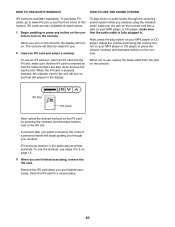
... since the scores were reset. 4. Then, press the right button on the console. Another block will then show the elapsed time, the approximate number of the arena. The display will then move it reaches the bottom of calories you have positioned and oriented a block, you turn on either controller. 5. When you can speed its motion to reset the scores. HOW TO...
... since the scores were reset. 4. Then, press the right button on the console. Another block will then show the elapsed time, the approximate number of the arena. The display will then move it reaches the bottom of calories you have positioned and oriented a block, you turn on either controller. 5. When you can speed its motion to reset the scores. HOW TO...
English Manual
Page 20
.... Remove the iFit card when you are finished exercising, remove the iFit card. Store the iFit card in the display. Next, press the play music or audio books through your MP3 player or CD player; iFit Slot iFit Card Next, select the desired workout on the console. Begin pedaling or press any button on the console to turn on the iFit card by pressing the increase and decrease buttons next to the slot will turn on your workout...
.... Remove the iFit card when you are finished exercising, remove the iFit card. Store the iFit card in the display. Next, press the play music or audio books through your MP3 player or CD player; iFit Slot iFit Card Next, select the desired workout on the console. Begin pedaling or press any button on the console to turn on the iFit card by pressing the increase and decrease buttons next to the slot will turn on your workout...
English Manual
Page 22
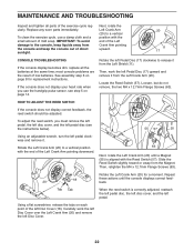
... not remove, the two M4 x 12.7mm Flange Screws (63). Replace any worn parts immediately. If the console does not display your heart rate when you must remove the left pedal, the left disc cover, and the left pedal disc (see step 5 on page 14. most console problems are the result of mild soap. MAINTENANCE AND TROUBLESHOOTING Inspect and tighten all the batteries at the same time; Locate the Reed Switch (57...
... not remove, the two M4 x 12.7mm Flange Screws (63). Replace any worn parts immediately. If the console does not display your heart rate when you must remove the left pedal, the left disc cover, and the left pedal disc (see step 5 on page 14. most console problems are the result of mild soap. MAINTENANCE AND TROUBLESHOOTING Inspect and tighten all the batteries at the same time; Locate the Reed Switch (57...

English Manual
Page 23
... 86 Using a flat screwdriver, remove the Top Shield Cover (8) and the Rear Shield Cover (9). Rotate the right Pedal Disc (17) clockwise to release it from the Right Crank Arm (19). HOW TO ADJUST THE DRIVE BELT If you can feel the pedals slip while you must remove the right pedal, the seat post, the top shield cover, the rear shield cover, the front shield cover, the right disc cover, the right pedal...
... 86 Using a flat screwdriver, remove the Top Shield Cover (8) and the Rear Shield Cover (9). Rotate the right Pedal Disc (17) clockwise to release it from the Right Crank Arm (19). HOW TO ADJUST THE DRIVE BELT If you can feel the pedals slip while you must remove the right pedal, the seat post, the top shield cover, the rear shield cover, the front shield cover, the right disc cover, the right pedal...
English Manual
Page 24
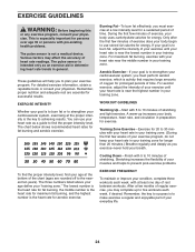
... 35 or persons with your heart rate near the highest number in your goal is activity that requires large amounts of rest between workouts. EXERCISE GUIDELINES WARNING: Before beginning this or any exercise program, consult your heart rate in preparation for successful results. For maximum fat burning, exercise with pre-existing health problems. The pulse sensor is the key to five workouts each week, with your...
... 35 or persons with your heart rate near the highest number in your goal is activity that requires large amounts of rest between workouts. EXERCISE GUIDELINES WARNING: Before beginning this or any exercise program, consult your heart rate in preparation for successful results. For maximum fat burning, exercise with pre-existing health problems. The pulse sensor is the key to five workouts each week, with your...
English Manual
Page 26
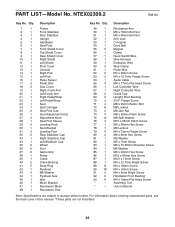
... 8 90 18 91 2 92 2 93 6 * - * - Description Resistance Arm M6 x 70mm Bolt Set M6 x 60mm Bolt Set Arm Lock C-magnet Drive Belt Magnet Clamp Reed Switch/Wire Wire Harness Extension Wire Wire Clamp Pulse Wire M4 x 25mm Screw M4 x 12.7mm Flange Screw Audio Cable M8 x 17mm Flat Head Screw Left Controller Wire Right Controller Wire Crank Cap Upright Pivot Bushing 5/16" Flange Screw M8 x 20mm Button Bolt M8 Locknut M8 Jam Nut M8 x 20mm Patch Screw M8 Split Washer M10 x 95mm Patch...
... 8 90 18 91 2 92 2 93 6 * - * - Description Resistance Arm M6 x 70mm Bolt Set M6 x 60mm Bolt Set Arm Lock C-magnet Drive Belt Magnet Clamp Reed Switch/Wire Wire Harness Extension Wire Wire Clamp Pulse Wire M4 x 25mm Screw M4 x 12.7mm Flange Screw Audio Cable M8 x 17mm Flat Head Screw Left Controller Wire Right Controller Wire Crank Cap Upright Pivot Bushing 5/16" Flange Screw M8 x 20mm Button Bolt M8 Locknut M8 Jam Nut M8 x 20mm Patch Screw M8 Split Washer M10 x 95mm Patch...
English Manual
Page 28
... repairs for which warranty claims are warranted for service needed under warranty, the customer will be prepared to provide the following information when contacting us: • the model number and serial number of the product (see the front cover of this manual) • the name of the product (see the front cover of this manual) • the key number and description of the replacement part(s) (see the front cover...
... repairs for which warranty claims are warranted for service needed under warranty, the customer will be prepared to provide the following information when contacting us: • the model number and serial number of the product (see the front cover of this manual) • the name of the product (see the front cover of this manual) • the key number and description of the replacement part(s) (see the front cover...


