Product Manual
Page 25
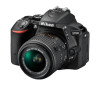
... rest of the manual. You may find it helpful to bookmark this section and refer to familiarize yourself with camera controls and displays. The Camera Body 67 5 8 4 3 9 19 2 10 1 11 12 13 18 17 16 15 14 1 AF-assist illuminator 81, 250 11 Fn button 265 Self-timer lamp 76 12..., 174 17 CPU contacts 7 Mode dial 4 18 Infrared receiver for ML-L3 remote 8 Built-in flash 93 control (front 108 9 M/ Y button 93, 95, 131 19 Body cap 10 Eyelets for camera strap 27 Introduction 1
... rest of the manual. You may find it helpful to bookmark this section and refer to familiarize yourself with camera controls and displays. The Camera Body 67 5 8 4 3 9 19 2 10 1 11 12 13 18 17 16 15 14 1 AF-assist illuminator 81, 250 11 Fn button 265 Self-timer lamp 76 12..., 174 17 CPU contacts 7 Mode dial 4 18 Infrared receiver for ML-L3 remote 8 Built-in flash 93 control (front 108 9 M/ Y button 93, 95, 131 19 Body cap 10 Eyelets for camera strap 27 Introduction 1

Product Manual
Page 31
D Using the Monitor Rotate the monitor gently within the limits shown. To protect the monitor when the camera is not in use force. Failure to observe this precaution could damage the camera or monitor. Failure to observe these precautions could damage the camera. Do not lift or carry the camera by the monitor. Introduction 7 Do not use , fold it back face down against the camera body.
D Using the Monitor Rotate the monitor gently within the limits shown. To protect the monitor when the camera is not in use force. Failure to observe this precaution could damage the camera or monitor. Failure to observe these precautions could damage the camera. Do not lift or carry the camera by the monitor. Introduction 7 Do not use , fold it back face down against the camera body.
Product Manual
Page 53
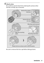
Introduction 29 Be careful to remove the lens cap before taking pictures. Remove the camera body cap Remove the rear lens cap Mounting mark (camera) Align the mounting marks Mounting mark (lens) Rotate the lens as shown until it clicks into place Be sure to prevent dust from entering the camera when the lens or body cap is removed. 4 Attach a lens.
Introduction 29 Be careful to remove the lens cap before taking pictures. Remove the camera body cap Remove the rear lens cap Mounting mark (camera) Align the mounting marks Mounting mark (lens) Rotate the lens as shown until it clicks into place Be sure to prevent dust from entering the camera when the lens or body cap is removed. 4 Attach a lens.

Product Manual
Page 61
... not in use, press and hold the lens release button (q) while turning the lens clockwise (w). After removing the lens, replace the lens caps and camera body cap.
... not in use, press and hold the lens release button (q) while turning the lens clockwise (w). After removing the lens, replace the lens caps and camera body cap.

Product Manual
Page 63
... focal lengths to zoom in the Viewfinder 1 Ready the camera. Zoom in If the lens is equipped with your right hand and cradle the camera body or lens with a retractable lens barrel button (0 30), press and hold the button while rotating the zoom ring until the lens is released and the...
... focal lengths to zoom in the Viewfinder 1 Ready the camera. Zoom in If the lens is equipped with your right hand and cradle the camera body or lens with a retractable lens barrel button (0 30), press and hold the button while rotating the zoom ring until the lens is released and the...

Product Manual
Page 69
When framing photographs in your right hand and cradle the camera body or lens with your left. Live view switch 2 Ready the camera. "Point-and-Shoot" Modes (i and j) 45 Hold the handgrip in portrait (tall) orientation, hold the camera as shown at right. Framing Photos in the Monitor 1 Rotate the live view). The view through the lens will be displayed in the camera monitor (live view switch.
When framing photographs in your right hand and cradle the camera body or lens with your left. Live view switch 2 Ready the camera. "Point-and-Shoot" Modes (i and j) 45 Hold the handgrip in portrait (tall) orientation, hold the camera as shown at right. Framing Photos in the Monitor 1 Rotate the live view). The view through the lens will be displayed in the camera monitor (live view switch.

Product Manual
Page 74
Press the shutter-release button halfway to focus. 50 "Point-and-Shoot" Modes (i and j) Focus point The view through the lens is displayed in your right hand and cradle the camera body or lens with your left. 3 Focus. Live view switch 2 Ready the camera. Hold the handgrip in the monitor. Recording Movies Movies can be recorded in live view mode. 1 Rotate the live view switch.
Press the shutter-release button halfway to focus. 50 "Point-and-Shoot" Modes (i and j) Focus point The view through the lens is displayed in your right hand and cradle the camera body or lens with your left. 3 Focus. Live view switch 2 Ready the camera. Hold the handgrip in the monitor. Recording Movies Movies can be recorded in live view mode. 1 Rotate the live view switch.
Product Manual
Page 113
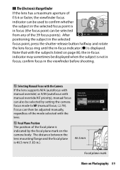
... A/M (autofocus with manual override/AF priority), manual focus can then be adjusted manually, regardless of the mode selected with the subjects listed on the camera body. A Focal Plane Position The position of the focal plane is indicated by setting the camera focus mode to confirm whether the subject in the selected...
... A/M (autofocus with manual override/AF priority), manual focus can then be adjusted manually, regardless of the mode selected with the subjects listed on the camera body. A Focal Plane Position The position of the focal plane is indicated by setting the camera focus mode to confirm whether the subject in the selected...
Product Manual
Page 338
... NIKKOR - z9 z z z - ✔ z1 1 Spot metering meters selected focus point (0 125). 2 The tilt knob for the PC-E NIKKOR 24mm f/3.5D ED may contact the camera body when the lens is not supported with AF-S and AF-I . Autofocus is revolved. 314 Technical Notes z8 z z z - ✔ z1 AI-P NIKKOR -
... NIKKOR - z9 z z z - ✔ z1 1 Spot metering meters selected focus point (0 125). 2 The tilt knob for the PC-E NIKKOR 24mm f/3.5D ED may contact the camera body when the lens is not supported with AF-S and AF-I . Autofocus is revolved. 314 Technical Notes z8 z z z - ✔ z1 AI-P NIKKOR -
Product Manual
Page 356
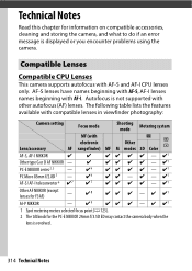
...(0 109, 282): The WR-1 can be released remotely by another WR-1 or a WR-R10 or WR-T10 wireless remote controller. Software Body cap Remote controls/ wireless remote controller Camera Control Pro 2: Control the camera remotely from a computer to record movies and photographs and save photographs... to the right (q), insert a fingernail into the gap and open the battery chamber (w). Body Cap BF-1B/Body Cap BF-1A: The body cap keeps the mirror, viewfinder screen, and image sensor free of Nikon software; For example, a WR-1 can function as a transmitter. 332 Technical Notes A ...
...(0 109, 282): The WR-1 can be released remotely by another WR-1 or a WR-R10 or WR-T10 wireless remote controller. Software Body cap Remote controls/ wireless remote controller Camera Control Pro 2: Control the camera remotely from a computer to record movies and photographs and save photographs... to the right (q), insert a fingernail into the gap and open the battery chamber (w). Body Cap BF-1B/Body Cap BF-1A: The body cap keeps the mirror, viewfinder screen, and image sensor free of Nikon software; For example, a WR-1 can function as a transmitter. 332 Technical Notes A ...

Product Manual
Page 361
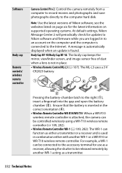
... to prevent the discharge of over 60% • are next to equipment that : • are easily damaged. If using the camera at the beach Camera body or seaside, wipe off sand or salt with care. When removing fingerprints and other foreign matter inside the camera may cause damage not covered under...
... to prevent the discharge of over 60% • are next to equipment that : • are easily damaged. If using the camera at the beach Camera body or seaside, wipe off sand or salt with care. When removing fingerprints and other foreign matter inside the camera may cause damage not covered under...

Product Manual
Page 365
Remove any dust and lint from the sensor with a blower can only be lowered after about two minutes. Replace the lens or body cap. Technical Notes 341 Dirt that light falls on the image sensor, examine the interior of the camera for dust or lint. A Use a Reliable Power ... while the mirror is raised, a beep will sound and the self-timer lamp will flash to warn that the shutter curtain will be removed by Nikon-authorized service personnel. Under no foreign objects are present, proceed to the down position and the shutter curtain will close and the mirror will close...
Remove any dust and lint from the sensor with a blower can only be lowered after about two minutes. Replace the lens or body cap. Technical Notes 341 Dirt that light falls on the image sensor, examine the interior of the camera for dust or lint. A Use a Reliable Power ... while the mirror is raised, a beep will sound and the self-timer lamp will flash to warn that the shutter curtain will be removed by Nikon-authorized service personnel. Under no foreign objects are present, proceed to the down position and the shutter curtain will close and the mirror will close...
Product Manual
Page 366
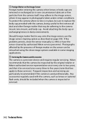
...to first remove all dust and other foreign matter that fees apply to two years, and that it may be adhering to replace the body cap provided with the camera, such as described on page 338. Any accessories regularly used professionally. If the problem persists, clean the ...sensor manually (0 340) or have the sensor cleaned by the original retailer or Nikon-authorized service representative once every one to these services). Nikon recommends that the camera be inspected by authorized Nikon service personnel. To protect the camera when no lens is a precision device and requires ...
...to first remove all dust and other foreign matter that fees apply to two years, and that it may be adhering to replace the body cap provided with the camera, such as described on page 338. Any accessories regularly used professionally. If the problem persists, clean the ...sensor manually (0 340) or have the sensor cleaned by the original retailer or Nikon-authorized service representative once every one to these services). Nikon recommends that the camera be inspected by authorized Nikon service personnel. To protect the camera when no lens is a precision device and requires ...

Product Manual
Page 368
... prevent fire. See "Image Sensor Cleaning" (0 338, 340) for an extended period, remove the battery to prevent discharge of liquid. Cleaning: When cleaning the camera body, use a blower to gently remove dust and lint, then wipe gently with cleaning tools, or subject it to powerful air currents from the lens, apply...
... prevent fire. See "Image Sensor Cleaning" (0 338, 340) for an extended period, remove the battery to prevent discharge of liquid. Cleaning: When cleaning the camera body, use a blower to gently remove dust and lint, then wipe gently with cleaning tools, or subject it to powerful air currents from the lens, apply...

Product Manual
Page 396
...camera with a fully-charged battery. • Nikon reserves the right to change the specifications of the hardware and software described in this manual may result from any mistakes that this manual at any time and without body cap; requires EP-5A power connector (available ...× 70 mm (4.9 × 3.9 × 2.8 in conformity with battery and memory card but without prior notice. approx. 420 g/14.9 oz (camera body only) Operating environment Temperature 0 °C-40 °C (+32 °F-104 °F) Humidity 85% or less (no condensation) • Unless otherwise stated, ...
...camera with a fully-charged battery. • Nikon reserves the right to change the specifications of the hardware and software described in this manual may result from any mistakes that this manual at any time and without body cap; requires EP-5A power connector (available ...× 70 mm (4.9 × 3.9 × 2.8 in conformity with battery and memory card but without prior notice. approx. 420 g/14.9 oz (camera body only) Operating environment Temperature 0 °C-40 °C (+32 °F-104 °F) Humidity 85% or less (no condensation) • Unless otherwise stated, ...

Product Manual
Page 419
... lock 127 Autofocus 78-87, 164-167 Auto-servo AF 78 Available settings 348 B Battery 27, 330, 373 Beep options 276 Black-and-white 299 Body cap 1, 332 Border (PictBridge 215 Bracketing 148, 264 Built-in AF-assist illuminator.81, 250, 318 Built-in flash 93, 320 Bulb 121 Burst 72...
... lock 127 Autofocus 78-87, 164-167 Auto-servo AF 78 Available settings 348 B Battery 27, 330, 373 Beep options 276 Black-and-white 299 Body cap 1, 332 Border (PictBridge 215 Bracketing 148, 264 Built-in AF-assist illuminator.81, 250, 318 Built-in flash 93, 320 Bulb 121 Burst 72...

Users Manual
Page 2
... sure all items listed here were included with your camera. ❏ Camera ❏ EN-EL15b rechargeable Li-ion battery with terminal cover ❏ BF-1B body cap ❏ MH-25a battery charger (comes with either an AC wall adapter or power cable of a type and shape that varies with the country...
... sure all items listed here were included with your camera. ❏ Camera ❏ EN-EL15b rechargeable Li-ion battery with terminal cover ❏ BF-1B body cap ❏ MH-25a battery charger (comes with either an AC wall adapter or power cable of a type and shape that varies with the country...

Users Manual
Page 6
... Contents ii About This Manual iv Menu List ix For Your Safety xv Notices ...xxi Getting to Know the Camera 1 Parts of the Camera 1 Camera Body 1 The Control Panel 7 The Viewfinder 8 The Live View Displays (Photos/Movies 11 The G Button 13 First Steps 19 Readying the Camera 19 Attaching the Strap...
... Contents ii About This Manual iv Menu List ix For Your Safety xv Notices ...xxi Getting to Know the Camera 1 Parts of the Camera 1 Camera Body 1 The Control Panel 7 The Viewfinder 8 The Live View Displays (Photos/Movies 11 The G Button 13 First Steps 19 Readying the Camera 19 Attaching the Strap...

Users Manual
Page 25
Getting to Know the Camera Parts of the Camera Camera Body 78 9 10 11 6 12 5 4 5 3 13 2 14 1 15 1 Accessory shoe (for optional 8 S (Q) button flash unit) 9 Sub-command dial 2 Release mode dial 10 Power switch 3 Release mode dial lock release 11 Shutter-release button (0 34) 4 Mode dial lock release 12 E button 5 Eyelet for camera strap (0 19) 13 E (focal plane mark) 6 Mode dial 14 Main command dial 7 Movie-record button (0 43) 15 Control panel (0 7) Getting to Know the Camera 1
Getting to Know the Camera Parts of the Camera Camera Body 78 9 10 11 6 12 5 4 5 3 13 2 14 1 15 1 Accessory shoe (for optional 8 S (Q) button flash unit) 9 Sub-command dial 2 Release mode dial 10 Power switch 3 Release mode dial lock release 11 Shutter-release button (0 34) 4 Mode dial lock release 12 E button 5 Eyelet for camera strap (0 19) 13 E (focal plane mark) 6 Mode dial 14 Main command dial 7 Movie-record button (0 43) 15 Control panel (0 7) Getting to Know the Camera 1

Users Manual
Page 27
9 8 7 6 1 CPU contacts 2 Lens mount (0 23) 3 Tripod socket 4 AF coupling 5 Fn button 1 2 10 54 3 6 Battery-chamber cover 7 Battery-chamber cover latch 8 Memory card slot cover (0 25) 9 Pv button 10 Body cap (0 23) Getting to Know the Camera 3
9 8 7 6 1 CPU contacts 2 Lens mount (0 23) 3 Tripod socket 4 AF coupling 5 Fn button 1 2 10 54 3 6 Battery-chamber cover 7 Battery-chamber cover latch 8 Memory card slot cover (0 25) 9 Pv button 10 Body cap (0 23) Getting to Know the Camera 3


