
User Manual
Page 2
... of Nickel-Cadmium Batteries. . 27 Intrinsically Safe Radio Information . . . . . 27 FMRC Approved Equipment 27 Repair of FMRC Approved Products . . . . 29 Limited Warranty 31 Accessories 35 Carry Cases 35 Chargers 35 Headsets 36 Remote Speaker Microphones 36 Adapters 36 Batteries 36 Antennas 36 COMPUTER SOFTWARE COPYRIGHTS The Motorola products described in this manual may include...
... of Nickel-Cadmium Batteries. . 27 Intrinsically Safe Radio Information . . . . . 27 FMRC Approved Equipment 27 Repair of FMRC Approved Products . . . . 29 Limited Warranty 31 Accessories 35 Carry Cases 35 Chargers 35 Headsets 36 Remote Speaker Microphones 36 Adapters 36 Batteries 36 Antennas 36 COMPUTER SOFTWARE COPYRIGHTS The Motorola products described in this manual may include...

User Manual
Page 36
... Remote Speaker Microphone AAHMN9053_ Noise-Cancelling Remote Speaker Microphone AAHMN9054_ Public Safety Remote Speaker Microphone ADAPTERS HLN9716_ Adapter for Audio Accessories HLN9717_ Adapter for the 3.5mm Audio Accessories AAHLN9718_ Vehicular Adapter ANTENNAS NAB6064_ PMAD4012_ PMAD4013_ PMAD4014_ PMAD4015_ HAD9743_ PMAD4023_ PMAD4025_ PMAE4002_ PMAE4003_ NAE6483AR PMAE4006_ PMAE4007_ PMAE4008_ Lowband, Heliflex VHF 136-155 MHz 9 cm, Stubby VHF 155...
... Remote Speaker Microphone AAHMN9053_ Noise-Cancelling Remote Speaker Microphone AAHMN9054_ Public Safety Remote Speaker Microphone ADAPTERS HLN9716_ Adapter for Audio Accessories HLN9717_ Adapter for the 3.5mm Audio Accessories AAHLN9718_ Vehicular Adapter ANTENNAS NAB6064_ PMAD4012_ PMAD4013_ PMAD4014_ PMAD4015_ HAD9743_ PMAD4023_ PMAD4025_ PMAE4002_ PMAE4003_ NAE6483AR PMAE4006_ PMAE4007_ PMAE4008_ Lowband, Heliflex VHF 136-155 MHz 9 cm, Stubby VHF 155...

Service Manual
Page 4
... Top Reassembly 3-10 3.7.2 PTT Reassembly 3-10 3.7.3 Speaker, Microphone, and Universal Connector Flex Reassembly ....... 3-10 3.7.4 Keypad, Display, and Keypad/PassPort/Option Board Reassembly...... 3-10 3.7.5 Chassis Assembly Reassembly 3-11 3.7.6 Chassis and Front Cover Reassembly 3-11 3.7.7 DTMF Retrofit Kit Procedure (Optional Upgrade Procedure 3-12 3.7.8 Option Board Installation 3-13 3.8 HT750 Radio Exploded Mechanical View and Parts List 3-15...
... Top Reassembly 3-10 3.7.2 PTT Reassembly 3-10 3.7.3 Speaker, Microphone, and Universal Connector Flex Reassembly ....... 3-10 3.7.4 Keypad, Display, and Keypad/PassPort/Option Board Reassembly...... 3-10 3.7.5 Chassis Assembly Reassembly 3-11 3.7.6 Chassis and Front Cover Reassembly 3-11 3.7.7 DTMF Retrofit Kit Procedure (Optional Upgrade Procedure 3-12 3.7.8 Option Board Installation 3-13 3.8 HT750 Radio Exploded Mechanical View and Parts List 3-15...

Service Manual
Page 6
...Error Codes - PassPort 6-3 6.4 Operation Display Codes 6-3 Chapter 7 Accessories 7-1 7.1 HT750/HT1250/HT1250•LS/HT1250•LS+/HT1550•XLS/MTX850/MTX950/ MTX850•...Speaker Microphones 7-5 7.1.13 Manuals 7-5 7.1.14 Retrofit Front Cover Kits 7-5 Chapter 8 Model Chart and Test Specifications 8-1 8.1 UHF 403-470 MHz (Conventional 8-1 8.2 UHF 450-512 MHz (Conventional 8-2 8.3 UHF 403-470 MHz (LTR and PassPort 8-3 8.4 UHF 450-512 MHz (LTR and PassPort 8-4 8.5 UHF 403-470 MHz (Conventional/LTR 8-5 8.6 UHF 450-512 MHz (Conventional/LTR 8-6 8.7 VHF 136-174 MHz 8-7 8.8 VHF...
...Error Codes - PassPort 6-3 6.4 Operation Display Codes 6-3 Chapter 7 Accessories 7-1 7.1 HT750/HT1250/HT1250•LS/HT1250•LS+/HT1550•XLS/MTX850/MTX950/ MTX850•...Speaker Microphones 7-5 7.1.13 Manuals 7-5 7.1.14 Retrofit Front Cover Kits 7-5 Chapter 8 Model Chart and Test Specifications 8-1 8.1 UHF 403-470 MHz (Conventional 8-1 8.2 UHF 450-512 MHz (Conventional 8-2 8.3 UHF 403-470 MHz (LTR and PassPort 8-3 8.4 UHF 450-512 MHz (LTR and PassPort 8-4 8.5 UHF 403-470 MHz (Conventional/LTR 8-5 8.6 UHF 450-512 MHz (Conventional/LTR 8-6 8.7 VHF 136-174 MHz 8-7 8.8 VHF...
Service Manual
Page 9
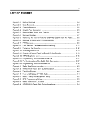
...Remove Retainer 3-7 Figure 3-5: Removing the Keypad Retainer and Other Boards from the Radio........ 3-8 Figure 3-6: Removal Speaker-Microphone Assembly 3-9 Figure 3-7: PTT Removal 3-9 Figure 3-8: Lock Retainer Catches to the Radio's Body 3-11 Figure 3-9: Fastening the Chassis 3-12 Figure 3-10: Activating ...the Retrofit 3-12 Figure 3-11: Changing Keypad/PassPort Board /Option Boards 3-13 Figure 3-12: HT750...
...Remove Retainer 3-7 Figure 3-5: Removing the Keypad Retainer and Other Boards from the Radio........ 3-8 Figure 3-6: Removal Speaker-Microphone Assembly 3-9 Figure 3-7: PTT Removal 3-9 Figure 3-8: Lock Retainer Catches to the Radio's Body 3-11 Figure 3-9: Fastening the Chassis 3-12 Figure 3-10: Activating ...the Retrofit 3-12 Figure 3-11: Changing Keypad/PassPort Board /Option Boards 3-13 Figure 3-12: HT750...

Service Manual
Page 23
.... General Since these radios may be performed only if necessary: section 3.6.2 Chassis Assembly/Disassembly on page 3-6 section 3.6.3 Keypad, Display, and Keypad/PassPort/Option Board Disassembly on page 3-6 section 3.6.4 Speaker, Microphone, and Universal Connector... Flex Disassembly on page 3-8 section 3.6.5 PTT Disassembly on page 3-9 section 3.6.6 Control Top Disassembly on page 3-9 section 3.7.7 DTMF Retrofit Kit Procedure (Optional Upgrade Procedure) on page 3-12 section 3.7.8 Option Board Installation on page 1-3 for shorts due to a Motorola...
.... General Since these radios may be performed only if necessary: section 3.6.2 Chassis Assembly/Disassembly on page 3-6 section 3.6.3 Keypad, Display, and Keypad/PassPort/Option Board Disassembly on page 3-6 section 3.6.4 Speaker, Microphone, and Universal Connector... Flex Disassembly on page 3-8 section 3.6.5 PTT Disassembly on page 3-9 section 3.6.6 Control Top Disassembly on page 3-9 section 3.7.7 DTMF Retrofit Kit Procedure (Optional Upgrade Procedure) on page 3-12 section 3.7.8 Option Board Installation on page 1-3 for shorts due to a Motorola...

Service Manual
Page 27
.... (This is attached to the process for the four remaining retainer arm tabs. Do not cut, bend, or pinch the heat seal. Speaker-Microphone Flex Circuit Tail Flat Blade Screwdriver Keypad Retainer Arm Tabs (4) Retainer Top Hooks Retainer Figure 3-6: Remove Retainer 4. Repeat this procedure for releasing...cover with a double-sided adhesive pad. Note that the two "top hooks" are still held underneath the front cover-right below the speaker. Insert the tip of a "penknife size," flat blade screwdriver in the opening at the end of tools. Display modules contain CMOS ...
.... (This is attached to the process for the four remaining retainer arm tabs. Do not cut, bend, or pinch the heat seal. Speaker-Microphone Flex Circuit Tail Flat Blade Screwdriver Keypad Retainer Arm Tabs (4) Retainer Top Hooks Retainer Figure 3-6: Remove Retainer 4. Repeat this procedure for releasing...cover with a double-sided adhesive pad. Note that the two "top hooks" are still held underneath the front cover-right below the speaker. Insert the tip of a "penknife size," flat blade screwdriver in the opening at the end of tools. Display modules contain CMOS ...

Service Manual
Page 28
...on page 3-15). 4. Peel-off the universal connector escutcheon label. Pull the rubber microphone boot from the Radio NOTE: At this assembly, you slide it in the boot. NOTE: The speaker-microphone assembly flex circuit goes through its pocket. To replace this point, the Option Board ...dustcover counterclockwise with a two-legged retainer bracket. If disassembly of the speaker-microphone assembly is held ) backer board away from the front cover, and remove the universal connector tail of the radio until you must peel-off the universal connector flex circuit escutcheon (label)....
...on page 3-15). 4. Peel-off the universal connector escutcheon label. Pull the rubber microphone boot from the Radio NOTE: At this assembly, you slide it in the boot. NOTE: The speaker-microphone assembly flex circuit goes through its pocket. To replace this point, the Option Board ...dustcover counterclockwise with a two-legged retainer bracket. If disassembly of the speaker-microphone assembly is held ) backer board away from the front cover, and remove the universal connector tail of the radio until you must peel-off the universal connector flex circuit escutcheon (label)....

Service Manual
Page 29
Universal Connector Tail Speaker Speaker Orientation Tab (12:00 Position) Microphone Boot Microphone Speaker Microphone Flex Circuit Assembly Figure 3-6: Removal Speaker-Microphone Assembly 3.6.5 PTT Disassembly If required, the PTT bezel and the PTT seal assembly can be ...lift it against the control top escutcheon. After the universal connector tail of the speaker-microphone assembly is removed from the bezel without the use of the boot. Maintenance 3-9 6. When reassembling the microphone in the front cover. 3. Remove the integrated control top seal, emergency button...
Universal Connector Tail Speaker Speaker Orientation Tab (12:00 Position) Microphone Boot Microphone Speaker Microphone Flex Circuit Assembly Figure 3-6: Removal Speaker-Microphone Assembly 3.6.5 PTT Disassembly If required, the PTT bezel and the PTT seal assembly can be ...lift it against the control top escutcheon. After the universal connector tail of the speaker-microphone assembly is removed from the bezel without the use of the boot. Maintenance 3-9 6. When reassembling the microphone in the front cover. 3. Remove the integrated control top seal, emergency button...

Service Manual
Page 30
...from a new control top escutcheon and place it becomes fully engaged. 3.7.3 Speaker, Microphone, and Universal Connector Flex Reassembly 1. NOTE: Pull the speaker-microphone flex circuit out of the radio until it in the recess in the top slot inside the front cover to... way during reassembly. 4. Insert the "top hooks" of the speaker-microphone flex assembly through the opening in paragraph 3-8). 2. Reinsert the microphone and boot into the slots below the speaker. 6. 3-10 Maintenance 3.7 Detailed Radio Reassembly 3.7.1 Control Top Reassembly 1. NOTE: Look inside the front ...
...from a new control top escutcheon and place it becomes fully engaged. 3.7.3 Speaker, Microphone, and Universal Connector Flex Reassembly 1. NOTE: Pull the speaker-microphone flex circuit out of the radio until it in the recess in the top slot inside the front cover to... way during reassembly. 4. Insert the "top hooks" of the speaker-microphone flex assembly through the opening in paragraph 3-8). 2. Reinsert the microphone and boot into the slots below the speaker. 6. 3-10 Maintenance 3.7 Detailed Radio Reassembly 3.7.1 Control Top Reassembly 1. NOTE: Look inside the front ...

Service Manual
Page 36
... Description Backup Battery Screw Contact, Finger (For UHF) Ctrl/RF Board Assembly Flex, Keypad/Controller Insulator, Antenna Pad, Thermal Seal, Contact Label, Warning Gasket, O-Ring Contact, Ground (For VHF) Chassis Shroud, Chassis Battery Beltclip HT1550•XLS Parts List (Continued) Item Motorola Part Number 30 6062884K01 31 0304726J04 32 3980667Z01...FM Keypad, Side Control Bezel, Side Control Keypad Keypad Board Assembly LCD Module Pad, Retainer Front Retainer, Keypad Board Pad, Retainer Back Felt, Speaker Felt, Mic Boot, Mic Speaker Microphone Flex, Univ Conn Cap, 33pF Retainer...
... Description Backup Battery Screw Contact, Finger (For UHF) Ctrl/RF Board Assembly Flex, Keypad/Controller Insulator, Antenna Pad, Thermal Seal, Contact Label, Warning Gasket, O-Ring Contact, Ground (For VHF) Chassis Shroud, Chassis Battery Beltclip HT1550•XLS Parts List (Continued) Item Motorola Part Number 30 6062884K01 31 0304726J04 32 3980667Z01...FM Keypad, Side Control Bezel, Side Control Keypad Keypad Board Assembly LCD Module Pad, Retainer Front Retainer, Keypad Board Pad, Retainer Back Felt, Speaker Felt, Mic Boot, Mic Speaker Microphone Flex, Univ Conn Cap, 33pF Retainer...

Service Manual
Page 65
...•LS Basic Service Manual English 7.1.14 Retrofit Front Cover Kits HLN9984 DTMF Retrofit Kit (HT750 only) - 16 Channel Model Only FM Approved AAHMN9054 UHF Public Safety Microphone Remote Speaker (450-470 MHz Only) - Accessories 7-5 7.1.11 Option Boards* (All option boards below...Voice Storage Option Board with Manual 6881088C22 Voice Storage User Manual AAENLN4150* Mandown board for Standard and Noise Cancelling AAHKN9057 VHF Public Safety Speaker Microphone with manual (148-174 MHz Only) - FM Approved AAHKN9055 Replacement Cable for HT1250 *All option boards include ...
...•LS Basic Service Manual English 7.1.14 Retrofit Front Cover Kits HLN9984 DTMF Retrofit Kit (HT750 only) - 16 Channel Model Only FM Approved AAHMN9054 UHF Public Safety Microphone Remote Speaker (450-470 MHz Only) - Accessories 7-5 7.1.11 Option Boards* (All option boards below...Voice Storage Option Board with Manual 6881088C22 Voice Storage User Manual AAENLN4150* Mandown board for Standard and Noise Cancelling AAHKN9057 VHF Public Safety Speaker Microphone with manual (148-174 MHz Only) - FM Approved AAHKN9055 Replacement Cable for HT1250 *All option boards include ...


