User Manual
Page 1
CONTENTS Computer Software Copyrights 2 Radio Overview 3 Parts of the Radio 3 HT750 Model 3 On/Off/Volume Knob 4 Channel Selector Knob 4 LED Indicator 4 Programmable Buttons 4 Push-to-Talk (PTT) Button 6 Microphone 6 Keypad Keys (for radios with keypads) . . . 6 Audio Indicators for Programmable Buttons . . 7 Getting Started 9 Battery .... 20 Scan Channel Discovery Alert 20 Phone 21 Making a Phone Call (for keypad radios only) . . 21 Safety and Warranty 23 Safe And Efficient Operation of Motorola Two-Way Radios 23 Exposure To Radio Frequency Energy . 23 1 English CONTENTS
CONTENTS Computer Software Copyrights 2 Radio Overview 3 Parts of the Radio 3 HT750 Model 3 On/Off/Volume Knob 4 Channel Selector Knob 4 LED Indicator 4 Programmable Buttons 4 Push-to-Talk (PTT) Button 6 Microphone 6 Keypad Keys (for radios with keypads) . . . 6 Audio Indicators for Programmable Buttons . . 7 Getting Started 9 Battery .... 20 Scan Channel Discovery Alert 20 Phone 21 Making a Phone Call (for keypad radios only) . . 21 Safety and Warranty 23 Safe And Efficient Operation of Motorola Two-Way Radios 23 Exposure To Radio Frequency Energy . 23 1 English CONTENTS

User Manual
Page 2
...reproduced, modified, reverse-engineered, or distributed in any manner without the express written permission of Motorola. CONTENTS English Contents Portable Radio Operation and EME Exposure 24 Electromagnetic Interference/Compatibility . 24 Operational Warnings 25 Vehicles with an Air Bag ...Radio Information . . . . . 27 FMRC Approved Equipment 27 Repair of FMRC Approved Products . . . . 29 Limited Warranty 31 Accessories 35 Carry Cases 35 Chargers 35 Headsets 36 Remote Speaker Microphones 36 Adapters 36 Batteries 36 Antennas 36 COMPUTER SOFTWARE COPYRIGHTS The Motorola...
...reproduced, modified, reverse-engineered, or distributed in any manner without the express written permission of Motorola. CONTENTS English Contents Portable Radio Operation and EME Exposure 24 Electromagnetic Interference/Compatibility . 24 Operational Warnings 25 Vehicles with an Air Bag ...Radio Information . . . . . 27 FMRC Approved Equipment 27 Repair of FMRC Approved Products . . . . 29 Limited Warranty 31 Accessories 35 Carry Cases 35 Chargers 35 Headsets 36 Remote Speaker Microphones 36 Adapters 36 Batteries 36 Antennas 36 COMPUTER SOFTWARE COPYRIGHTS The Motorola...

User Manual
Page 3
RADIO OVERVIEW PARTS OF THE RADIO HT750 Model Channel Selector Knob On/Off/Volume Knob Side Button 1 (A) (programmable) Push-to-Talk (PTT) Button Side Button 2 (B) (programmable) Side Button 3 (C) (programmable) Radio Overview Top Button (TB) (programmable) LED Indicator Microphone Front Buttons (optional) (P1, P2, P3) (programmable) Keypad (optional) Side Connector Cover 3 English RADIO OVERVIEW
RADIO OVERVIEW PARTS OF THE RADIO HT750 Model Channel Selector Knob On/Off/Volume Knob Side Button 1 (A) (programmable) Push-to-Talk (PTT) Button Side Button 2 (B) (programmable) Side Button 3 (C) (programmable) Radio Overview Top Button (TB) (programmable) LED Indicator Microphone Front Buttons (optional) (P1, P2, P3) (programmable) Keypad (optional) Side Connector Cover 3 English RADIO OVERVIEW

User Manual
Page 6
...(PTT) Button Press and hold the microphone 1 to 2 inches (2.5 to listen. Light (for : • dialing a phone number • making a radio call .† - Keypad Keys (for radios with keypads) 123 456 789 *0# These keys are used for keypad radios only) Turn on the keypad backlight.&#... † This function is installed) deactivating the option board.† - Page Button - 21 21 17 - Radio Call Make a radio call 6 RADIO OVERVIEW English Radio Overview Function Short Press Long Press Hold Down Option Board Toggle between activating and (if one is activated by EITHER...
...(PTT) Button Press and hold the microphone 1 to 2 inches (2.5 to listen. Light (for : • dialing a phone number • making a radio call .† - Keypad Keys (for radios with keypads) 123 456 789 *0# These keys are used for keypad radios only) Turn on the keypad backlight.&#... † This function is installed) deactivating the option board.† - Page Button - 21 21 17 - Radio Call Make a radio call 6 RADIO OVERVIEW English Radio Overview Function Short Press Long Press Hold Down Option Board Toggle between activating and (if one is activated by EITHER...
User Manual
Page 15
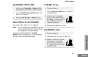
... and talk at a distance of about 1 to 2 inches (2.5 to 5 cm) from your radio on . 2 Use the Channel Selector knob to select the desired channel. 3 Hold the radio in a vertical position with its microphone 1 to 2 inches (2.5 to the desired volume level. 3 Release the Volume Set or Monitor ...hear a continuous tone. 2 Turn the On/Off/Volume Control knob to 5 cm) away from the microphone. Note: Due to listen. Ask your radio on . 2 Adjust the radio's volume (see page 5); Your radio offers either 4 or 16 channels. RECEIVING A CALL 1 Turn your mouth. 15 English GETTING STARTED ...
... and talk at a distance of about 1 to 2 inches (2.5 to 5 cm) from your radio on . 2 Use the Channel Selector knob to select the desired channel. 3 Hold the radio in a vertical position with its microphone 1 to 2 inches (2.5 to the desired volume level. 3 Release the Volume Set or Monitor ...hear a continuous tone. 2 Turn the On/Off/Volume Control knob to 5 cm) away from the microphone. Note: Due to listen. Ask your radio on . 2 Adjust the radio's volume (see page 5); Your radio offers either 4 or 16 channels. RECEIVING A CALL 1 Turn your mouth. 15 English GETTING STARTED ...

User Manual
Page 22
Note: Press the PTT button, if required for your mouth. then press and release the PTT button. 4 Hold the radio in a vertical position with the microphone 1 to 2 inches (2.5 to access the last number dialed; b Press the key (1 to 9) corresponding to the number you want to call, or press "0" if... you want to call : Enter the deaccess code using the keypad, press the / key once to 5 cm) away from your radio. Note: To...
Note: Press the PTT button, if required for your mouth. then press and release the PTT button. 4 Hold the radio in a vertical position with the microphone 1 to 2 inches (2.5 to access the last number dialed; b Press the key (1 to 9) corresponding to the number you want to call, or press "0" if... you want to call : Enter the deaccess code using the keypad, press the / key once to 5 cm) away from your radio. Note: To...
User Manual
Page 24
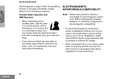
...facility where posted notices instruct you wear a portable two-way radio on board an aircraft. Any use of a radio must be using equipment that the antenna is at least 1 inch (2.5 centimeters) from your radio in accordance with its microphone 1 to 2 inches (2.5 to 5 centimeters) away from... MAN WITH RA your radio when on your body, ensure that is sensitive to external RF energy. • When instructed...
...facility where posted notices instruct you wear a portable two-way radio on board an aircraft. Any use of a radio must be using equipment that the antenna is at least 1 inch (2.5 centimeters) from your radio in accordance with its microphone 1 to 2 inches (2.5 to 5 centimeters) away from... MAN WITH RA your radio when on your body, ensure that is sensitive to external RF energy. • When instructed...

User Manual
Page 36
..., Single-Muff Over-the-Head, Medium-Weight Headset, Dual-Muff Behind-the-Head, Medium-Weight Headset, Dual-Muff Headset with Boom Microphone HNN9008_R HNN9009_R HNN9010_R HNN9011_R HNN9012_R HNN9013_R Small NiMH, High-Capacity Large NiMH, Ultra-High-Capacity Large NiMH, Ultra-High-Capacity FM Large NiCd...VHF 136-155 MHz 9 cm, Stubby VHF 155-174 MHz 9 cm, Stubby VHF 136-155 MHz 14 cm, Standard Length VHF 155-174 MHz 14 cm, Standard Length VHF 162-174MHz, Stubby VHF 150-161 MHz VHF 150-161 MHz, Stubby UHF 403-433 MHz UHF 433-470 MHz UHF 403-520 MHz, Whip UHF 470-510 MHz UHF 490-527 MHz UHF...
..., Single-Muff Over-the-Head, Medium-Weight Headset, Dual-Muff Behind-the-Head, Medium-Weight Headset, Dual-Muff Headset with Boom Microphone HNN9008_R HNN9009_R HNN9010_R HNN9011_R HNN9012_R HNN9013_R Small NiMH, High-Capacity Large NiMH, Ultra-High-Capacity Large NiMH, Ultra-High-Capacity FM Large NiCd...VHF 136-155 MHz 9 cm, Stubby VHF 155-174 MHz 9 cm, Stubby VHF 136-155 MHz 14 cm, Standard Length VHF 155-174 MHz 14 cm, Standard Length VHF 162-174MHz, Stubby VHF 150-161 MHz VHF 150-161 MHz, Stubby UHF 403-433 MHz UHF 433-470 MHz UHF 403-520 MHz, Whip UHF 470-510 MHz UHF 490-527 MHz UHF...

User Manual
Page 37
...64257;rst nine numbers in the table provided below. Release Scan button. Making a Phone Call (Keypad Radios Only) 1. HT750™ Quick Reference Card Record the functions for your radio's programmable buttons in your mouth. For further information, see pages 5 and 6 in vertical position with...on and set . Press PTT to listen. Sending a Call 1. Press PTT and speak clearly with microphone about 2.5 to 5 cm (1 to 2 inches) away from microphone. 3. Ending a Phone Call (Keypad Radios Only) 1. release it will be heard at the volume level you hear a tone. 2. Channel...
...64257;rst nine numbers in the table provided below. Release Scan button. Making a Phone Call (Keypad Radios Only) 1. HT750™ Quick Reference Card Record the functions for your radio's programmable buttons in your mouth. For further information, see pages 5 and 6 in vertical position with...on and set . Press PTT to listen. Sending a Call 1. Press PTT and speak clearly with microphone about 2.5 to 5 cm (1 to 2 inches) away from microphone. 3. Ending a Phone Call (Keypad Radios Only) 1. release it will be heard at the volume level you hear a tone. 2. Channel...

Service Manual
Page 4
...Microphone, and Universal Connector Flex Reassembly ....... 3-10 3.7.4 Keypad, Display, and Keypad/PassPort/Option Board Reassembly...... 3-10 3.7.5 Chassis Assembly Reassembly 3-11 3.7.6 Chassis and Front Cover Reassembly 3-11 3.7.7 DTMF Retrofit Kit Procedure (Optional Upgrade Procedure 3-12 3.7.8 Option Board Installation 3-13 3.8 HT750 Radio... Exploded Mechanical View and Parts List 3-15 3.8.1 HT750 Exploded View 3-15 3.8.2 HT750 Exploded View Parts List 3-16 3.8.3 HT1250 and HT1250•LS ...
...Microphone, and Universal Connector Flex Reassembly ....... 3-10 3.7.4 Keypad, Display, and Keypad/PassPort/Option Board Reassembly...... 3-10 3.7.5 Chassis Assembly Reassembly 3-11 3.7.6 Chassis and Front Cover Reassembly 3-11 3.7.7 DTMF Retrofit Kit Procedure (Optional Upgrade Procedure 3-12 3.7.8 Option Board Installation 3-13 3.8 HT750 Radio... Exploded Mechanical View and Parts List 3-15 3.8.1 HT750 Exploded View 3-15 3.8.2 HT750 Exploded View Parts List 3-16 3.8.3 HT1250 and HT1250•LS ...

Service Manual
Page 6
PassPort 6-3 6.4 Operation Display Codes 6-3 Chapter 7 Accessories 7-1 7.1 HT750/HT1250/HT1250•LS/HT1250•LS+/HT1550•XLS/MTX850/MTX950/ MTX850•LS/MTX8250/MTX9250/...Microphones 7-5 7.1.13 Manuals 7-5 7.1.14 Retrofit Front Cover Kits 7-5 Chapter 8 Model Chart and Test Specifications 8-1 8.1 UHF 403-470 MHz (Conventional 8-1 8.2 UHF 450-512 MHz (Conventional 8-2 8.3 UHF 403-470 MHz (LTR and PassPort 8-3 8.4 UHF 450-512 MHz (LTR and PassPort 8-4 8.5 UHF 403-470 MHz (Conventional/LTR 8-5 8.6 UHF 450-512 MHz (Conventional/LTR 8-6 8.7 VHF 136-174 MHz 8-7 8.8 VHF...
PassPort 6-3 6.4 Operation Display Codes 6-3 Chapter 7 Accessories 7-1 7.1 HT750/HT1250/HT1250•LS/HT1250•LS+/HT1550•XLS/MTX850/MTX950/ MTX850•LS/MTX8250/MTX9250/...Microphones 7-5 7.1.13 Manuals 7-5 7.1.14 Retrofit Front Cover Kits 7-5 Chapter 8 Model Chart and Test Specifications 8-1 8.1 UHF 403-470 MHz (Conventional 8-1 8.2 UHF 450-512 MHz (Conventional 8-2 8.3 UHF 403-470 MHz (LTR and PassPort 8-3 8.4 UHF 450-512 MHz (LTR and PassPort 8-4 8.5 UHF 403-470 MHz (Conventional/LTR 8-5 8.6 UHF 450-512 MHz (Conventional/LTR 8-6 8.7 VHF 136-174 MHz 8-7 8.8 VHF...
Service Manual
Page 9
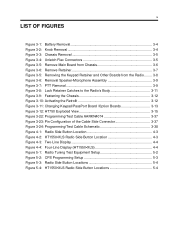
...Remove Retainer 3-7 Figure 3-5: Removing the Keypad Retainer and Other Boards from the Radio........ 3-8 Figure 3-6: Removal Speaker-Microphone Assembly 3-9 Figure 3-7: PTT Removal 3-9 Figure 3-8: Lock Retainer Catches to the Radio's Body 3-11 Figure 3-9: Fastening the Chassis 3-12 Figure 3-10: Activating ...the Retrofit 3-12 Figure 3-11: Changing Keypad/PassPort Board /Option Boards 3-13 Figure 3-12: HT750 ...
...Remove Retainer 3-7 Figure 3-5: Removing the Keypad Retainer and Other Boards from the Radio........ 3-8 Figure 3-6: Removal Speaker-Microphone Assembly 3-9 Figure 3-7: PTT Removal 3-9 Figure 3-8: Lock Retainer Catches to the Radio's Body 3-11 Figure 3-9: Fastening the Chassis 3-12 Figure 3-10: Activating ...the Retrofit 3-12 Figure 3-11: Changing Keypad/PassPort Board /Option Boards 3-13 Figure 3-12: HT750 ...

Service Manual
Page 23
... screws, it is customarily performed at the basic level, send this unit to a Motorola Authorized Service Center. (See Chapter, section 1.2.4 Technical Support on page 1-3 for disassembling the radio: l 3/16" flat blade screwdriver l Penknife-size screwdriver l TORX™ T6 ...3.6.2 Chassis Assembly/Disassembly on page 3-6 section 3.6.3 Keypad, Display, and Keypad/PassPort/Option Board Disassembly on page 3-6 section 3.6.4 Speaker, Microphone, and Universal Connector Flex Disassembly on page 3-8 section 3.6.5 PTT Disassembly on page 3-9 section 3.6.6 Control Top Disassembly on page 3-9 section...
... screws, it is customarily performed at the basic level, send this unit to a Motorola Authorized Service Center. (See Chapter, section 1.2.4 Technical Support on page 1-3 for disassembling the radio: l 3/16" flat blade screwdriver l Penknife-size screwdriver l TORX™ T6 ...3.6.2 Chassis Assembly/Disassembly on page 3-6 section 3.6.3 Keypad, Display, and Keypad/PassPort/Option Board Disassembly on page 3-6 section 3.6.4 Speaker, Microphone, and Universal Connector Flex Disassembly on page 3-8 section 3.6.5 PTT Disassembly on page 3-9 section 3.6.6 Control Top Disassembly on page 3-9 section...

Service Manual
Page 26
...u t i o n handling circuit boards. 2. Note the alignment of the chassis or the main board is required, lift the microphone flex circuit up, and carefully remove the microphone and its boot from the chassis (refer to the CMOS CAUTION in paragraph on page 3-2 before removing ! Remove the O-ring. ...5. If required in the chassis. If the disassembly of the radio chassis. 3.6.3 Keypad, Display, and Keypad/...
...u t i o n handling circuit boards. 2. Note the alignment of the chassis or the main board is required, lift the microphone flex circuit up, and carefully remove the microphone and its boot from the chassis (refer to the CMOS CAUTION in paragraph on page 3-2 before removing ! Remove the O-ring. ...5. If required in the chassis. If the disassembly of the radio chassis. 3.6.3 Keypad, Display, and Keypad/...

Service Manual
Page 27
... for the four remaining retainer arm tabs. Do not cut, bend, or pinch the heat seal. Pry the tab away from the front cover. C a u t i o n 7. b. Speaker-Microphone Flex Circuit Tail Flat Blade Screwdriver Keypad Retainer Arm Tabs (4) Retainer Top Hooks Retainer Figure 3-6: Remove Retainer 4. The display module is similar to the cover...
... for the four remaining retainer arm tabs. Do not cut, bend, or pinch the heat seal. Pry the tab away from the front cover. C a u t i o n 7. b. Speaker-Microphone Flex Circuit Tail Flat Blade Screwdriver Keypad Retainer Arm Tabs (4) Retainer Top Hooks Retainer Figure 3-6: Remove Retainer 4. The display module is similar to the cover...

Service Manual
Page 28
... Display Module Maintenance Keypad Option Board Keypad Radio Body Figure 3-5: Removing the Keypad Retainer and Other Boards from the Radio NOTE: At this assembly, you must peel-off the universal connector flex circuit escutcheon (label). 5. Pull the rubber microphone boot from the front cover, and remove... the universal connector tail of the radio until you slide it in the front cover. Then, remove the retainer by turning the screw...
... Display Module Maintenance Keypad Option Board Keypad Radio Body Figure 3-5: Removing the Keypad Retainer and Other Boards from the Radio NOTE: At this assembly, you must peel-off the universal connector flex circuit escutcheon (label). 5. Pull the rubber microphone boot from the front cover, and remove... the universal connector tail of the radio until you slide it in the front cover. Then, remove the retainer by turning the screw...

Service Manual
Page 29
...found inside the front cover (in the bottom of the boot. To remove the control top assembly, place a screwdriver next to replace the speaker or microphone, or both, do it against the control top escutcheon. Remove the PTT bezel by slightly bowing it away. 2. Grab the double-sided adhesive near... the volume potentiometer, then lift it until the top and bottom tabs are released from its boot, make sure the microphone port faces the round hole in between the four buttons on the PTT assembly). 2. The PTT seal can be disassembled using a small screwdriver as...
...found inside the front cover (in the bottom of the boot. To remove the control top assembly, place a screwdriver next to replace the speaker or microphone, or both, do it against the control top escutcheon. Remove the PTT bezel by slightly bowing it away. 2. Grab the double-sided adhesive near... the volume potentiometer, then lift it until the top and bottom tabs are released from its boot, make sure the microphone port faces the round hole in between the four buttons on the PTT assembly). 2. The PTT seal can be disassembled using a small screwdriver as...

Service Manual
Page 30
...against the front cover opening. Peel-off the liners from a new control top escutcheon and place it becomes fully engaged. 3.7.3 Speaker, Microphone, and Universal Connector Flex Reassembly 1. If display, keypad, or keypad option board are replacing the display, use a new double-sided ...microphone flex assembly through the opening . Reinsert the microphone and boot into the slots below the speaker. 6. Replace transmit light pipe and control top seal. 2. Press the PTT assembly against the adhesive. 3.7.2 PTT Reassembly 1. If necessary, press the T-tab toward the top of the radio...
...against the front cover opening. Peel-off the liners from a new control top escutcheon and place it becomes fully engaged. 3.7.3 Speaker, Microphone, and Universal Connector Flex Reassembly 1. If display, keypad, or keypad option board are replacing the display, use a new double-sided ...microphone flex assembly through the opening . Reinsert the microphone and boot into the slots below the speaker. 6. Replace transmit light pipe and control top seal. 2. Press the PTT assembly against the adhesive. 3.7.2 PTT Reassembly 1. If necessary, press the T-tab toward the top of the radio...

Service Manual
Page 36
...•XLS Parts List (Continued) Item Motorola Part Number 30 6062884K01 31 0304726J04 32 ... Module Pad, Retainer Front Retainer, Keypad Board Pad, Retainer Back Felt, Speaker Felt, Mic Boot, Mic Speaker Microphone Flex, Univ Conn Cap, 33pF Retainer, Speaker Boot, Backup Battery Table 3-8. 3-30 3.8.16 HT1550•XLS ...Exploded View Parts List Table 3-8. HT1550•XLS Parts List Item Motorola Part Number 1 See Section 7 in manual 44 HLN9714 Description Backup Battery Screw Contact, Finger (For UHF) Ctrl/RF Board Assembly Flex, Keypad/Controller Insulator, Antenna Pad,...
...•XLS Parts List (Continued) Item Motorola Part Number 30 6062884K01 31 0304726J04 32 ... Module Pad, Retainer Front Retainer, Keypad Board Pad, Retainer Back Felt, Speaker Felt, Mic Boot, Mic Speaker Microphone Flex, Univ Conn Cap, 33pF Retainer, Speaker Boot, Backup Battery Table 3-8. 3-30 3.8.16 HT1550•XLS ...Exploded View Parts List Table 3-8. HT1550•XLS Parts List Item Motorola Part Number 1 See Section 7 in manual 44 HLN9714 Description Backup Battery Screw Contact, Finger (For UHF) Ctrl/RF Board Assembly Flex, Keypad/Controller Insulator, Antenna Pad,...

Service Manual
Page 63
Compatible with a mobile antenna. (For HT Professional Series Conventional, LTR, and PassPort radios). Vehicular Adapter-VHF (136-174 MHz) provides tri-chemistry charging. Includes microphone and can be used with a mobile antenna. (For HT Professional Series Conventional and LTR radios). 1500 mAH NiMH High Capacity Battery (Standard With Unit) 1900 mAH NiMH Ultra High ...NA/LA manual) Wall Mount Kit for Accessory Connector Charger Insert Spacer - Compatible with BDN6706 or BDN6646) Dust Cover for Multi-unit Charger Vehicular Adapter-UHF (403-470 MHz) provides tri-chemistry charging.
Compatible with a mobile antenna. (For HT Professional Series Conventional, LTR, and PassPort radios). Vehicular Adapter-VHF (136-174 MHz) provides tri-chemistry charging. Includes microphone and can be used with a mobile antenna. (For HT Professional Series Conventional and LTR radios). 1500 mAH NiMH High Capacity Battery (Standard With Unit) 1900 mAH NiMH Ultra High ...NA/LA manual) Wall Mount Kit for Accessory Connector Charger Insert Spacer - Compatible with BDN6706 or BDN6646) Dust Cover for Multi-unit Charger Vehicular Adapter-UHF (403-470 MHz) provides tri-chemistry charging.
