Service Manual
Page 1
MVDP1085-FLRP 8 TFT DISPLAY PORTABLE DVD PLAYER CONTENTS Page SPECIFICATIONS ...2 BLOCK DIAGRAM...3 DISASSEMBLY INSTRUCTIONS ...4 SAFETY CHECKS...5 TROUBLESHOOTING ...6 PRINTED CIRCUIT BOARDS ...8 WIRING DIAGRAM ...12 EXPLODED VIEW ...14 MECHANICAL PARTS LIST ...15 ELECTRICAL PARTS LIST ...17 IC LEAD IDENTIFICATION AND INTERNAL DIAGRAM 27 SCHEMATIC DIAGRAM ...32
MVDP1085-FLRP 8 TFT DISPLAY PORTABLE DVD PLAYER CONTENTS Page SPECIFICATIONS ...2 BLOCK DIAGRAM...3 DISASSEMBLY INSTRUCTIONS ...4 SAFETY CHECKS...5 TROUBLESHOOTING ...6 PRINTED CIRCUIT BOARDS ...8 WIRING DIAGRAM ...12 EXPLODED VIEW ...14 MECHANICAL PARTS LIST ...15 ELECTRICAL PARTS LIST ...17 IC LEAD IDENTIFICATION AND INTERNAL DIAGRAM 27 SCHEMATIC DIAGRAM ...32
Service Manual
Page 2
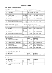
...set as 0 dB ref. Item Parameter 1 Output Level 2 S/N Ratio 3 Dynamic Range 4 Channel Separation (A-Weighted) 5 Distortion 6 Optical Digital Output Level 7 Frequency Response (20 Hz / 20 kHz) Test Disc: DVD=A-Bex TDV-500 Limits Conditions R ch L ch 1400 ±200 mV 1 kHz / 0 dB A-Weighted 70 dB 1 kHz / 0 dB W/WTD JIS A-Weighted --- Test Disc: TDV-500 Ref.=1500mV Item 1 2 3 4 5 10% Output Power S/N Ratio Parameter Channel... % 1 kHz / 0 dB W/WTD JIS --- Speaker Output : Load = 8 ohm; SPECIFICATIONS Audio Section : DC Power input = 12V Line Output : Load = 47 Kohm;
...set as 0 dB ref. Item Parameter 1 Output Level 2 S/N Ratio 3 Dynamic Range 4 Channel Separation (A-Weighted) 5 Distortion 6 Optical Digital Output Level 7 Frequency Response (20 Hz / 20 kHz) Test Disc: DVD=A-Bex TDV-500 Limits Conditions R ch L ch 1400 ±200 mV 1 kHz / 0 dB A-Weighted 70 dB 1 kHz / 0 dB W/WTD JIS A-Weighted --- Test Disc: TDV-500 Ref.=1500mV Item 1 2 3 4 5 10% Output Power S/N Ratio Parameter Channel... % 1 kHz / 0 dB W/WTD JIS --- Speaker Output : Load = 8 ohm; SPECIFICATIONS Audio Section : DC Power input = 12V Line Output : Load = 47 Kohm;
Service Manual
Page 4
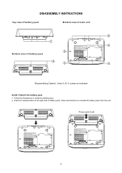
Press and hold 4 DISASSEMBLY INSTRUCTIONS Top view of battery pack Bottom view of main unit B C A B Bottom view of battery pack, follow the direction to install the battery pack. Press the release button at the right side of battery pack B B A Disassembling Cabinet : Undo A, B, C screws as indicated Install / Detach the battery pack Follow the illustrations to uninstall the battery pack from the unit.
Press and hold 4 DISASSEMBLY INSTRUCTIONS Top view of battery pack Bottom view of main unit B C A B Bottom view of battery pack, follow the direction to install the battery pack. Press the release button at the right side of battery pack B B A Disassembling Cabinet : Undo A, B, C screws as indicated Install / Detach the battery pack Follow the illustrations to uninstall the battery pack from the unit.
Service Manual
Page 5
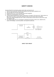
... after servicing this occurs, determine the cause of the leakage, correct the problem, and repeat the safety test. Set the meter to a high (150V AC) scale to ON or PLAY. 5. Any reading greater than 3 volts on all the externally connected test equipment and wires before testing the unit. 2. Use the safety test circuit as shown below. 3. Plug the power cord...
... after servicing this occurs, determine the cause of the leakage, correct the problem, and repeat the safety test. Set the meter to a high (150V AC) scale to ON or PLAY. 5. Any reading greater than 3 volts on all the externally connected test equipment and wires before testing the unit. 2. Use the safety test circuit as shown below. 3. Plug the power cord...
Service Manual
Page 6
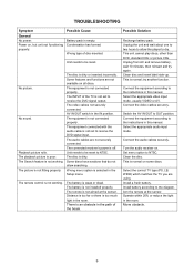
.... No sound. The video cables not securely connected. Unit needs to be reset. The remote control is poor. Possible Solution Recharge battery pack. Connect the video cables securely. The playback picture is not working . The picture is selected in the path of disc inserted. Wrong menu option is not fitting properly. This unit cannot play discs, other than DVD, standard CDs or picture CDs. Select the appropriate audio input mode. Clean the disc. Install a fresh battery. TROUBLESHOOTING Symptom General No power. The...
.... No sound. The video cables not securely connected. Unit needs to be reset. The remote control is poor. Possible Solution Recharge battery pack. Connect the video cables securely. The playback picture is not working . The picture is selected in the path of disc inserted. Wrong menu option is not fitting properly. This unit cannot play discs, other than DVD, standard CDs or picture CDs. Select the appropriate audio input mode. Clean the disc. Install a fresh battery. TROUBLESHOOTING Symptom General No power. The...
Service Manual
Page 7
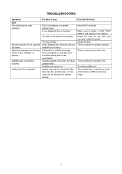
... being shown in the display. TROUBLESHOOTING Symptom DVD The unit does not start playback. Some functions do not operate as stated. Selected language is normal; Subtitles are not available on the disc (see disc jacket/case), or they may not be recorded on all discs. Possible Cause DVD not inserted, or inserted upside-down. If the audio or subtitle language does not appear on . "DVD VIDEO" will not be...
... being shown in the display. TROUBLESHOOTING Symptom DVD The unit does not start playback. Some functions do not operate as stated. Selected language is normal; Subtitles are not available on the disc (see disc jacket/case), or they may not be recorded on all discs. Possible Cause DVD not inserted, or inserted upside-down. If the audio or subtitle language does not appear on . "DVD VIDEO" will not be...
Service Manual
Page 12
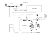
... LED BACK LIGHT PCB P/N: 0101-002602-02200 TFT Display LCD Panel KEY BOARD P/N : 010E-1721000-22 J9 12 P/N.: 1641-002040-10000 2 Pin #28 UL2651 L=40/3.5mm DC-JACK P/N.: 1641-115185-40000 15 Pin #30 UL1571 L=185mm Battery Rechargeable BATT1 BATTERY BOARD P/N: 010E-1721000-05 P/N: 1641-113275-40000 13Pin #30 UL1571 L=275 mm DVD Door Switch J10 SW2...
... LED BACK LIGHT PCB P/N: 0101-002602-02200 TFT Display LCD Panel KEY BOARD P/N : 010E-1721000-22 J9 12 P/N.: 1641-002040-10000 2 Pin #28 UL2651 L=40/3.5mm DC-JACK P/N.: 1641-115185-40000 15 Pin #30 UL1571 L=185mm Battery Rechargeable BATT1 BATTERY BOARD P/N: 010E-1721000-05 P/N: 1641-113275-40000 13Pin #30 UL1571 L=275 mm DVD Door Switch J10 SW2...
Service Manual
Page 14
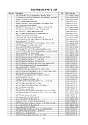
...H4.2 RoHS 1 084E-0070504-00 17 Screw 2 x 10 KH/ST ZN (White) RoHS 6 0431-020102-20002 18 PC Plate MEP1731 0.6T PC Sheet Black RoHS Pahs-Free 5 041E-0001731-02 19 Panel 8" TFT Front MEP1761-05 Moulded Glossy & Matte Pink RoHS 1 3061-001801-10000...Control Switch Bracket Pink RoHS 31 PCB MEP1731 Charge Board FR4 94V0 1.0 mm RoHS 1 082E-0021721-20 1 010E-1731102-05 32 Screw 2 x 6 BH/ST ZN (LF) 5 0431-020062-10002 33 Rubber For Rotating Shaft Sheet L (LF) 1 058E-0903830-00 34 PCB MEP1721 Panel Switch Board 94V0 FR4 1.0 mm RoHS 1 010E-1721000-03 35 MEP1731 Open Button...
...H4.2 RoHS 1 084E-0070504-00 17 Screw 2 x 10 KH/ST ZN (White) RoHS 6 0431-020102-20002 18 PC Plate MEP1731 0.6T PC Sheet Black RoHS Pahs-Free 5 041E-0001731-02 19 Panel 8" TFT Front MEP1761-05 Moulded Glossy & Matte Pink RoHS 1 3061-001801-10000...Control Switch Bracket Pink RoHS 31 PCB MEP1731 Charge Board FR4 94V0 1.0 mm RoHS 1 082E-0021721-20 1 010E-1731102-05 32 Screw 2 x 6 BH/ST ZN (LF) 5 0431-020062-10002 33 Rubber For Rotating Shaft Sheet L (LF) 1 058E-0903830-00 34 PCB MEP1721 Panel Switch Board 94V0 FR4 1.0 mm RoHS 1 010E-1721000-03 35 MEP1731 Open Button...

Service Manual
Page 15
...Button Bracket Pink RoHS MEP1761-05 OK Button RoHS MEP1731 Function Button (Square_4x) Electro Plating Silver RoHS Leaf Switch KFC-P01-09-RS RoHS MEP1731 DVD Door Opening Stopper Pink Gloss RoHS MEP1761 DVD Door Shaft Bracket Pink RoHS MEP1761-05 Main Unit Middle Cabinet w/o USB...Battery Sponge Sheet Black Fire Proof EVA With Nitto 500 Tape (LF) Battery Li-Polymer OSL-2S6535135P 7.4V 2500mAH RoHS MEP1731 Battery Spring 0.3 mm RoHS Adaptor (Battery Box Slide Switch) MEP1761 Moulded White RoHS PCB MEP1721 Battery Board 94V0 FR4 1.0 mm RoHS Bottom Cabinet Battery MEP1761 Moulded White... PARTS LIST -
...Button Bracket Pink RoHS MEP1761-05 OK Button RoHS MEP1731 Function Button (Square_4x) Electro Plating Silver RoHS Leaf Switch KFC-P01-09-RS RoHS MEP1731 DVD Door Opening Stopper Pink Gloss RoHS MEP1761 DVD Door Shaft Bracket Pink RoHS MEP1761-05 Main Unit Middle Cabinet w/o USB...Battery Sponge Sheet Black Fire Proof EVA With Nitto 500 Tape (LF) Battery Li-Polymer OSL-2S6535135P 7.4V 2500mAH RoHS MEP1731 Battery Spring 0.3 mm RoHS Adaptor (Battery Box Slide Switch) MEP1761 Moulded White RoHS PCB MEP1721 Battery Board 94V0 FR4 1.0 mm RoHS Bottom Cabinet Battery MEP1761 Moulded White... PARTS LIST -
Service Manual
Page 18
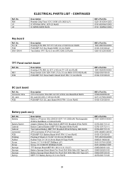
...;5% SOD-80 RoHS Diode BAT54S SMD (SOT-23) RoHS Diode LL4148 SMD SOD80 RoHS Diode LL4148 SMD SOD80 RoHS Leaf Switch KFC-P01-09-RS RoHS DVD Mechanism MG-9866H3H & HOP-1200X Pickup Head RoHS Electrolytic Capacitor 220 µF 16V 6.3 x 7 mm (LF) Electrolytic...LF) Fuse Time-Lag 32S-025H 2.5A 250V 3.6 x 10 UL/CSA/CCC/VDE RoHS Connector 2 Pin #28 UL1571 L=3/70/3 mm Red And Black RoHS Housing 2 Pin #28 UL2651 L=40/3.5 mm Pitch=2.0mm PH2.0 RoHS 24 Pin Connect FPC 0.5 mm SMT V.Type w/Lock (LF) FFC Cable 24 Pin...-135000-00011 0761-015021-00000 0761-013020-10000 19 ELECTRICAL PARTS LIST - CONTINUED Ref.
...;5% SOD-80 RoHS Diode BAT54S SMD (SOT-23) RoHS Diode LL4148 SMD SOD80 RoHS Diode LL4148 SMD SOD80 RoHS Leaf Switch KFC-P01-09-RS RoHS DVD Mechanism MG-9866H3H & HOP-1200X Pickup Head RoHS Electrolytic Capacitor 220 µF 16V 6.3 x 7 mm (LF) Electrolytic...LF) Fuse Time-Lag 32S-025H 2.5A 250V 3.6 x 10 UL/CSA/CCC/VDE RoHS Connector 2 Pin #28 UL1571 L=3/70/3 mm Red And Black RoHS Housing 2 Pin #28 UL2651 L=40/3.5 mm Pitch=2.0mm PH2.0 RoHS 24 Pin Connect FPC 0.5 mm SMT V.Type w/Lock (LF) FFC Cable 24 Pin...-135000-00011 0761-015021-00000 0761-013020-10000 19 ELECTRICAL PARTS LIST - CONTINUED Ref.

Service Manual
Page 19
... Q7,8 Q9 Q10,11 Q12 Q13,14 R1 R2,3 R4 R5 R6 R7 R8 R9 R10 R11 R12-14 R15 R16 R17 R18 R19 ELECTRICAL PARTS LIST - CONTINUED Description Inductor SMD 10 µH 1.2A 5 x 4 SCD0504T-100M-N RoHS Line Choke SMD 15 µH 1.8A ±20% SCD0705T-150M-N RoHS Ferrite Bead SMD ...10 µH ±10% 0805 Tape CMI201209X100KT (LF) Ferrite Bead SMD 0805 600 ohm/100 MHz RoHS Resistor Chip Fixed 0 ohm 1/16W ±5% 0603 (LF) Inductor 1.8 µH ±10% SMD 0805 CL201209T-1R8K-N RoHS Common Mode Choke 6 Pin SMD SBCB351620RID-221-B RoHS Inductor 1.8 µH ±10% SMD 0805 CL201209T-1R8K-N RoHS Common...
... Q7,8 Q9 Q10,11 Q12 Q13,14 R1 R2,3 R4 R5 R6 R7 R8 R9 R10 R11 R12-14 R15 R16 R17 R18 R19 ELECTRICAL PARTS LIST - CONTINUED Description Inductor SMD 10 µH 1.2A 5 x 4 SCD0504T-100M-N RoHS Line Choke SMD 15 µH 1.8A ±20% SCD0705T-150M-N RoHS Ferrite Bead SMD ...10 µH ±10% 0805 Tape CMI201209X100KT (LF) Ferrite Bead SMD 0805 600 ohm/100 MHz RoHS Resistor Chip Fixed 0 ohm 1/16W ±5% 0603 (LF) Inductor 1.8 µH ±10% SMD 0805 CL201209T-1R8K-N RoHS Common Mode Choke 6 Pin SMD SBCB351620RID-221-B RoHS Inductor 1.8 µH ±10% SMD 0805 CL201209T-1R8K-N RoHS Common...

Service Manual
Page 22
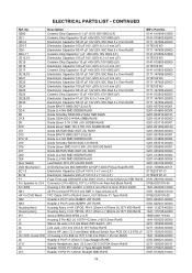
...ELECTRICAL PARTS LIST -...Fixed 75 ohm 1/16W ±5% 0603 (LF) Resistor Chip Fixed...Switch Slide 1P2T L=5 mm SK-12D02G5-RS RoHS Header 2 Pin P=2mm B2BPH JST RoHS Header 2 Pin P=1.25mm H. Type Straight SMD RoHS TFT-LCD Module PW080XU4 8" W/Led Backlight RoHS IC DC/DC Converter MP9141ES SOIC8 RoHS IC DC/DC Converter MP2259DJ SOIC8 RoHS IC MPEG MT1389DE/P-L WITH DivX LQFP256 RoHS IC Motor Driver...Audio Amplifier 2W ETK4863 TSSOP-20L RoHS IC D4558 SOP8 RoHS IC DC/DC Converter RT9284B-20PJ6E TSOT-23-6 RoHS Volume 16 RC1001GAXOA-HA1-A103 RoHS 27.000 MHz HC-49/S 30 pF ±20PPM 30 ohm (LF) Mfr's Part...
...ELECTRICAL PARTS LIST -...Fixed 75 ohm 1/16W ±5% 0603 (LF) Resistor Chip Fixed...Switch Slide 1P2T L=5 mm SK-12D02G5-RS RoHS Header 2 Pin P=2mm B2BPH JST RoHS Header 2 Pin P=1.25mm H. Type Straight SMD RoHS TFT-LCD Module PW080XU4 8" W/Led Backlight RoHS IC DC/DC Converter MP9141ES SOIC8 RoHS IC DC/DC Converter MP2259DJ SOIC8 RoHS IC MPEG MT1389DE/P-L WITH DivX LQFP256 RoHS IC Motor Driver...Audio Amplifier 2W ETK4863 TSSOP-20L RoHS IC D4558 SOP8 RoHS IC DC/DC Converter RT9284B-20PJ6E TSOT-23-6 RoHS Volume 16 RC1001GAXOA-HA1-A103 RoHS 27.000 MHz HC-49/S 30 pF ±20PPM 30 ohm (LF) Mfr's Part...
Service Manual
Page 23
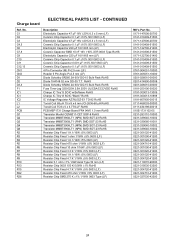
.... RoHS Diode Schottky SR260 2A 60V DO-15 Bulk Pack RoHS Fuse Time-Lag 32S-025H 2.5A 250V UL/CSA/CCC/VDE RoHS Charge IC Tiny13 SOIC w/Software RoHS Charge IC Tiny13 SOIC "Blank" RoHS IC Voltage Regulator AZ78L05Z-E1 TO-92...150 K 0.06W ±1% RoHS Resistor Chip Fixed 4.7 K 1/16W ±5% 0603 (LF) Resistor Chip Fixed 470 ohm 1/16W ±5% 0603 (LF) Resistor Chip SMD 270 K ±1% 1/16W 0603 Type (LF) Mfr's Part No. 0171-147606-20700 0141-010409-51500 ...Diode Schottky SR260 2A 60V DO-15 Bulk Pack RoHS Diode 1N4148 52 mm DO-35 T.T. Charge board ELECTRICAL PARTS LIST - CONTINUED Ref.
.... RoHS Diode Schottky SR260 2A 60V DO-15 Bulk Pack RoHS Fuse Time-Lag 32S-025H 2.5A 250V UL/CSA/CCC/VDE RoHS Charge IC Tiny13 SOIC w/Software RoHS Charge IC Tiny13 SOIC "Blank" RoHS IC Voltage Regulator AZ78L05Z-E1 TO-92...150 K 0.06W ±1% RoHS Resistor Chip Fixed 4.7 K 1/16W ±5% 0603 (LF) Resistor Chip Fixed 470 ohm 1/16W ±5% 0603 (LF) Resistor Chip SMD 270 K ±1% 1/16W 0603 Type (LF) Mfr's Part No. 0171-147606-20700 0141-010409-51500 ...Diode Schottky SR260 2A 60V DO-15 Bulk Pack RoHS Diode 1N4148 52 mm DO-35 T.T. Charge board ELECTRICAL PARTS LIST - CONTINUED Ref.
Service Manual
Page 24
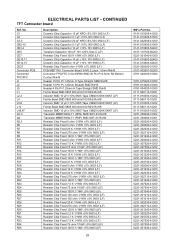
...P=0.5mm RA Bottom Contact RoHS Header 15 Pin P=1.25mm H.Type Straight SMD RoHS Header 13 Pin P=1.25mm Straight SMD RoHS Header 4 Pin P=1.25mm H.Type Straight SMD RoHS Ferrite Bead SMD 0805 600 ohm/100 MHz...Fixed 120 K 1/16W ±5% 0603 (LF) Resistor Chip Fixed 2.2 K 1/16W ±5% 0603 (LF) Resistor Chip Fixed 4.7 K 1/16W ±5% 0603 (LF) Resistor Chip Fixed 7.5 K 1/16W ±5% 0603 (LF) Resistor Chip Fixed 75 ohm 1/16W ±5% 0603 (LF) Resistor Chip Fixed 100 K 1/16W ±5% 0603 (LF) 25 Mfr's Part...41200 0221-301040-41200 ELECTRICAL PARTS LIST - CONTINUED TFT Connector board Ref.
...P=0.5mm RA Bottom Contact RoHS Header 15 Pin P=1.25mm H.Type Straight SMD RoHS Header 13 Pin P=1.25mm Straight SMD RoHS Header 4 Pin P=1.25mm H.Type Straight SMD RoHS Ferrite Bead SMD 0805 600 ohm/100 MHz...Fixed 120 K 1/16W ±5% 0603 (LF) Resistor Chip Fixed 2.2 K 1/16W ±5% 0603 (LF) Resistor Chip Fixed 4.7 K 1/16W ±5% 0603 (LF) Resistor Chip Fixed 7.5 K 1/16W ±5% 0603 (LF) Resistor Chip Fixed 75 ohm 1/16W ±5% 0603 (LF) Resistor Chip Fixed 100 K 1/16W ±5% 0603 (LF) 25 Mfr's Part...41200 0221-301040-41200 ELECTRICAL PARTS LIST - CONTINUED TFT Connector board Ref.
Service Manual
Page 25
... Sponge Sponge Sponge Spring Description Battery Li-Polymer OSL-2S6535135P 7.4V 2500mAH Rechargeable W/Wire Red/Black L=120mm RoHS Adaptor (Battery Box Slide Switch) MEP1761 Moulded White RoHS Bottom Cabinet Battery MEP1761 Moulded White RoHS Top Cabinet Battery MEP1761 Moulded White W/Spray ABS RoHS 4 Pin Connector (F) P=2.5 mm (LF) PCB MEP1721 Battery Board 94V0 FR4 1.0 mm RoHS Polybag 4 (Open) X 12-3/4 X 0.04 mm PE RoHS...
... Sponge Sponge Sponge Spring Description Battery Li-Polymer OSL-2S6535135P 7.4V 2500mAH Rechargeable W/Wire Red/Black L=120mm RoHS Adaptor (Battery Box Slide Switch) MEP1761 Moulded White RoHS Bottom Cabinet Battery MEP1761 Moulded White RoHS Top Cabinet Battery MEP1761 Moulded White W/Spray ABS RoHS 4 Pin Connector (F) P=2.5 mm (LF) PCB MEP1721 Battery Board 94V0 FR4 1.0 mm RoHS Polybag 4 (Open) X 12-3/4 X 0.04 mm PE RoHS...
Service Manual
Page 29
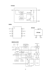
RT9166 VIN D4556 OUT 1 1 -IN 1 2 +IN 1 3 Vee 4 Current Limiting Sensor Thermal Shutdown Error Amp -+ 1.2V Reference VOUT GND 8 Vcc 7 OUT 2 6 - IN 2 5 + IN 2 RT9166 3 VIN RT9166 1 GND 2 VOUT 8MS29AL008D Vcc RY/BY# Vss RESET# WE# BYTE# State Control Command Register CE# OE# Sector Switches Erase Voltage Generator PGM Voltage Generator Chip Enable Output Enable Logic DQ0-DQ15 (A-1) Input / Output Buffers STB Data Latch Vcc Detector A0-A18 Timer Address Latch Y-Decoder STB X-Decoder Y-Gating Cell Matrix 30
RT9166 VIN D4556 OUT 1 1 -IN 1 2 +IN 1 3 Vee 4 Current Limiting Sensor Thermal Shutdown Error Amp -+ 1.2V Reference VOUT GND 8 Vcc 7 OUT 2 6 - IN 2 5 + IN 2 RT9166 3 VIN RT9166 1 GND 2 VOUT 8MS29AL008D Vcc RY/BY# Vss RESET# WE# BYTE# State Control Command Register CE# OE# Sector Switches Erase Voltage Generator PGM Voltage Generator Chip Enable Output Enable Logic DQ0-DQ15 (A-1) Input / Output Buffers STB Data Latch Vcc Detector A0-A18 Timer Address Latch Y-Decoder STB X-Decoder Y-Gating Cell Matrix 30

Service Manual
Page 30
... B Drivers PB0-PB5 Reset CLKI BD1937G Vin SW Q1 GND Thermaal Shutdown TSD S QD Current Sense Control 300kohm SHDNB PWMcomp Erramp FB - + - + + OSC 31 ATtiny13 VCC GND Instruction Register Instruction Decoder Control Lines Stack Pointer 8-Bit Databus Watchdog Oscillator Sram Program Counter Program Flash General Purpose Registers X Y Z ALU Watchdog Timer MCU Control Register MCU Status Register Timer/ Counter0 Interrupt Logic Programming Logic...
... B Drivers PB0-PB5 Reset CLKI BD1937G Vin SW Q1 GND Thermaal Shutdown TSD S QD Current Sense Control 300kohm SHDNB PWMcomp Erramp FB - + - + + OSC 31 ATtiny13 VCC GND Instruction Register Instruction Decoder Control Lines Stack Pointer 8-Bit Databus Watchdog Oscillator Sram Program Counter Program Flash General Purpose Registers X Y Z ALU Watchdog Timer MCU Control Register MCU Status Register Timer/ Counter0 Interrupt Logic Programming Logic...

Service Manual
Page 34
All capacitance values are indicated in "µF" (p=10-6 µF) 38 39 CONTINUED Notes : 1. All resistance values are indicated in "ohms" (K=1000 ohms, M=1000 Kohms). 2. Video & TFT out board SCHEMATIC DIAGRAMS -
All capacitance values are indicated in "µF" (p=10-6 µF) 38 39 CONTINUED Notes : 1. All resistance values are indicated in "ohms" (K=1000 ohms, M=1000 Kohms). 2. Video & TFT out board SCHEMATIC DIAGRAMS -

Service Manual
Page 35
Audio output board SCHEMATIC DIAGRAMS - All capacitance values are indicated in "µF" (p=10-6 µF) 40 41 CONTINUED Notes : 1. All resistance values are indicated in "ohms" (K=1000 ohms, M=1000 Kohms). 2.
Audio output board SCHEMATIC DIAGRAMS - All capacitance values are indicated in "µF" (p=10-6 µF) 40 41 CONTINUED Notes : 1. All resistance values are indicated in "ohms" (K=1000 ohms, M=1000 Kohms). 2.

Service Manual
Page 37
All resistance values are indicated in "ohms" (K=1000 ohms, M=1000 Kohms). 5. CONTINUED Panel connector board Notes : 1. SCHEMATIC DIAGRAMS - All capacitance values are indicated in "µF" (p=10-6 µF) 43
All resistance values are indicated in "ohms" (K=1000 ohms, M=1000 Kohms). 5. CONTINUED Panel connector board Notes : 1. SCHEMATIC DIAGRAMS - All capacitance values are indicated in "µF" (p=10-6 µF) 43


