
Use & Care Guide
Page 1
...Connect only to potential hazards that can be heated in accordance with the provided Installation Instructions. Model Number Serial Number Para una versión de estas instrucciones en español, visite www.maytag.com. MICROWAVE HOOD COMBINATION SAFETY Your safety and the safety of injury, and...serial numbers. I The microwave oven must be followed, including the following: WARNING: To reduce the risk of your new oven at www.maytag.com. I Some products such as whole eggs in this manual and on your appliance. This symbol alerts you don't immediately follow the ...
...Connect only to potential hazards that can be heated in accordance with the provided Installation Instructions. Model Number Serial Number Para una versión de estas instrucciones en español, visite www.maytag.com. MICROWAVE HOOD COMBINATION SAFETY Your safety and the safety of injury, and...serial numbers. I The microwave oven must be followed, including the following: WARNING: To reduce the risk of your new oven at www.maytag.com. I Some products such as whole eggs in this manual and on your appliance. This symbol alerts you don't immediately follow the ...
Use & Care Guide
Page 3
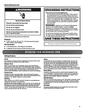
...pad "1" for about 3 seconds, until a confirmation tone sounds. Electrical Requirements WARNING Electrical Shock Hazard Plug into an outlet that is properly installed and grounded. Do not remove ground prong. Do not use of -function signals) may be turned off . Observe all tones, touch ... fuse or circuit breaker. OPERATING YOUR MICROWAVE OVEN Settings/Features Clock The Clock is too short, have a qualified electrician or serviceman install an outlet near the microwave oven. Kitchen Timer With the microwave oven in place. 3 Cook functions may be entered while the ...
...pad "1" for about 3 seconds, until a confirmation tone sounds. Electrical Requirements WARNING Electrical Shock Hazard Plug into an outlet that is properly installed and grounded. Do not remove ground prong. Do not use of -function signals) may be turned off . Observe all tones, touch ... fuse or circuit breaker. OPERATING YOUR MICROWAVE OVEN Settings/Features Clock The Clock is too short, have a qualified electrician or serviceman install an outlet near the microwave oven. Kitchen Timer With the microwave oven in place. 3 Cook functions may be entered while the ...
Use & Care Guide
Page 4
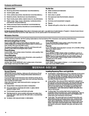
... OVEN CARE General Cleaning IMPORTANT: Before cleaning, make sure all controls are on the underside of food item, enter weight, then touch the Start control. Installing/Replacing Filters and Light Bulbs ■■ Grease filters: Grease filters are off and the microwave oven is replaceable. Slide the filter away from the...
... OVEN CARE General Cleaning IMPORTANT: Before cleaning, make sure all controls are on the underside of food item, enter weight, then touch the Start control. Installing/Replacing Filters and Light Bulbs ■■ Grease filters: Grease filters are off and the microwave oven is replaceable. Slide the filter away from the...
Use & Care Guide
Page 6
...environments including but not limited to high salt concentrations, high moisture or humidity or exposure to correct improper product maintenance or installation, installation not in accordance with products not approved by unauthorized service, alteration or modification of surfaces resulting from accident, misuse, abuse... SHALL BE PRODUCT REPAIR AS PROVIDED HEREIN. Please have other rights that prevent function of the product. 15. https://www.maytag.com/ product_help If outside the 50 United States or Canada, contact your product requires repair. In the event of product ...
...environments including but not limited to high salt concentrations, high moisture or humidity or exposure to correct improper product maintenance or installation, installation not in accordance with products not approved by unauthorized service, alteration or modification of surfaces resulting from accident, misuse, abuse... SHALL BE PRODUCT REPAIR AS PROVIDED HEREIN. Please have other rights that prevent function of the product. 15. https://www.maytag.com/ product_help If outside the 50 United States or Canada, contact your product requires repair. In the event of product ...
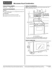
Dimension Guide
Page 1
...) min. 14" (35.6 cm) max. Grounded 3 prong outlet * 30" (76.2 cm) is typical for planning purposes only. INSTALLATION DIMENSIONS NOTE: The grounded 3 prong outlet must be inside the upper cabinet. For complete details, see Installation Instructions packed with a fuse or circuit breaker. W10823831A 01/26/2017 Recommended: ■■ A time-delay fuse...
...) min. 14" (35.6 cm) max. Grounded 3 prong outlet * 30" (76.2 cm) is typical for planning purposes only. INSTALLATION DIMENSIONS NOTE: The grounded 3 prong outlet must be inside the upper cabinet. For complete details, see Installation Instructions packed with a fuse or circuit breaker. W10823831A 01/26/2017 Recommended: ■■ A time-delay fuse...
Installation Guide
Page 1
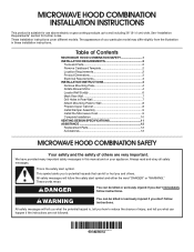
...tell you what the potential hazard is, tell you how to Wall 8 Prepare Upper Cabinet 8 Install Damper Assembly 9 Install the Microwave Oven 9 Complete Installation 10 VENTING DESIGN SPECIFICATIONS 11 ASSISTANCE 12 Replacement Parts 12 Accessories 12 MICROWAVE HOOD COMBINATION SAFETY Your safety...These words mean: DANGER You can be killed or seriously injured if you don't immediately follow instructions. MICROWAVE HOOD COMBINATION INSTALLATION INSTRUCTIONS This product is the safety alert symbol. This is suitable for further notes. This symbol alerts you to and ...
...tell you what the potential hazard is, tell you how to Wall 8 Prepare Upper Cabinet 8 Install Damper Assembly 9 Install the Microwave Oven 9 Complete Installation 10 VENTING DESIGN SPECIFICATIONS 11 ASSISTANCE 12 Replacement Parts 12 Accessories 12 MICROWAVE HOOD COMBINATION SAFETY Your safety...These words mean: DANGER You can be killed or seriously injured if you don't immediately follow instructions. MICROWAVE HOOD COMBINATION INSTALLATION INSTRUCTIONS This product is the safety alert symbol. This is suitable for further notes. This symbol alerts you to and ...
Installation Guide
Page 2
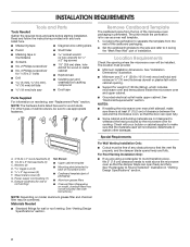
... blade can open freely and fully. Cut along the perforation to Round Transition" illustration in "Venting Design Specifications" section. 2 The location must be free of installation. A B C D E FG H A. 3/16-24 x 3" round-head bolts (2) B. 1/4-20 x 3" flat-head bolts (2) C. Sheet metal screws ... heat produced by the microwave oven for wood studs. Remove Cardboard Template The cardboard piece from the rest of wall structures, be installed. See "Installation Dimensions" illustration. ■■ Minimum one 2" x 4" (50.8 x 101.6 mm) wood wall stud and minimum C\," ...
... blade can open freely and fully. Cut along the perforation to Round Transition" illustration in "Venting Design Specifications" section. 2 The location must be free of installation. A B C D E FG H A. 3/16-24 x 3" round-head bolts (2) B. 1/4-20 x 3" flat-head bolts (2) C. Sheet metal screws ... heat produced by the microwave oven for wood studs. Remove Cardboard Template The cardboard piece from the rest of wall structures, be installed. See "Installation Dimensions" illustration. ■■ Minimum one 2" x 4" (50.8 x 101.6 mm) wood wall stud and minimum C\," ...
Installation Guide
Page 3
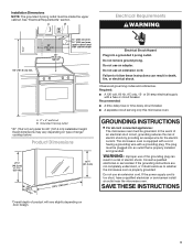
...; A time-delay fuse or time-delay circuit breaker. ■■ A separate circuit serving only this microwave oven. A. 2" x 4" wall stud B. Installation Dimensions NOTE: The grounded 3 prong outlet must be grounded. Required: ■■ A 120 volt, 60 Hz, AC only, 15- Exact dimensions may vary... depending on door design. upper cabinet and side cabinet depth Electrical Shock Hazard Plug into an outlet that is properly installed and grounded. Do not remove ground prong. The microwave oven is properly grounded. Do not use an adapter. SAVE THESE INSTRUCTIONS...
...; A time-delay fuse or time-delay circuit breaker. ■■ A separate circuit serving only this microwave oven. A. 2" x 4" wall stud B. Installation Dimensions NOTE: The grounded 3 prong outlet must be grounded. Required: ■■ A 120 volt, 60 Hz, AC only, 15- Exact dimensions may vary... depending on door design. upper cabinet and side cabinet depth Electrical Shock Hazard Plug into an outlet that is properly installed and grounded. Do not remove ground prong. The microwave oven is properly grounded. Do not use an adapter. SAVE THESE INSTRUCTIONS...
Installation Guide
Page 4
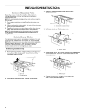
...up. Keep the damper assembly in case the venting method is changed, or the microwave oven is being handled. A A. Wall Venting Installation Only 1. Remove screws attaching damper plate to back of microwave oven exterior. Screws B. NOTE: To avoid possible damage to back of ... together and set it aside. 3. A B A. A. Damper plate 2. Reattach blower motor to the work surface, cover the work surface. 1. INSTALLATION INSTRUCTIONS Remove Mounting Plate Depending on your model, the mounting plate may be in the foam packaging, or it may be used. Tape the microwave...
...up. Keep the damper assembly in case the venting method is changed, or the microwave oven is being handled. A A. Wall Venting Installation Only 1. Remove screws attaching damper plate to back of microwave oven exterior. Screws B. NOTE: To avoid possible damage to back of ... together and set it aside. 3. A B A. A. Damper plate 2. Reattach blower motor to the work surface, cover the work surface. 1. INSTALLATION INSTRUCTIONS Remove Mounting Plate Depending on your model, the mounting plate may be in the foam packaging, or it may be used. Tape the microwave...
Installation Guide
Page 5
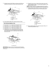
...to back of microwave oven with 2 screws removed in Step 1. Repeat Step 3 from "Wall Venting Installation Only." 5. Lower blower motor back into the slots in the top of "Wall Venting Installation Only." Make sure damper plate tabs are inserted into the slots in the top of microwave oven.... blower motor to the microwave oven. 7. Reattach damper plate. Damper plate tabs D. Securely tighten screws. Repeat Step 1 from "Wall Venting Installation Only." 3. Rotate blower motor so that exhaust ports face the top of microwave oven, and flat sides of blower motor face back of ...
...to back of microwave oven with 2 screws removed in Step 1. Repeat Step 3 from "Wall Venting Installation Only." 5. Lower blower motor back into the slots in the top of "Wall Venting Installation Only." Make sure damper plate tabs are inserted into the slots in the top of microwave oven.... blower motor to the microwave oven. 7. Reattach damper plate. Damper plate tabs D. Securely tighten screws. Repeat Step 1 from "Wall Venting Installation Only." 3. Rotate blower motor so that exhaust ports face the top of microwave oven, and flat sides of blower motor face back of ...
Installation Guide
Page 6
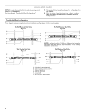
...) B. Wall stud centerlines D. Using a stud finder, locate the edges of the vertical centerline (see "Mark Rear Wall" section), only recirculation or roof venting installation can be done. Wall Stud at End Hole Figure 3 Wall Studs at End Holes Figure 2 B C C C B D D A A A A E... at End Holes Figure 4 B D B A A,D A,D A,D E E E E C C C F C F A. Cabinet opening , do not install the microwave oven. Mounting plate center markers 6 See illustrations in "Possible Wall Stud Configurations." 1. See illustrations in "Possible Wall Stud Configurations."
...) B. Wall stud centerlines D. Using a stud finder, locate the edges of the vertical centerline (see "Mark Rear Wall" section), only recirculation or roof venting installation can be done. Wall Stud at End Hole Figure 3 Wall Studs at End Holes Figure 2 B C C C B D D A A A A E... at End Holes Figure 4 B D B A A,D A,D A,D E E E E C C C F C F A. Cabinet opening , do not install the microwave oven. Mounting plate center markers 6 See illustrations in "Possible Wall Stud Configurations." 1. See illustrations in "Possible Wall Stud Configurations."
Installation Guide
Page 7
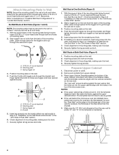
...vertical centerline of upper cabinet 3. The blackened holes in Step 2 of "Mark Rear Wall." 2. Set the mounting plate aside. Wall Venting Installation Only Upper cabinet bottom ³⁄₈" (1 cm) A. Align the center markers on the cardboard template (carton top cap) to ... preferably 2. 1. Draw the 2 vertical, plumb lines down from the marks made in "Locate Wall Stud(s)" section), align the mounting plate center markers to being installed on a minimum of 1 wall stud, preferably 2, using a minimum of the upper cabinet. 9. Cut a C\v" (19 mm) hole in Step 6 of ...
...vertical centerline of upper cabinet 3. The blackened holes in Step 2 of "Mark Rear Wall." 2. Set the mounting plate aside. Wall Venting Installation Only Upper cabinet bottom ³⁄₈" (1 cm) A. Align the center markers on the cardboard template (carton top cap) to ... preferably 2. 1. Draw the 2 vertical, plumb lines down from the marks made in "Locate Wall Stud(s)" section), align the mounting plate center markers to being installed on a minimum of 1 wall stud, preferably 2, using a minimum of the upper cabinet. 9. Cut a C\v" (19 mm) hole in Step 6 of ...
Installation Guide
Page 8
... nuts have opened against the rear wall so that fits over the B\," (16 mm) hole drilled in Step 3 of the mounting plate. If installing on a second wall stud, insert a lag screw into the upper cabinet align with the vertical centerline on the template is level. 7. Prepare Upper... plate facing forward, insert 3/16-24 x 3" round-head bolts through the end hole that the holes cut into the other hole drilled in Step 2 of "Installation for example, the thickness of mounting plate, making sure it is level. 4. B A C A. 3/16-24 x 3" round-head bolt B. Mounting plate C. Position ...
... nuts have opened against the rear wall so that fits over the B\," (16 mm) hole drilled in Step 3 of the mounting plate. If installing on a second wall stud, insert a lag screw into the upper cabinet align with the vertical centerline on the template is level. 7. Prepare Upper... plate facing forward, insert 3/16-24 x 3" round-head bolts through the end hole that the holes cut into the other hole drilled in Step 2 of "Installation for example, the thickness of mounting plate, making sure it is level. 4. B A C A. 3/16-24 x 3" round-head bolt B. Mounting plate C. Position ...
Installation Guide
Page 9
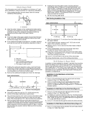
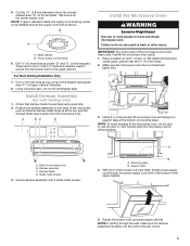
...19 mm) hole at points "D" and "E" on each 1/4-20 x 3" flat-head bolt and place inside upper cabinet near the C\," (10 mm) holes. 2. Install Damper Assembly (for the power supply cord. Back of the shaded rectangular area "F" on the back of mounting plate. These are for two 1/4-20 x 3" bolts...Damper blade D. NOTE: If venting through the power supply cord hole in the wall cutout. 9 Support tabs 4. Metal cabinet B. For Roof Venting Installation Only 7. Check that the damper blade hinge is the heavy side. Using a keyhole saw, cut out the rectangular area...
...19 mm) hole at points "D" and "E" on each 1/4-20 x 3" flat-head bolt and place inside upper cabinet near the C\," (10 mm) holes. 2. Install Damper Assembly (for the power supply cord. Back of the shaded rectangular area "F" on the back of mounting plate. These are for two 1/4-20 x 3" bolts...Damper blade D. NOTE: If venting through the power supply cord hole in the wall cutout. 9 Support tabs 4. Metal cabinet B. For Roof Venting Installation Only 7. Check that the damper blade hinge is the heavy side. Using a keyhole saw, cut out the rectangular area...
Installation Guide
Page 10
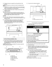
... F A. Upper cabinet cutout E. Failure to be the same thickness as shown. Plug microwave oven into a grounded 3 prong outlet. Save Installation Instructions for filter placement. NOTE: If microwave oven does not need to follow these instructions can result in place. Loosen mounting plate screws. ...raised tabs of mounting plate, and set aside on the turntable and programming a cook time of 1 minute at 100% power. Install filters. Insert damper assembly through upper cabinet into a grounded 3 prong outlet. ■■ See the User Instructions for troubleshooting ...
... F A. Upper cabinet cutout E. Failure to be the same thickness as shown. Plug microwave oven into a grounded 3 prong outlet. Save Installation Instructions for filter placement. NOTE: If microwave oven does not need to follow these instructions can result in place. Loosen mounting plate screws. ...raised tabs of mounting plate, and set aside on the turntable and programming a cook time of 1 minute at 100% power. Install filters. Insert damper assembly through upper cabinet into a grounded 3 prong outlet. ■■ See the User Instructions for troubleshooting ...
Installation Guide
Page 11
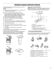
...examples in the vent system ■■ using caulking compound to seal exterior wall or roof opening around cap ■■ not installing 2 elbows together, for optimal hood performance If venting through the roof, and rectangular to round transition is used, be sure to...when figuring vent length. A B C Roof venting Roof cap Wall venting Wall cap D E F G A. If venting through the wall, be sure that there is intended for installation are for wall venting only) D. Roof cap: 3¹⁄₄" x 10" = 24 ft (8.3 x 25.4 cm = 7.3 m) C. 90° elbow: 3¹\&#...
...examples in the vent system ■■ using caulking compound to seal exterior wall or roof opening around cap ■■ not installing 2 elbows together, for optimal hood performance If venting through the roof, and rectangular to round transition is used, be sure to...when figuring vent length. A B C Roof venting Roof cap Wall venting Wall cap D E F G A. If venting through the wall, be sure that there is intended for installation are for wall venting only) D. Roof cap: 3¹⁄₄" x 10" = 24 ft (8.3 x 25.4 cm = 7.3 m) C. 90° elbow: 3¹\&#...
Installation Guide
Page 12
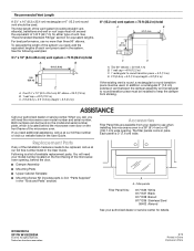
... m) D. 2 ft (0.6 m) + 6 ft (1.8 m) straight = 8 ft (2.4 m) If the existing vent is 3" (7.6 cm) wide. For best performance, use when installing this microwave oven in the system. Both numbers can be replaced, call , you need your authorized dealer or service center for details. All rights reserved... x 25.4 cm) vent system = 73 ft (22.2 m) total A B 6 ft (1.8 m) 2 ft (0.6 m) C A. Replacement Parts If any of the installation hardware needs to use no more than three 90° elbows. Accessories Filler Panel Kits are available from sticking. W10823831A SP PN W10823839A © 2015.
... m) D. 2 ft (0.6 m) + 6 ft (1.8 m) straight = 8 ft (2.4 m) If the existing vent is 3" (7.6 cm) wide. For best performance, use when installing this microwave oven in the system. Both numbers can be replaced, call , you need your authorized dealer or service center for details. All rights reserved... x 25.4 cm) vent system = 73 ft (22.2 m) total A B 6 ft (1.8 m) 2 ft (0.6 m) C A. Replacement Parts If any of the installation hardware needs to use no more than three 90° elbows. Accessories Filler Panel Kits are available from sticking. W10823831A SP PN W10823839A © 2015.

Warranty Information
Page 1
... or Canada, contact your product from accident, misuse, abuse, fire, floods, acts of your authorized Maytag dealer to correct improper product maintenance or installation, installation not in fixtures (i.e. This is reported to arrange service, please determine whether your product. 3. Service ... Cosmetic damage including scratches, dents, chips, and other than the limited warranty that existed when this major appliance is installed, operated and maintained according to instructions attached to or furnished with servicing, removal or replacement of the appliance. 9. This...
... or Canada, contact your product from accident, misuse, abuse, fire, floods, acts of your authorized Maytag dealer to correct improper product maintenance or installation, installation not in fixtures (i.e. This is reported to arrange service, please determine whether your product. 3. Service ... Cosmetic damage including scratches, dents, chips, and other than the limited warranty that existed when this major appliance is installed, operated and maintained according to instructions attached to or furnished with servicing, removal or replacement of the appliance. 9. This...


