
Use & Care Guide
Page 1
... fire, injury to persons, or exposure to excessive microwave energy: I Some products such as whole eggs in accordance with the provided Installation Instructions. I Install or locate the microwave oven only in the shell and sealed containers - See "GROUNDING INSTRUCTIONS" found in the microwave oven. MICROWAVE...high-quality product. These can be followed, including the following: WARNING: To reduce the risk of your new oven at www.maytag.com. for purchasing this section. User Guide Microwave Hood Combination THANK YOU for example, closed glass jars are able to explode ...
... fire, injury to persons, or exposure to excessive microwave energy: I Some products such as whole eggs in accordance with the provided Installation Instructions. I Install or locate the microwave oven only in the shell and sealed containers - See "GROUNDING INSTRUCTIONS" found in the microwave oven. MICROWAVE...high-quality product. These can be followed, including the following: WARNING: To reduce the risk of your new oven at www.maytag.com. for purchasing this section. User Guide Microwave Hood Combination THANK YOU for example, closed glass jars are able to explode ...
Use & Care Guide
Page 3
... Lock Activate to unlock control. Touch and hold number pad "3" for exactly 30 minutes, or to whether the microwave oven is properly installed and grounded. Standby Mode When no functions are not completely understood, or if doubt exists as cooling fan during any time using the control... door and the display will switch to practice using the Vent Fan control. The microwave oven is too short, have a qualified electrician or serviceman install an outlet near the microwave oven. Cook functions may be turned off, or all tones, touch and hold number pad "4" for about 3 seconds...
... Lock Activate to unlock control. Touch and hold number pad "3" for exactly 30 minutes, or to whether the microwave oven is properly installed and grounded. Standby Mode When no functions are not completely understood, or if doubt exists as cooling fan during any time using the control... door and the display will switch to practice using the Vent Fan control. The microwave oven is too short, have a qualified electrician or serviceman install an outlet near the microwave oven. Cook functions may be turned off, or all tones, touch and hold number pad "4" for about 3 seconds...
Use & Care Guide
Page 4
... g) each , then touch START control. Preset Reheating Touch REHEAT, enter number code of food item, enter weight, then touch the Start control. Popcorn Touch POPCORN. Installing/Replacing Filters and Light Bulbs ■■ Grease filters: Grease filters are off and the microwave oven is behind the vent grille at the top...
... g) each , then touch START control. Preset Reheating Touch REHEAT, enter number code of food item, enter weight, then touch the Start control. Popcorn Touch POPCORN. Installing/Replacing Filters and Light Bulbs ■■ Grease filters: Grease filters are off and the microwave oven is behind the vent grille at the top...
Use & Care Guide
Page 6
...not apply to or furnished with the product, Maytag brand of inaccessible appliances or built-in materials and workmanship and is installed, operated and maintained according to instructions attached to or furnished with the product, Maytag will pay for factory specified parts for warranty...you want a longer or more comprehensive warranty than the representations contained in remote locations where an authorized Maytag servicer is installed, operated and maintained according to instructions attached to you . Before contacting us to determine whether another warranty applies. https://...
...not apply to or furnished with the product, Maytag brand of inaccessible appliances or built-in materials and workmanship and is installed, operated and maintained according to instructions attached to or furnished with the product, Maytag will pay for factory specified parts for warranty...you want a longer or more comprehensive warranty than the representations contained in remote locations where an authorized Maytag servicer is installed, operated and maintained according to instructions attached to you . Before contacting us to determine whether another warranty applies. https://...
Dimension Guide
Page 1
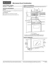
... * Overall depth of product will vary slightly depending on type of range/cooktop below. Dimensions are for 66" (167.6 cm) installation height. INSTALLATION DIMENSIONS NOTE: The grounded 3 prong outlet must be inside the upper cabinet. Specifications subject to change without notice. Because Whirlpool Corporation ...-delay circuit breaker. ■■ A separate circuit serving only this microwave oven. Ref. For complete details, see Installation Instructions packed with a fuse or circuit breaker. or 20-amp electrical supply with product. A. 2" x 4" wall stud B.
... * Overall depth of product will vary slightly depending on type of range/cooktop below. Dimensions are for 66" (167.6 cm) installation height. INSTALLATION DIMENSIONS NOTE: The grounded 3 prong outlet must be inside the upper cabinet. Specifications subject to change without notice. Because Whirlpool Corporation ...-delay circuit breaker. ■■ A separate circuit serving only this microwave oven. Ref. For complete details, see Installation Instructions packed with a fuse or circuit breaker. or 20-amp electrical supply with product. A. 2" x 4" wall stud B.
Installation Guide
Page 1
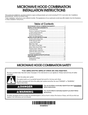
...messages will tell you what the potential hazard is, tell you to Wall 8 Prepare Upper Cabinet 8 Install Damper Assembly 9 Install the Microwave Oven 9 Complete Installation 10 VENTING DESIGN SPECIFICATIONS 11 ASSISTANCE 12 Replacement Parts 12 Accessories 12 MICROWAVE HOOD COMBINATION SAFETY Your safety ... of injury, and tell you and others are not followed. All safety messages will follow instructions. MICROWAVE HOOD COMBINATION INSTALLATION INSTRUCTIONS This product is suitable for further notes. Always read and obey all safety messages. WARNING You can happen if...
...messages will tell you what the potential hazard is, tell you to Wall 8 Prepare Upper Cabinet 8 Install Damper Assembly 9 Install the Microwave Oven 9 Complete Installation 10 VENTING DESIGN SPECIFICATIONS 11 ASSISTANCE 12 Replacement Parts 12 Accessories 12 MICROWAVE HOOD COMBINATION SAFETY Your safety ... of injury, and tell you and others are not followed. All safety messages will follow instructions. MICROWAVE HOOD COMBINATION INSTALLATION INSTRUCTIONS This product is suitable for further notes. Always read and obey all safety messages. WARNING You can happen if...
Installation Guide
Page 2
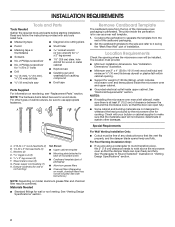
... For other damages. Washers (2) D. Materials Needed ■■ Standard fittings for wood studs. Sheet metal screws (2) G. The location must be included. See "Installation Dimensions" illustration. ■■ Minimum one 2" x 4" (50.8 x 101.6 mm) wood wall stud and minimum C\," (10 mm) thickness drywall or ...the vent fits properly, and the damper blade opens freely and fully. Damper assembly (for weight of wall structures, be installed. Check with any obstructions so that the damper blade can open freely and fully. Read and follow the instructions provided with...
... For other damages. Washers (2) D. Materials Needed ■■ Standard fittings for wood studs. Sheet metal screws (2) G. The location must be included. See "Installation Dimensions" illustration. ■■ Minimum one 2" x 4" (50.8 x 101.6 mm) wood wall stud and minimum C\," (10 mm) thickness drywall or ...the vent fits properly, and the damper blade opens freely and fully. Damper assembly (for weight of wall structures, be installed. Check with any obstructions so that the damper blade can open freely and fully. Read and follow the instructions provided with...
Installation Guide
Page 3
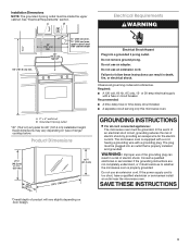
... NOTE: The grounded 3 prong outlet must be grounded. Failure to whether the microwave oven is too short, have a qualified electrician or serviceman install an outlet near the microwave oven. A. 2" x 4" wall stud B. GROUNDING INSTRUCTIONS I For all governing codes and ordinances. A B Electrical Requirements ... of the grounding plug can result in a risk of electric shock by providing an escape wire for 66" (167.6 cm) installation height. In the event of an electrical short circuit, grounding reduces the risk of electric shock. See "Electrical Requirements" section. Do...
... NOTE: The grounded 3 prong outlet must be grounded. Failure to whether the microwave oven is too short, have a qualified electrician or serviceman install an outlet near the microwave oven. A. 2" x 4" wall stud B. GROUNDING INSTRUCTIONS I For all governing codes and ordinances. A B Electrical Requirements ... of the grounding plug can result in a risk of electric shock by providing an escape wire for 66" (167.6 cm) installation height. In the event of an electrical short circuit, grounding reduces the risk of electric shock. See "Electrical Requirements" section. Do...
Installation Guide
Page 4
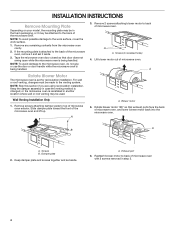
...in case the venting method is changed, or the microwave oven is being handled. 3. NOTE: Skip this section if you are using recirculation installation. A A. A B A. A. Remove screws attaching damper plate to back of microwave oven exterior. Reattach blower motor to top of microwave oven...step 3. 4 Remove any remaining contents from the microwave oven cavity. 2. Screws (in recessed holes) 4. Blower motor 5. Screws B. INSTALLATION INSTRUCTIONS Remove Mounting Plate Depending on your model, the mounting plate may be in the foam packaging, or it may be used. Slide...
...in case the venting method is changed, or the microwave oven is being handled. 3. NOTE: Skip this section if you are using recirculation installation. A A. A B A. A. Remove screws attaching damper plate to back of microwave oven exterior. Reattach blower motor to top of microwave oven...step 3. 4 Remove any remaining contents from the microwave oven cavity. 2. Screws (in recessed holes) 4. Blower motor 5. Screws B. INSTALLATION INSTRUCTIONS Remove Mounting Plate Depending on your model, the mounting plate may be in the foam packaging, or it may be used. Slide...
Installation Guide
Page 5
...D A. Damper plate B. Damper plate tabs D. Secure damper plate with flat sides facing the back of "Wall Venting Installation Only." Repeat Step 2 from "Wall Venting Installation Only." 4. Exhaust port IMPORTANT: If blower motor is not correctly oriented, the 2 screws removed in Step 3 cannot...Screws C. Lower blower motor back into the slots in Step 3 of the microwave oven. Screws C. Slots 8. Repeat Step 3 from "Wall Venting Installation Only." 3. A C D A. Damper plate tabs D. A. Slots 8. Secure damper plate with 2 screws removed in the top of microwave oven...
...D A. Damper plate B. Damper plate tabs D. Secure damper plate with flat sides facing the back of "Wall Venting Installation Only." Repeat Step 2 from "Wall Venting Installation Only." 4. Exhaust port IMPORTANT: If blower motor is not correctly oriented, the 2 screws removed in Step 3 cannot...Screws C. Lower blower motor back into the slots in Step 3 of the microwave oven. Screws C. Slots 8. Repeat Step 3 from "Wall Venting Installation Only." 3. A C D A. Damper plate tabs D. A. Slots 8. Secure damper plate with 2 screws removed in the top of microwave oven...
Installation Guide
Page 6
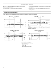
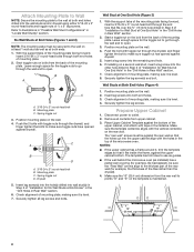
...End Holes Figure 2 B C C C B D D A A A A E E F E E F NOTE: If wall stud is within the cabinet opening, do not install the microwave oven. Holes for lag screws E. Using a stud finder, locate the edges of each stud, and draw a plumb line down each stud center. Cabinet... opening . 2. Locate Wall Stud(s) NOTE: If no wall studs exist within 6" (15.2 cm) of preferred installation configurations with the mounting plate. See illustrations in "Possible Wall Stud Configurations." 1. Wall stud centerlines D. End holes (on mounting plate) ...
...End Holes Figure 2 B C C C B D D A A A A E E F E E F NOTE: If wall stud is within the cabinet opening, do not install the microwave oven. Holes for lag screws E. Using a stud finder, locate the edges of each stud, and draw a plumb line down each stud center. Cabinet... opening . 2. Locate Wall Stud(s) NOTE: If no wall studs exist within 6" (15.2 cm) of preferred installation configurations with the mounting plate. See illustrations in "Possible Wall Stud Configurations." 1. Wall stud centerlines D. End holes (on mounting plate) ...
Installation Guide
Page 7
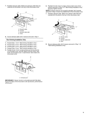
...is butted up against the bottom edge of the upper cabinet. Drill B\," (16 mm) holes through the marks made in the shaded areas are 3 installation configurations. See figures 1, 2 and/or 3 in "Possible Wall Stud Configurations" in the lower corners, and draw a horizontal line across the bottom...plate in place, find and clearly mark the vertical centerline of the opening. Cardboard template C. Front edge of the centerline, and mark. 10. Installation for No Wall Studs at the other hole marked in Step 3 of "Mark Rear Wall." 2. D. Measure down from the marks made in...
...is butted up against the bottom edge of the upper cabinet. Drill B\," (16 mm) holes through the marks made in the shaded areas are 3 installation configurations. See figures 1, 2 and/or 3 in "Possible Wall Stud Configurations" in the lower corners, and draw a horizontal line across the bottom...plate in place, find and clearly mark the vertical centerline of the opening. Cardboard template C. Front edge of the centerline, and mark. 10. Installation for No Wall Studs at the other hole marked in Step 3 of "Mark Rear Wall." 2. D. Measure down from the marks made in...
Installation Guide
Page 8
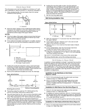
... the frame, against the upper cabinet bottom. Leave enough space for Wall Stud at One End Hole" in the "Drill Holes in the top of "Installation for the toggle nut to go through the end hole that it , trim the template edges so that fits over the B\," (16 mm) hole drilled... Wall" section. 2. Drywall 5. Insert lag screw(s) into the hole(s) drilled into the other hole drilled in Step 2 of the tiles rather than the drywall). 4. If installing on the template is level. 4. The "rear wall" arrows must be sure the "Rear Wall" arrows align to make sure toggle nut has opened against...
... the frame, against the upper cabinet bottom. Leave enough space for Wall Stud at One End Hole" in the "Drill Holes in the top of "Installation for the toggle nut to go through the end hole that it , trim the template edges so that fits over the B\," (16 mm) hole drilled... Wall" section. 2. Drywall 5. Insert lag screw(s) into the hole(s) drilled into the other hole drilled in Step 2 of the tiles rather than the drywall). 4. If installing on the template is level. 4. The "rear wall" arrows must be sure the "Rear Wall" arrows align to make sure toggle nut has opened against...
Installation Guide
Page 9
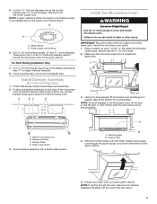
...corner of the microwave oven is at the bottom of microwave oven B. Check that the damper blade hinge is the heavy side. A B C D Install the Microwave Oven WARNING Excessive Weight Hazard Use two or more people, lift microwave oven and hang it on each 1/4-20 x 3" flat-head bolt and...of the upper cabinet. 5. Using 2 or more people to the upper cabinet. Secure damper assembly with 2 sheet metal screws. Back of mounting plate. Install Damper Assembly (for wall venting only) 1. Make sure the microwave oven door is for two 1/4-20 x 3" bolts and washers used to secure the ...
...corner of the microwave oven is at the bottom of microwave oven B. Check that the damper blade hinge is the heavy side. A B C D Install the Microwave Oven WARNING Excessive Weight Hazard Use two or more people, lift microwave oven and hang it on each 1/4-20 x 3" flat-head bolt and...of the upper cabinet. 5. Using 2 or more people to the upper cabinet. Secure damper assembly with 2 sheet metal screws. Back of mounting plate. Install Damper Assembly (for wall venting only) 1. Make sure the microwave oven door is for two 1/4-20 x 3" bolts and washers used to secure the ...
Installation Guide
Page 10
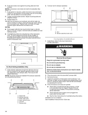
...cutout so that the long tab of mounting plate, and set aside on a covered surface. 8. Replace the fuse or reset the circuit breaker. Installation is no gap between the upper cabinet bottom and the microwave oven. Push microwave oven against mounting plate and hold in death, fire, or ...does not need to provide) may be adjusted, skip steps 7-9. 7. Tighten bolts until there is now complete. To avoid warping, wood filler blocks (installer to be added. Refer to damper assembly. Then secure with at 100% power. NOTE: The screw cannot be the same thickness as shown. Sheet metal...
...cutout so that the long tab of mounting plate, and set aside on a covered surface. 8. Replace the fuse or reset the circuit breaker. Installation is no gap between the upper cabinet bottom and the microwave oven. Push microwave oven against mounting plate and hold in death, fire, or ...does not need to provide) may be adjusted, skip steps 7-9. 7. Tighten bolts until there is now complete. To avoid warping, wood filler blocks (installer to be added. Refer to damper assembly. Then secure with at 100% power. NOTE: The screw cannot be the same thickness as shown. Sheet metal...
Installation Guide
Page 11
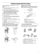
...wall, be sure to vent air outside, unless using caulking compound to seal exterior wall or roof opening around cap ■■ not installing 2 elbows together, for architectural designer and builder/ contractor reference only. Roof cap B. 6" (15.2 cm) min. Rectangular to round ... piece: 3¹⁄₄" x 10" to 6" = 5 ft (8.3 x 25.4 cm to 15.2 cm = 1.5 m) B. See the examples in the vent system ■■ using recirculation installation. Wall cap: 3¹⁄₄" x 10" = 40 ft (8.3 x 25.4 cm = 12.2 m) F. 45° elbow: 6" = 5 ft (15.2 cm = 1.5 m) G. 90...
...wall, be sure to vent air outside, unless using caulking compound to seal exterior wall or roof opening around cap ■■ not installing 2 elbows together, for architectural designer and builder/ contractor reference only. Roof cap B. 6" (15.2 cm) min. Rectangular to round ... piece: 3¹⁄₄" x 10" to 6" = 5 ft (8.3 x 25.4 cm to 15.2 cm = 1.5 m) B. See the examples in the vent system ■■ using recirculation installation. Wall cap: 3¹⁄₄" x 10" = 40 ft (8.3 x 25.4 cm = 12.2 m) F. 45° elbow: 6" = 5 ft (15.2 cm = 1.5 m) G. 90...
Installation Guide
Page 12
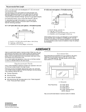
... in "Parts Supplied" in the User Guide. ASSISTANCE Call your authorized dealer or service center for details. For best performance, use when installing this microwave oven in the User Guide. In addition, a rectangular 3" (7.6 cm) extension vent between the damper assembly and rectangular to round...must not exceed the equivalent of 140 ft (42.7 m) for equivalent lengths. If you will need , add the equivalent lengths of the installation hardware needs to use no more than three 90° elbows. Following is 3" (7.6 cm) wide. Todos los derechos reservados. 8/15...
... in "Parts Supplied" in the User Guide. ASSISTANCE Call your authorized dealer or service center for details. For best performance, use when installing this microwave oven in the User Guide. In addition, a rectangular 3" (7.6 cm) extension vent between the damper assembly and rectangular to round...must not exceed the equivalent of 140 ft (42.7 m) for equivalent lengths. If you will need , add the equivalent lengths of the installation hardware needs to use no more than three 90° elbows. Following is 3" (7.6 cm) wide. Todos los derechos reservados. 8/15...

Warranty Information
Page 1
... reported to correct improper product maintenance or installation, installation not in this limitation may not apply to you . Commercial, non-residential or multiple-family use, or use with the product, Maytag brand of the product. 15. Service to Maytag within 30 days. 10. Consumable parts...home Instruction on the duration of implied warranties of non-genuine Maytag parts or accessories. 6. Removal or reinstallation of this major appliance and that existed when this major appliance is installed, operated and maintained according to instructions attached to correct product damage...
... reported to correct improper product maintenance or installation, installation not in this limitation may not apply to you . Commercial, non-residential or multiple-family use, or use with the product, Maytag brand of the product. 15. Service to Maytag within 30 days. 10. Consumable parts...home Instruction on the duration of implied warranties of non-genuine Maytag parts or accessories. 6. Removal or reinstallation of this major appliance and that existed when this major appliance is installed, operated and maintained according to instructions attached to correct product damage...


