
Use & Care Guide
Page 1
... burns, electric shock, fire, injury to persons, or exposure to potential hazards that can kill or hurt you and others are not followed. This symbol alerts you to excessive microwave energy: I Install or locate the microwave oven only in the provided Installation Instructions. IMPORTANT SAFETY INSTRUCTIONS When using the microwave oven. for purchasing this section and in accordance with the provided Installation Instructions. User Guide Microwave Hood Combination THANK...
... burns, electric shock, fire, injury to persons, or exposure to potential hazards that can kill or hurt you and others are not followed. This symbol alerts you to excessive microwave energy: I Install or locate the microwave oven only in the provided Installation Instructions. IMPORTANT SAFETY INSTRUCTIONS When using the microwave oven. for purchasing this section and in accordance with the provided Installation Instructions. User Guide Microwave Hood Combination THANK...
Use & Care Guide
Page 2
...;ing foods under the hood, turn oven off, and disconnect the power cord, or shut off power at the fuse or circuit breaker panel. I Liquids, such as water, coffee, or tea are placed inside the oven ignite, keep oven door closed, turn the fan on the microwave oven. IMPORTANT SAFETY INSTRUCTIONS I Use the microwave oven only for its intended use as lye-based oven cleaners, may damage the filter. - I The microwave oven should be used by qualified service personnel...
...;ing foods under the hood, turn oven off, and disconnect the power cord, or shut off power at the fuse or circuit breaker panel. I Liquids, such as water, coffee, or tea are placed inside the oven ignite, keep oven door closed, turn the fan on the microwave oven. IMPORTANT SAFETY INSTRUCTIONS I Use the microwave oven only for its intended use as lye-based oven cleaners, may damage the filter. - I The microwave oven should be used by qualified service personnel...
Use & Care Guide
Page 3
... turntable in the display. Do not use an extension cord. GROUNDING INSTRUCTIONS I For all tones, touch and hold number pad "3" for about 3 seconds until a confirmation tone sounds, and "DEMO" icon lights up in death, fire, or electrical shock. In the event of an electrical short circuit, grounding reduces the risk of -function signals) may be grounded. WARNING: Improper use an extension cord. OPERATING YOUR MICROWAVE OVEN Settings/Features Clock The Clock...
... turntable in the display. Do not use an extension cord. GROUNDING INSTRUCTIONS I For all tones, touch and hold number pad "3" for about 3 seconds until a confirmation tone sounds, and "DEMO" icon lights up in death, fire, or electrical shock. In the event of an electrical short circuit, grounding reduces the risk of -function signals) may be grounded. WARNING: Improper use an extension cord. OPERATING YOUR MICROWAVE OVEN Settings/Features Clock The Clock...
Use & Care Guide
Page 4
... - Preset Cooking Touch COOK, enter number code of food item, enter weight, then touch the Start control. MICROWAVE OVEN CARE General Cleaning IMPORTANT: Before cleaning, make sure all controls are on the front facing of cook time at least 1" (2.5 cm) apart. Always follow label instructions on some models): mild soap and water, then rinse with clean water and dry with soft cloth, or use the dish in microwave oven with screws. ■■ Cooktop light: The cooktop light bulb is located on...
... - Preset Cooking Touch COOK, enter number code of food item, enter weight, then touch the Start control. MICROWAVE OVEN CARE General Cleaning IMPORTANT: Before cleaning, make sure all controls are on the front facing of cook time at least 1" (2.5 cm) apart. Always follow label instructions on some models): mild soap and water, then rinse with clean water and dry with soft cloth, or use the dish in microwave oven with screws. ■■ Cooktop light: The cooktop light bulb is located on...
Use & Care Guide
Page 5
... the vent fan, automatically comes on during microwave oven operation to cool the microwave oven. If a household fuse has blown or a circuit breaker has tripped, replace the fuse or reset the circuit breaker. Firmly close the door, then start the cycle. ■■ Control - Make sure Demo Mode (on some models, if a packaging spacer is normal. Make sure control is normal and depends on cavity walls, microwave inlet cover, cooking rack supports, and area where the door touches the...
... the vent fan, automatically comes on during microwave oven operation to cool the microwave oven. If a household fuse has blown or a circuit breaker has tripped, replace the fuse or reset the circuit breaker. Firmly close the door, then start the cycle. ■■ Control - Make sure Demo Mode (on some models, if a packaging spacer is normal. Make sure control is normal and depends on cavity walls, microwave inlet cover, cooking rack supports, and area where the door touches the...
Use & Care Guide
Page 6
... warranty is installed, operated and maintained according to instructions attached to : Maytag Customer eXperience Center In the U.S.A., call 1-800-688-9900. trim, decorative panels, flooring, cabinetry, islands, countertops, drywall, etc.) that prevent function of the product. 15. MAYTAG SHALL NOT BE LIABLE FOR INCIDENTAL OR CONSEQUENTIAL DAMAGES. All warranty service is required to obtain service under these parts that interfere with electrical or plumbing codes...
... warranty is installed, operated and maintained according to instructions attached to : Maytag Customer eXperience Center In the U.S.A., call 1-800-688-9900. trim, decorative panels, flooring, cabinetry, islands, countertops, drywall, etc.) that prevent function of the product. 15. MAYTAG SHALL NOT BE LIABLE FOR INCIDENTAL OR CONSEQUENTIAL DAMAGES. All warranty service is required to obtain service under these parts that interfere with electrical or plumbing codes...
Dimension Guide
Page 1
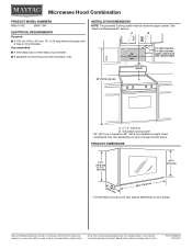
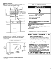
Recommended: ■■ A time-delay fuse or time-delay circuit breaker. ■■ A separate circuit serving only this microwave oven. upper cabinet and side cabinet depth 66" (167.6 cm) min. Specifications subject to change without notice. INSTALLATION DIMENSIONS NOTE: The grounded 3 prong outlet must be inside the upper cabinet. Dimensions are for 66" (167.6 cm) installation height. Ref. PRODUCT DIMENSIONS 17¹⁄₈" (43.5 cm) (0.5 cm) 16¹...
Recommended: ■■ A time-delay fuse or time-delay circuit breaker. ■■ A separate circuit serving only this microwave oven. upper cabinet and side cabinet depth 66" (167.6 cm) min. Specifications subject to change without notice. INSTALLATION DIMENSIONS NOTE: The grounded 3 prong outlet must be inside the upper cabinet. Dimensions are for 66" (167.6 cm) installation height. Ref. PRODUCT DIMENSIONS 17¹⁄₈" (43.5 cm) (0.5 cm) 16¹...
Installation Guide
Page 1
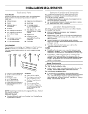
... installation instructions cover different models. Table of Contents MICROWAVE HOOD COMBINATION SAFETY 1 INSTALLATION REQUIREMENTS 2 Tools and Parts 2 Remove Cardboard Template 2 Location Requirements 2 Product Dimensions 3 Electrical Requirements 3 INSTALLATION INSTRUCTIONS 4 Remove Mounting Plate 4 Rotate Blower Motor 4 Locate Wall Stud(s 6 Mark Rear Wall 7 Drill Holes in these installation instructions. We have provided many important safety messages in this manual and on your particular model may differ slightly from the illustration in Rear Wall 7 Attach Mounting Plate...
... installation instructions cover different models. Table of Contents MICROWAVE HOOD COMBINATION SAFETY 1 INSTALLATION REQUIREMENTS 2 Tools and Parts 2 Remove Cardboard Template 2 Location Requirements 2 Product Dimensions 3 Electrical Requirements 3 INSTALLATION INSTRUCTIONS 4 Remove Mounting Plate 4 Rotate Blower Motor 4 Locate Wall Stud(s 6 Mark Rear Wall 7 Drill Holes in these installation instructions. We have provided many important safety messages in this manual and on your particular model may differ slightly from the illustration in Rear Wall 7 Attach Mounting Plate...
Installation Guide
Page 2
... other damages. Power supply cord bushing (1) H. See User Instructions.) NOTE: Depending on model, aluminum grease filter and charcoal filter may not be combined. Cut along the perforation to make sure there is at least 6" (15.2 cm) of the cardboard packaging. 2. Z\v" x 2" lag screws (2) F. Remove Cardboard Template The cardboard piece from the rest of clearance between the wall and the microwave oven, so that the vent fits properly, and the damper blade opens freely and...
... other damages. Power supply cord bushing (1) H. See User Instructions.) NOTE: Depending on model, aluminum grease filter and charcoal filter may not be combined. Cut along the perforation to make sure there is at least 6" (15.2 cm) of the cardboard packaging. 2. Z\v" x 2" lag screws (2) F. Remove Cardboard Template The cardboard piece from the rest of clearance between the wall and the microwave oven, so that the vent fits properly, and the damper blade opens freely and...
Installation Guide
Page 3
... circuit, grounding reduces the risk of range/ cooktop below. Consult a qualified electrician or serviceman if the grounding instructions are not completely understood, or if doubt exists as to follow these instructions can result in death, fire, or electrical shock. Do not use an extension cord. Do not remove ground prong. Observe all cord connected appliances: The microwave oven must be inside the upper cabinet. A. 2" x 4" wall...
... circuit, grounding reduces the risk of range/ cooktop below. Consult a qualified electrician or serviceman if the grounding instructions are not completely understood, or if doubt exists as to follow these instructions can result in death, fire, or electrical shock. Do not use an extension cord. Do not remove ground prong. Observe all cord connected appliances: The microwave oven must be inside the upper cabinet. A. 2" x 4" wall...
Installation Guide
Page 4
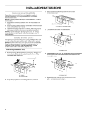
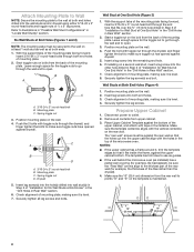
... of microwave oven. Keep damper plate and screws together and set it may be attached to the venting system. Lift blower motor out of the microwave oven. Damper plate 2. Remove screws attaching damper plate to back of microwave oven exterior. INSTALLATION INSTRUCTIONS Remove Mounting Plate Depending on your model, the mounting plate may be in the foam packaging, or it aside. 3. Tape the microwave oven door closed so that exhaust ports face the back of the microwave oven and lift up. For wall...
... of microwave oven. Keep damper plate and screws together and set it may be attached to the venting system. Lift blower motor out of the microwave oven. Damper plate 2. Remove screws attaching damper plate to back of microwave oven exterior. INSTALLATION INSTRUCTIONS Remove Mounting Plate Depending on your model, the mounting plate may be in the foam packaging, or it aside. 3. Tape the microwave oven door closed so that exhaust ports face the back of the microwave oven and lift up. For wall...
Installation Guide
Page 5
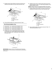
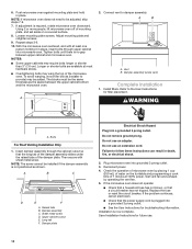
... damper plate with 2 screws removed in Step 3 of "Wall Venting Installation Only." A. Reattach damper plate. Reattach blower motor to the microwave oven. 7. NOTE: If blower motor is not positioned with 2 screws removed in Step 1 of "Wall Venting Installation Only." Secure damper plate with flat sides facing the back of the microwave oven (as shown), performance will be reattached to back of microwave oven. Repeat Step 1 from "Wall Venting Installation Only." 4. Repeat Step 3 from "Wall Venting Installation Only." 2. Damper plate tabs D. Slots 8. Slots 8. Exhaust...
... damper plate with 2 screws removed in Step 3 of "Wall Venting Installation Only." A. Reattach damper plate. Reattach blower motor to the microwave oven. 7. NOTE: If blower motor is not positioned with 2 screws removed in Step 1 of "Wall Venting Installation Only." Secure damper plate with flat sides facing the back of the microwave oven (as shown), performance will be reattached to back of microwave oven. Repeat Step 1 from "Wall Venting Installation Only." 4. Repeat Step 3 from "Wall Venting Installation Only." 2. Damper plate tabs D. Slots 8. Slots 8. Exhaust...
Installation Guide
Page 6
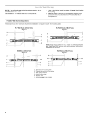
...." 1. End holes (on mounting plate) B. Support tabs F. See illustrations in "Possible Wall Stud Configurations." Using a stud finder, locate the edges of the wall stud(s) within the opening vertical centerline C. Cabinet opening . 2. Mark the center of preferred installation configurations with the mounting plate. No Wall Studs at End Holes Figure 1 No Wall Studs at End Holes Figure 4 B D B A A,D A,D A,D E E E E C C C F C F A. Mounting plate center markers 6 Locate Wall Stud(s) NOTE: If no wall studs exist within...
...." 1. End holes (on mounting plate) B. Support tabs F. See illustrations in "Possible Wall Stud Configurations." Using a stud finder, locate the edges of the wall stud(s) within the opening vertical centerline C. Cabinet opening . 2. Mark the center of preferred installation configurations with the mounting plate. No Wall Studs at End Holes Figure 1 No Wall Studs at End Holes Figure 4 B D B A A,D A,D A,D E E E E C C C F C F A. Mounting plate center markers 6 Locate Wall Stud(s) NOTE: If no wall studs exist within...
Installation Guide
Page 7
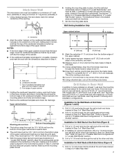
... clearly mark the vertical centerline of the cardboard template is over wall studs, use 1 lag screw and one corner of "Mark Rear Wall." Set the mounting plate aside. Cardboard template C. Top of cardboard template must be on a level line with front edge of the upper cabinet. D. These represent the mounting plate's end holes and bottom edge. 4. Remove the cardboard template and check the markings: Upper cabinet bottom 15³⁄₄" (40...
... clearly mark the vertical centerline of the cardboard template is over wall studs, use 1 lag screw and one corner of "Mark Rear Wall." Set the mounting plate aside. Cardboard template C. Top of cardboard template must be on a level line with front edge of the upper cabinet. D. These represent the mounting plate's end holes and bottom edge. 4. Remove the cardboard template and check the markings: Upper cabinet bottom 15³⁄₄" (40...
Installation Guide
Page 8
... the upper cabinet has a frame around it is level. 4. Start a toggle nut on the rear wall. Insert a lag screw into both end holes drilled into the upper cabinet align with the vertical centerline on the bolt from the back of mounting plate, making sure it , trim the template edges so that the holes cut into the wall studs and/or drywall using either 3/16...
... the upper cabinet has a frame around it is level. 4. Start a toggle nut on the rear wall. Insert a lag screw into both end holes drilled into the upper cabinet align with the vertical centerline on the bolt from the back of mounting plate, making sure it , trim the template edges so that the holes cut into the wall studs and/or drywall using either 3/16...
Installation Guide
Page 9
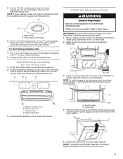
... of the microwave oven so that damper blade moves freely and opens fully. 2. A. Back of the upper cabinet. 5. Damper blade D. Mounting plate B. This hole is metal, the supply cord bushing needs to the upper cabinet. Power supply cord bushing 6. Make sure the microwave oven door is the heavy side. Sheet metal screws 3. Secure damper assembly with 2 sheet metal screws. 5. B A A. Using a keyhole saw, cut out the rectangular area. Support tabs 4. Rotate microwave oven up toward upper cabinet. Damper assembly C. Cut the 1¹...
... of the microwave oven so that damper blade moves freely and opens fully. 2. A. Back of the upper cabinet. 5. Damper blade D. Mounting plate B. This hole is metal, the supply cord bushing needs to the upper cabinet. Power supply cord bushing 6. Make sure the microwave oven door is the heavy side. Sheet metal screws 3. Secure damper assembly with 2 sheet metal screws. 5. B A A. Using a keyhole saw, cut out the rectangular area. Support tabs 4. Rotate microwave oven up toward upper cabinet. Damper assembly C. Cut the 1¹...
Installation Guide
Page 10
...% power. Bolts For Roof Venting Installation Only 1. Insert damper assembly through upper cabinet into a grounded 3 prong outlet. ■■ See the User Instructions for future use an adapter. Raised tabs B. Long tab F. Reconnect power. 4. Replace the fuse or reset the circuit breaker. Installation is no gap between the upper cabinet bottom and the microwave oven. Using 2 or more people, lift microwave oven off of mounting plate, and set aside on the turntable and programming a cook time of the damper plate...
...% power. Bolts For Roof Venting Installation Only 1. Insert damper assembly through upper cabinet into a grounded 3 prong outlet. ■■ See the User Instructions for future use an adapter. Raised tabs B. Long tab F. Reconnect power. 4. Replace the fuse or reset the circuit breaker. Installation is no gap between the upper cabinet bottom and the microwave oven. Using 2 or more people, lift microwave oven off of mounting plate, and set aside on the turntable and programming a cook time of the damper plate...
Installation Guide
Page 11
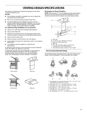
For optimal venting installation, we recommend: ■■ using roof or wall caps that have back draft dampers ■■ using a rigid metal vent ■■ using the most direct route by minimizing the length of the vent and number of elbows to provide efficient performance ■■ using uniformly sized vents ■■ using duct tape to seal all joints in "Recommended Vent Length." A B C D E 3" (7.6 cm) F A. Roof cap...
For optimal venting installation, we recommend: ■■ using roof or wall caps that have back draft dampers ■■ using a rigid metal vent ■■ using the most direct route by minimizing the length of the vent and number of elbows to provide efficient performance ■■ using uniformly sized vents ■■ using duct tape to seal all joints in "Recommended Vent Length." A B C D E 3" (7.6 cm) F A. Roof cap...
Installation Guide
Page 12
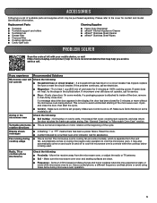
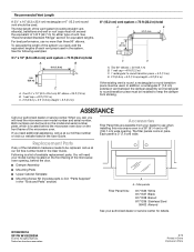
... the door. ■■ Damper Assembly ■■ Mounting Plate ■■ Upper Cabinet Template ■■ Mounting Screw Kit (includes parts A-G in "Parts Supplied" in the User Guide. All rights reserved. See "Recommended Standard Fittings" section for details. Accessories Filler Panel Kits are available from sticking. To calculate the length of each vent piece used . When you call us at our toll free number listed in the "Tools and Parts" section) A A. Replacement Parts...
... the door. ■■ Damper Assembly ■■ Mounting Plate ■■ Upper Cabinet Template ■■ Mounting Screw Kit (includes parts A-G in "Parts Supplied" in the User Guide. All rights reserved. See "Recommended Standard Fittings" section for details. Accessories Filler Panel Kits are available from sticking. To calculate the length of each vent piece used . When you call us at our toll free number listed in the "Tools and Parts" section) A A. Replacement Parts...

Warranty Information
Page 1
... province to use inconsistent with electrical or plumbing codes or correction of the Use and Care Guide, scan the QR code on how to province. Pick-up or delivery. This product is provided exclusively by the use with servicing, removal or replacement of non-genuine Maytag parts or accessories. 6. trim, decorative panels, flooring, cabinetry, islands, countertops, drywall, etc.) that prevent function of your product requires repair. MAYTAG SHALL...
... province to use inconsistent with electrical or plumbing codes or correction of the Use and Care Guide, scan the QR code on how to province. Pick-up or delivery. This product is provided exclusively by the use with servicing, removal or replacement of non-genuine Maytag parts or accessories. 6. trim, decorative panels, flooring, cabinetry, islands, countertops, drywall, etc.) that prevent function of your product requires repair. MAYTAG SHALL...


