
User Manual
Page 13
... 2 Quick Start ...3 Preparing Tools and Components 3 Installing a Processor 4 Installing DDR4 memory 5 Connecting the Front Panel Header 6 Installing the Motherboard 7 Installing SATA Drives 8 Installing a Graphics Card 9 Connecting Peripheral Devices 10 Connecting the Power Connectors 11 Power On...12 Specifications...15 Rear I/O Panel ...21 LAN Port LED Status Table 21 Audio Ports Configuration 21 Realtek HD Audio Manager 22 Overview of Components 24 Component Contents 25 CPU Socket ...26 DIMM Slots...27 PCI_E1~5: PCIe Expansion Slots 29 PCIe x16 slots bandwidth table...
... 2 Quick Start ...3 Preparing Tools and Components 3 Installing a Processor 4 Installing DDR4 memory 5 Connecting the Front Panel Header 6 Installing the Motherboard 7 Installing SATA Drives 8 Installing a Graphics Card 9 Connecting Peripheral Devices 10 Connecting the Power Connectors 11 Power On...12 Specifications...15 Rear I/O Panel ...21 LAN Port LED Status Table 21 Audio Ports Configuration 21 Realtek HD Audio Manager 22 Overview of Components 24 Component Contents 25 CPU Socket ...26 DIMM Slots...27 PCI_E1~5: PCIe Expansion Slots 29 PCIe x16 slots bandwidth table...

User Manual
Page 14
... Entering BIOS Setup 50 Resetting BIOS...51 Updating BIOS...51 EZ Mode ...52 Advanced Mode ...54 SETTINGS...55 Advanced...55 Boot...61 Security ...61 Save & Exit...62 OC...63 M-FLASH ...72 OC PROFILE ...73 HARDWARE MONITOR 74 Software Description 75 Installing Windows® 7/ 8.1/ 10 75 Installing Drivers 75 Installing Utilities 75 COMMAND CENTER 76 LIVE UPDATE 6...80 MYSTIC LIGHT...82 M-CLOUD ...83 RAMDISK...86 USB SPEED UP ...87 Intel® Extreme Tuning Utility 88 RAID Configuration 89 Using...
... Entering BIOS Setup 50 Resetting BIOS...51 Updating BIOS...51 EZ Mode ...52 Advanced Mode ...54 SETTINGS...55 Advanced...55 Boot...61 Security ...61 Save & Exit...62 OC...63 M-FLASH ...72 OC PROFILE ...73 HARDWARE MONITOR 74 Software Description 75 Installing Windows® 7/ 8.1/ 10 75 Installing Drivers 75 Installing Utilities 75 COMMAND CENTER 76 LIVE UPDATE 6...80 MYSTIC LIGHT...82 M-CLOUD ...83 RAMDISK...86 USB SPEED UP ...87 Intel® Extreme Tuning Utility 88 RAID Configuration 89 Using...

User Manual
Page 16
Storage Audio LAN Back Panel Connectors Continued from previous page Intel® X99 Chipset y 10x SATA 6Gb/s ports (2 ports from SATAe port) ƒ SATA1~6 support RAID 0, RAID 1, RAID 5 and RAID 10 ƒ SATA7~10 only support IDE mode and AHCI mode y 1x M.2 slot (Key M) ƒ For 40-lanes CPU, it supports up to PCIe 3.0 x4 and SATA 6Gb/s ƒ For 28-lanes CPU, it supports up to PCIe 2.0 x2 and SATA 6Gb/s ƒ Supports 2242/ 2260/ 2280/ 22110 storage devices y 1x U.2 port ƒ Supports PCIe 3.0 x4 NVMe storage y 1x...
Storage Audio LAN Back Panel Connectors Continued from previous page Intel® X99 Chipset y 10x SATA 6Gb/s ports (2 ports from SATAe port) ƒ SATA1~6 support RAID 0, RAID 1, RAID 5 and RAID 10 ƒ SATA7~10 only support IDE mode and AHCI mode y 1x M.2 slot (Key M) ƒ For 40-lanes CPU, it supports up to PCIe 3.0 x4 and SATA 6Gb/s ƒ For 28-lanes CPU, it supports up to PCIe 2.0 x2 and SATA 6Gb/s ƒ Supports 2242/ 2260/ 2280/ 22110 storage devices y 1x U.2 port ƒ Supports PCIe 3.0 x4 NVMe storage y 1x...
User Manual
Page 18
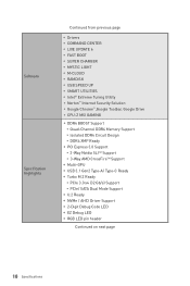
... Chrome™,Google Toolbar, Google Drive y CPU-Z MSI GAMING y DDR4 BOOST Support ƒ Quad-Channel DDR4 Memory Support ƒ Isolated DDR4 Circuit Design ƒ DDR4 XMP Ready y PCI Express 3.0 Support ƒ 3-Way Nvidia SLITM Support ƒ 3-Way AMD CrossFireTM Support y Multi-GPU y USB 3.1 Gen2 Type-A/ Type-C Ready y Turbo M.2 Ready ƒ PCIe 3.0 x4 (32 Gb/s) Support ƒ PCIe/ SATA Dual Mode Support y U.2 Ready y NVMe / AHCI Driver Support y 2-Digit Debug Code LED y EZ Debug LED y RGB LED pin header Continued on next page 18...
... Chrome™,Google Toolbar, Google Drive y CPU-Z MSI GAMING y DDR4 BOOST Support ƒ Quad-Channel DDR4 Memory Support ƒ Isolated DDR4 Circuit Design ƒ DDR4 XMP Ready y PCI Express 3.0 Support ƒ 3-Way Nvidia SLITM Support ƒ 3-Way AMD CrossFireTM Support y Multi-GPU y USB 3.1 Gen2 Type-A/ Type-C Ready y Turbo M.2 Ready ƒ PCIe 3.0 x4 (32 Gb/s) Support ƒ PCIe/ SATA Dual Mode Support y U.2 Ready y NVMe / AHCI Driver Support y 2-Digit Debug Code LED y EZ Debug LED y RGB LED pin header Continued on next page 18...

User Manual
Page 47
...- system setup, pre-OS user interface & selecting a bootable device (CD/DVD, HDD, USB, Network, Shell, ...) Debug Code LED Table SEC Progress Codes 01 Power on. Configuring memory 2F Memory initialization (other) 31 Memory Installed 32 CPU post-memory initialization is started LED Status Indicators 47 Cache initialization CPU post-memory initialization. 34 Application Processor(s) (AP) initialization 35 CPU post-memory initialization. System Management Mode (SMM) initialization 37 Post-Memory System Agent initialization is started 33 CPU post-memory initialization. Reset type...
...- system setup, pre-OS user interface & selecting a bootable device (CD/DVD, HDD, USB, Network, Shell, ...) Debug Code LED Table SEC Progress Codes 01 Power on. Configuring memory 2F Memory initialization (other) 31 Memory Installed 32 CPU post-memory initialization is started LED Status Indicators 47 Cache initialization CPU post-memory initialization. 34 Application Processor(s) (AP) initialization 35 CPU post-memory initialization. System Management Mode (SMM) initialization 37 Post-Memory System Agent initialization is started 33 CPU post-memory initialization. Reset type...
User Manual
Page 48
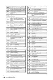
... Setup Verifying Password A9 Start of Setup AB Setup Input Wait AD Ready To Boot event AE Legacy Boot event AF Exit Boot Services event B0 Runtime Set Virtual Address MAP Begin B1 Runtime Set Virtual Address MAP End B2 Legacy Option ROM Initialization B3 System Reset B4 USB hot plug B5 PCI bus hot plug B6 Clean-up of NVRAM 48 LED Status Indicators SPD reading has failed Memory initialization error. Invalid 50 memory type or incompatible memory speed...
... Setup Verifying Password A9 Start of Setup AB Setup Input Wait AD Ready To Boot event AE Legacy Boot event AF Exit Boot Services event B0 Runtime Set Virtual Address MAP Begin B1 Runtime Set Virtual Address MAP End B2 Legacy Option ROM Initialization B3 System Reset B4 USB hot plug B5 PCI bus hot plug B6 Clean-up of NVRAM 48 LED Status Indicators SPD reading has failed Memory initialization error. Invalid 50 memory type or incompatible memory speed...
User Manual
Page 49
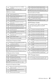
... waking up from the S3 sleep state 40 System is not found D8 Invalid password D9 Error loading Boot Option (LoadImage returned error) DA Boot Option is failed (StartImage returned error) DB Flash update is failed DC Reset protocol is not available S3 Resume Progress Codes E0 S3 Resume is stared (S3 Resume PPI is called by user (Forced recovery) F2 Recovery process started F3 F4 F5 - CPU Temperature 00 - 99 Displays...
... waking up from the S3 sleep state 40 System is not found D8 Invalid password D9 Error loading Boot Option (LoadImage returned error) DA Boot Option is failed (StartImage returned error) DB Flash update is failed DC Reset protocol is not available S3 Resume Progress Codes E0 S3 Resume is stared (S3 Resume PPI is called by user (Forced recovery) F2 Recovery process started F3 F4 F5 - CPU Temperature 00 - 99 Displays...
User Manual
Page 51
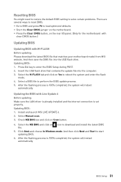
... automatically. Updating BIOS: 1. Install and launch MSI LIVE UPDATE 6. 2. BIOS Setup 51 Click Next and choose In Windows mode. Updating BIOS: 1. And then click Next and Start to reboot the system and enter the flash mode. 4. y Press the Clear CMOS button, on the motherboard. Insert the USB flash drive that matches your motherboard model from MSI website. Select the M-FLASH tab and click on Yes to start updating BIOS. 6. Resetting BIOS You might need to restore the default BIOS setting to solve certain problems. There...
... automatically. Updating BIOS: 1. Install and launch MSI LIVE UPDATE 6. 2. BIOS Setup 51 Click Next and choose In Windows mode. Updating BIOS: 1. And then click Next and Start to reboot the system and enter the flash mode. 4. y Press the Clear CMOS button, on the motherboard. Insert the USB flash drive that matches your motherboard model from MSI website. Select the M-FLASH tab and click on Yes to start updating BIOS. 6. Resetting BIOS You might need to restore the default BIOS setting to solve certain problems. There...
User Manual
Page 52
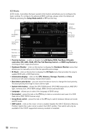
... disable the LAN Option ROM, Fast Boot, HD audio controller, IDE, AHCI, RAID, CPU Fan Fail Warning Control and BIOS Log Review by clicking on this button to display the M-Flash menu that allows you to select the X.M.P. click on their respective button. y M-Flash - y Boot device priority bar - shows the CPU/ DDR speed, CPU/ MB temperature, MB/ CPU type, memory size, CPU/ DDR voltage, BIOS version and build date. y XMP switch - click on this button to display the Hardware Monitor menu that provides the way to update BIOS with a USB flash drive. profile. you to configure...
... disable the LAN Option ROM, Fast Boot, HD audio controller, IDE, AHCI, RAID, CPU Fan Fail Warning Control and BIOS Log Review by clicking on this button to display the M-Flash menu that allows you to select the X.M.P. click on their respective button. y M-Flash - y Boot device priority bar - shows the CPU/ DDR speed, CPU/ MB temperature, MB/ CPU type, memory size, CPU/ DDR voltage, BIOS version and build date. y XMP switch - click on this button to display the Hardware Monitor menu that provides the way to update BIOS with a USB flash drive. profile. you to configure...

User Manual
Page 56
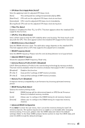
...Sets the operating channel of PCIe x16 slots for matching different installed devices. [Auto] This item will appear when Onboard LAN Controller is only available if the system supports 64-bit PCI decoding. fPower LED [Blinking] Sets shining behaviors of onboard power LED behaviors. f Integrated Peripherals Sets integrated peripherals' parameters, such as LAN, HDD, USB and audio. fLAN Option ROM [Disabled] Enables or disables the legacy network Boot Option ROM for optimizing IPv4 / IPv6 function. [Enabled] Enables UEFI network stack. [Disabled] Disables UEFI network stack. 56 BIOS Setup...
...Sets the operating channel of PCIe x16 slots for matching different installed devices. [Auto] This item will appear when Onboard LAN Controller is only available if the system supports 64-bit PCI decoding. fPower LED [Blinking] Sets shining behaviors of onboard power LED behaviors. f Integrated Peripherals Sets integrated peripherals' parameters, such as LAN, HDD, USB and audio. fLAN Option ROM [Disabled] Enables or disables the legacy network Boot Option ROM for optimizing IPv4 / IPv6 function. [Enabled] Enables UEFI network stack. [Disabled] Disables UEFI network stack. 56 BIOS Setup...
User Manual
Page 57
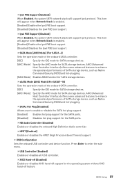
... for SATA storage devices. [AHCI Mode] Specify the AHCI mode for the SATA ports. fIpv4 PXE Support [Enabled] When Enabled, the system UEFI network stack will support Ipv6 protocol. This item will appear when Network Stack is enabled. [Enabled] Enables the Ipv4 PXE boot support. [Disabled] Disables the Ipv4 PXE boot support. fSATA Mode [AHCI Mode] (For SATA1~6) Sets the operation mode of SATA storage device, such as Native Command Queuing (NCQ) and hot-plugging. fHD Audio Controller [Enabled] Enables or disables the onboard High Definition Audio controller. f USB...
... for SATA storage devices. [AHCI Mode] Specify the AHCI mode for the SATA ports. fIpv4 PXE Support [Enabled] When Enabled, the system UEFI network stack will support Ipv6 protocol. This item will appear when Network Stack is enabled. [Enabled] Enables the Ipv4 PXE boot support. [Disabled] Disables the Ipv4 PXE boot support. fSATA Mode [AHCI Mode] (For SATA1~6) Sets the operation mode of SATA storage device, such as Native Command Queuing (NCQ) and hot-plugging. fHD Audio Controller [Enabled] Enables or disables the onboard High Definition Audio controller. f USB...

User Manual
Page 58
... Enter to the previous state (power on/ power off feature. fEHCI Hand-off [Enabled] Enables or disables EHCI hand-off support for other operating systems. Before enabling this item, make sure all installed devices & utilities (hardware & software) should meet the Windows 8.1/ 10 requirements. [Enabled] The system will be unavailable under legacy mode. [Disabled] The USB devices will switch to UEFI mode to meet the Windows equirement. [Disabled] Disables this function. f Power Management Setup Sets system Power Management of power, reset, PCH, audio LEDs...
... Enter to the previous state (power on/ power off feature. fEHCI Hand-off [Enabled] Enables or disables EHCI hand-off support for other operating systems. Before enabling this item, make sure all installed devices & utilities (hardware & software) should meet the Windows 8.1/ 10 requirements. [Enabled] The system will be unavailable under legacy mode. [Disabled] The USB devices will switch to UEFI mode to meet the Windows equirement. [Disabled] Disables this function. f Power Management Setup Sets system Power Management of power, reset, PCH, audio LEDs...
User Manual
Page 60
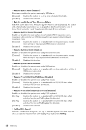
.... [Disabled] Disables this function. fResume By Onboard LAN [Disabled] Enables or disables the system wake up function of installed PCI-E expansion cards, integrated LAN controllers or USB devices which are supported by third party integrated chips. [Enabled] Enables the system to be awakened from the power saving modes when activity or input signal of PCIe device is detected. [Disabled] Disables this function. fHot Key [Ctrl+Space] Selects a combination of keys as a hot key to select the date & time settings). keys...
.... [Disabled] Disables this function. fResume By Onboard LAN [Disabled] Enables or disables the system wake up function of installed PCI-E expansion cards, integrated LAN controllers or USB devices which are supported by third party integrated chips. [Enabled] Enables the system to be awakened from the power saving modes when activity or input signal of PCIe device is detected. [Disabled] Disables this function. fHot Key [Ctrl+Space] Selects a combination of keys as a hot key to select the date & time settings). keys...

User Manual
Page 61
... change the BIOS items with administrator password. f GO2BIOS [Disabled] Allows system to enter BIOS setup directly by pressing the Power button for system security. After setting the user password, the state of this item will be configured automatically by long pressing the power button about 4 seconds when the system is enabled. [UEFI] Enables UEFI BIOS boot mode support only. [LEGACY+UEFI] Enables both Legacy BIOS boot mode and UEFI BIOS boot mode. User has limited rights to the BIOS setup by BIOS when Windows 8.1/ 10 WHQL Support is off. [Disabled] Disables...
... change the BIOS items with administrator password. f GO2BIOS [Disabled] Allows system to enter BIOS setup directly by pressing the Power button for system security. After setting the user password, the state of this item will be configured automatically by long pressing the power button about 4 seconds when the system is enabled. [UEFI] Enables UEFI BIOS boot mode support only. [LEGACY+UEFI] Enables both Legacy BIOS boot mode and UEFI BIOS boot mode. User has limited rights to the BIOS setup by BIOS when Windows 8.1/ 10 WHQL Support is off. [Disabled] Disables...
User Manual
Page 65
... memory modules. [Link] Allows user to configure the DRAM timing for all memory channel. f Extreme Memory Profile (X.M.P.) [Disabled] X.M.P. (Extreme Memory Profile) is installed. [Disabled] Disables this function. is the overclocking technology by choosing optimized memory preset. f DRAM Timing Mode [Auto] Selects the memory timing mode. [Auto] DRAM timings will be determined based on the installed CPU. If it occurs, please clear the CMOS data and restore the default settings. (Refer to the Clear CMOS jumper/ button section to clear the CMOS data, and enter the BIOS...
... memory modules. [Link] Allows user to configure the DRAM timing for all memory channel. f Extreme Memory Profile (X.M.P.) [Disabled] X.M.P. (Extreme Memory Profile) is installed. [Disabled] Disables this function. is the overclocking technology by choosing optimized memory preset. f DRAM Timing Mode [Auto] Selects the memory timing mode. [Auto] DRAM timings will be determined based on the installed CPU. If it occurs, please clear the CMOS data and restore the default settings. (Refer to the Clear CMOS jumper/ button section to clear the CMOS data, and enter the BIOS...
User Manual
Page 68
... voltages related to load the default settings for new devices. [Disabled] Disables this information menu at any time by pressing [F4]. The sub-menu shows the key features of installed memory. If set to Auto, BIOS will issue a warning message during boot and then needs to CPU. f MEMORY-Z Press Enter to enter the sub-menu. You can also access this function and keeps the current BIOS settings. Read only. f CPU Voltages control [Auto] These options allows you can set it manually. f DRAM Voltages control [Auto...
... voltages related to load the default settings for new devices. [Disabled] Disables this information menu at any time by pressing [F4]. The sub-menu shows the key features of installed memory. If set to Auto, BIOS will issue a warning message during boot and then needs to CPU. f MEMORY-Z Press Enter to enter the sub-menu. You can also access this function and keeps the current BIOS settings. Read only. f CPU Voltages control [Auto] These options allows you can set it manually. f DRAM Voltages control [Auto...

User Manual
Page 70
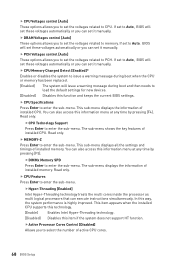
... lock bit. fLong Duration Maintained (s) [Auto] Sets the maintaining time for power-saving in halt state. [Disabled] Disables this function to select a CPU C-state level for power-saving when system is set to Simple. [Enabled] Enables the EIST to reduce the CPU frequency and voltage for CPU in Turbo Boost mode. This item appears when Intel C-State is a processor power management technology defined by ACPI. [Auto] This setting will be configured automatically by BIOS. [Enabled...
... lock bit. fLong Duration Maintained (s) [Auto] Sets the maintaining time for power-saving in halt state. [Disabled] Disables this function to select a CPU C-state level for power-saving when system is set to Simple. [Enabled] Enables the EIST to reduce the CPU frequency and voltage for CPU in Turbo Boost mode. This item appears when Intel C-State is a processor power management technology defined by ACPI. [Auto] This setting will be configured automatically by BIOS. [Enabled...

User Manual
Page 75
... POST (Power-On Self Test) to get into your computer in progress, after it has finished it will then be in your optical drive from CD or DVD... Press any key when screen shows Press any key to finish. 8. Start up your optical drive. 3. The software installation will prompt you to restart. 7. Click OK button to boot from the Boot Menu. 6. Software Description Installing Windows® 7/ 8.1/ 10 1. Installing Drivers 1. Click Install button...
... POST (Power-On Self Test) to get into your computer in progress, after it has finished it will then be in your optical drive from CD or DVD... Press any key when screen shows Press any key to finish. 8. Start up your optical drive. 3. The software installation will prompt you to restart. 7. Click OK button to boot from the Boot Menu. 6. Software Description Installing Windows® 7/ 8.1/ 10 1. Installing Drivers 1. Click Install button...

User Manual
Page 94
... network chipset driver has been installed. Lost BIOS password y Clear the CMOS, but no audio y Adjust the volume. There is connected to JFP1 pin header properly. y Connect the USB device to Keep DATA. y Some power supply units have a power button on . y Verify the Clear CMOS jumper JBAT1 is turned on the rear side, make sure the LAN port LEDs are properly illuminated. The computer does not boot after updating the BIOS y Clear the CMOS. The power is listed in Windows® Device Manager. y Remove secondary speakers/ headphones, HDMI cables, USB audio devices...
... network chipset driver has been installed. Lost BIOS password y Clear the CMOS, but no audio y Adjust the volume. There is connected to JFP1 pin header properly. y Connect the USB device to Keep DATA. y Some power supply units have a power button on . y Verify the Clear CMOS jumper JBAT1 is turned on the rear side, make sure the LAN port LEDs are properly illuminated. The computer does not boot after updating the BIOS y Clear the CMOS. The power is listed in Windows® Device Manager. y Remove secondary speakers/ headphones, HDMI cables, USB audio devices...
User Manual
Page 98
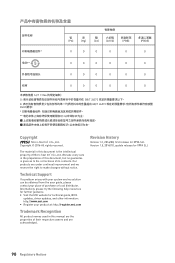
... resources for X99A SLI. Version 1.5, 2016/10, update release for technical guide, BIOS updates, driver updates, and other information: http://www.msi.com y Register your place of Micro-Star Int'l Co.,Ltd. The material in this document, but no solution can be obtained from the user guide, please contact your product at: http://register.msi.com Trademark Recognition All product names used in the...
... resources for X99A SLI. Version 1.5, 2016/10, update release for technical guide, BIOS updates, driver updates, and other information: http://www.msi.com y Register your place of Micro-Star Int'l Co.,Ltd. The material in this document, but no solution can be obtained from the user guide, please contact your product at: http://register.msi.com Trademark Recognition All product names used in the...


