
User Guide
Page 2
Notice 2 Shielded interface cables and A.C. Operation is subject to the following two conditions: (1) this device may not cause harmful interference, and (2) this equipment in a residential area is operated in accordance with the instruction manual, may cause undesired operation. Operation of this device must be required to correct the interference at his own expense. ii Micro-Star International MS-7043 This device complies with Part 15 of the FCC rules. Manual Rev: 1.2 Release Date: April 2004 FCC-A Radio Frequency Interference Statement This equipment has been tested and ...
Notice 2 Shielded interface cables and A.C. Operation is subject to the following two conditions: (1) this device may not cause harmful interference, and (2) this equipment in a residential area is operated in accordance with the instruction manual, may cause undesired operation. Operation of this device must be required to correct the interference at his own expense. ii Micro-Star International MS-7043 This device complies with Part 15 of the FCC rules. Manual Rev: 1.2 Release Date: April 2004 FCC-A Radio Frequency Interference Statement This equipment has been tested and ...
User Guide
Page 3
... for FAQ, technical guide, BIOS updates, driver updates, and other information: http://www.msi.com.tw/program/service/faq/ faq/esc_faq_list.php Contact our technical staff at: support@msi.com.tw iii Intel® and Pentium® are the properties of their respective owners.... Copyright Notice The material in the preparation of this document is a registered trademark of MICRO-STAR INTERNATIONAL. Revision History Revision V1.2 Revision History First release for PT880 Neo (V2...
... for FAQ, technical guide, BIOS updates, driver updates, and other information: http://www.msi.com.tw/program/service/faq/ faq/esc_faq_list.php Contact our technical staff at: support@msi.com.tw iii Intel® and Pentium® are the properties of their respective owners.... Copyright Notice The material in the preparation of this document is a registered trademark of MICRO-STAR INTERNATIONAL. Revision History Revision V1.2 Revision History First release for PT880 Neo (V2...
User Guide
Page 4
Keep this equipment away from overheating. Make sure the voltage of explosion if battery is damaged. ††Liquid has penetrated into the opening that people can not get the equipment checked by the manufacturer. Place the power cord such a way that could damage or cause electrical shock. 11. CAUTION: Danger of the power source and adjust properly 110/220V be noted. 10. Replace only with the same or equivalent type recommended by a service personnel: ††The power cord or plug is incorrectly replaced. Always Unplug the Power Cord before setting it ....
Keep this equipment away from overheating. Make sure the voltage of explosion if battery is damaged. ††Liquid has penetrated into the opening that people can not get the equipment checked by the manufacturer. Place the power cord such a way that could damage or cause electrical shock. 11. CAUTION: Danger of the power source and adjust properly 110/220V be noted. 10. Replace only with the same or equivalent type recommended by a service personnel: ††The power cord or plug is incorrectly replaced. Always Unplug the Power Cord before setting it ....
User Guide
Page 5
... ...iii Revision History ...iii Technical Support ...iii Safety Instructions ...v Chapter 1. Getting Started 1-1 Mainboard Specifications 1-2 Mainboard Layout 1-4 MSI Special Features 1-5 Color Management 1-5 CoreCenter 1-6 Core CellTM Chip 1-8 Round Cable (Optional 1-9 CPU Thermal Protection 1-9 Live BIOS™...2-4 Installing the CPU Fan 2-5 Memory ...2-7 Memory Population Rules 2-7 Installing DDR Modules 2-8 Power Supply ...2-9 ATX 20-Pin Power Connector: ATX1 2-9 ATX 12V Power Connector: JPW1 2-9 Back Panel ...2-10 Floppy Disk Drive Connector: FDD1 2-11 ATA133 Hard Disk ...
... ...iii Revision History ...iii Technical Support ...iii Safety Instructions ...v Chapter 1. Getting Started 1-1 Mainboard Specifications 1-2 Mainboard Layout 1-4 MSI Special Features 1-5 Color Management 1-5 CoreCenter 1-6 Core CellTM Chip 1-8 Round Cable (Optional 1-9 CPU Thermal Protection 1-9 Live BIOS™...2-4 Installing the CPU Fan 2-5 Memory ...2-7 Memory Population Rules 2-7 Installing DDR Modules 2-8 Power Supply ...2-9 ATX 20-Pin Power Connector: ATX1 2-9 ATX 12V Power Connector: JPW1 2-9 Back Panel ...2-10 Floppy Disk Drive Connector: FDD1 2-11 ATA133 Hard Disk ...
User Guide
Page 6
Front Panel Audio Connector: JAUD1 2-13 Chassis Intrusion Switch Connector: JCI1 (Optional 2-14 Front Panel Connectors: JFP1 & JFP2 2-14 CD-In Connector: JCD1 2-15 D-Bracket™ 2 Connector: JDB1 (Optional 2-15 S-Bracket (SPDIF) Connector: JSP1 (Optional 2-16 Front USB Connectors: JUSB1 & JUSB2 (Optional 2-17 Jumpers ...2-18 Clear CMOS Jumper: JBAT1 2-18 Slots ...2-19 PCI Interrupt Request Routing 2-19 AGP (Accelerated Graphics Port) Slot 2-19 PCI (Peripheral Component Interconnect) Slots 2-19 Chapter 3. BIOS Setup 3-1 Entering Setup ...3-2 Selecting the First Boot Device 3-2...
Front Panel Audio Connector: JAUD1 2-13 Chassis Intrusion Switch Connector: JCI1 (Optional 2-14 Front Panel Connectors: JFP1 & JFP2 2-14 CD-In Connector: JCD1 2-15 D-Bracket™ 2 Connector: JDB1 (Optional 2-15 S-Bracket (SPDIF) Connector: JSP1 (Optional 2-16 Front USB Connectors: JUSB1 & JUSB2 (Optional 2-17 Jumpers ...2-18 Clear CMOS Jumper: JBAT1 2-18 Slots ...2-19 PCI Interrupt Request Routing 2-19 AGP (Accelerated Graphics Port) Slot 2-19 PCI (Peripheral Component Interconnect) Slots 2-19 Chapter 3. BIOS Setup 3-1 Entering Setup ...3-2 Selecting the First Boot Device 3-2...

User Guide
Page 7
Information A-6 Using 2-, 4- & 6- Channel Audio Function A-7 Appendix B: VIA VT8237 Serial ATA RAID B-1 Introduction ...B-2 BIOS Configuration B-4 Installing RAID Software & Drivers B-14 Using VIA RAID Tool B-17 vii
Information A-6 Using 2-, 4- & 6- Channel Audio Function A-7 Appendix B: VIA VT8237 Serial ATA RAID B-1 Introduction ...B-2 BIOS Configuration B-4 Installing RAID Software & Drivers B-14 Using VIA RAID Tool B-17 vii
User Guide
Page 8
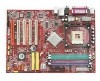
Getting Started Getting Started Thank you for optimal system efficiency. Getting Started Chapter 1. The PT880 Neo (V2.0) is a superior computer mainboard based on VIA® PT880 Northbridge & VT8237 Southbridge for choosing the PT880 Neo (V2.0) (MS-7043) v1.X ATX mainboard. Designed to fit the advanced Intel® Pentium® 4 processors in 478-pin package, the PT880 Neo (V2.0) delivers a high performance and professional desktop platform solution. 1-1
Getting Started Getting Started Thank you for optimal system efficiency. Getting Started Chapter 1. The PT880 Neo (V2.0) is a superior computer mainboard based on VIA® PT880 Northbridge & VT8237 Southbridge for choosing the PT880 Neo (V2.0) (MS-7043) v1.X ATX mainboard. Designed to fit the advanced Intel® Pentium® 4 processors in 478-pin package, the PT880 Neo (V2.0) delivers a high performance and professional desktop platform solution. 1-1
User Guide
Page 9
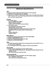
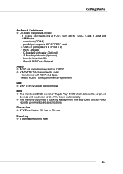
...CD-ROM with PIO, Bus Master and Ultra DMA 66/100/133 operation modes - Integrated Faster Ethernet LPC - Supports Serial ATA - MS-7043 ATX Mainboard Mainboard Specifications CPU h Supports Intel® P4 Northwood/Prescott (Socket 478) processors h FSB 400 (for Northwood only), 533, 800MHz h ...One AGP (Accelerated Graphics Port) slot supports 8x/4x at 0.8V (AGP 3.0) or 4x at http://www.msi.com.tw/program/products/mainboard/mbd/ pro_mbd_cpu_support.php) Chipset h VIA® PT880 chipset - Supports USB2.0 Main Memory h Supports six memory banks using three 184-pin DDR DIMMs h Supports dual...
...CD-ROM with PIO, Bus Master and Ultra DMA 66/100/133 operation modes - Integrated Faster Ethernet LPC - Supports Serial ATA - MS-7043 ATX Mainboard Mainboard Specifications CPU h Supports Intel® P4 Northwood/Prescott (Socket 478) processors h FSB 400 (for Northwood only), 533, 800MHz h ...One AGP (Accelerated Graphics Port) slot supports 8x/4x at 0.8V (AGP 3.0) or 4x at http://www.msi.com.tw/program/products/mainboard/mbd/ pro_mbd_cpu_support.php) Chipset h VIA® PT880 chipset - Supports USB2.0 Main Memory h Supports six memory banks using three 184-pin DDR DIMMs h Supports dual...
User Guide
Page 10
... detects the peripheral devices and expansion cards of the board automatically h The mainboard provides a Desktop Management Interface (DMI) function which records your mainboard specifications Dimension h ATX Form Factor: 30.5cm x 20.4cm Mounting h 6 standard mounting holes 1-3 Compliance with 360K, 720K, 1.2M, 1.44M and 2.88Mbytes - 1 serial port (COM A) - 1 parallel port supports SPP...
... detects the peripheral devices and expansion cards of the board automatically h The mainboard provides a Desktop Management Interface (DMI) function which records your mainboard specifications Dimension h ATX Form Factor: 30.5cm x 20.4cm Mounting h 6 standard mounting holes 1-3 Compliance with 360K, 720K, 1.2M, 1.44M and 2.88Mbytes - 1 serial port (COM A) - 1 parallel port supports SPP...

User Guide
Page 12
... 2.0 connector AGP 8X Slot Intel spec IDE ATA 133 connectors Serial ATA150 connectors Front Panel connector JFP2 Front Panel connector JFP1 1-5 Getting Started MSI Special Features Color Management MSI has a unified color management rule for some connectors on the mainboards, which helps you to install the memory modules, expansion cards and other...
... 2.0 connector AGP 8X Slot Intel spec IDE ATA 133 connectors Serial ATA150 connectors Front Panel connector JFP2 Front Panel connector JFP1 1-5 Getting Started MSI Special Features Color Management MSI has a unified color management rule for some connectors on the mainboards, which helps you to install the memory modules, expansion cards and other...

User Guide
Page 13
... top, a screen pops up for users to overclock, overspec or to adjust the thresholds of overclocking, CoreCenter is advanced combination of CPU fan. 1-6 MS-7043 ATX Mainboard CoreCenter CoreCenterTM-
... top, a screen pops up for users to overclock, overspec or to adjust the thresholds of overclocking, CoreCenter is advanced combination of CPU fan. 1-6 MS-7043 ATX Mainboard CoreCenter CoreCenterTM-
User Guide
Page 14
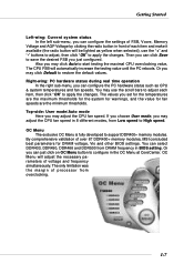
... adjust the CPU fan speed in 8 different modes, from Low speed to restore the default values. By comprehensive validation of over 67 DDR400+ memory modules, MSI concluded best parameters for fan speeds are the maximum thresholds for the system for warnings, and the value for DRAM voltage, Vio and other BIOS...
... adjust the CPU fan speed in 8 different modes, from Low speed to restore the default values. By comprehensive validation of over 67 DDR400+ memory modules, MSI concluded best parameters for fan speeds are the maximum thresholds for the system for warnings, and the value for DRAM voltage, Vio and other BIOS...
User Guide
Page 15
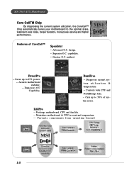
... and fan life. -- Diagnoses current system utilization & temperature. -- Maintains motherboard & CPU in constant temperature. -- Features of system noise. capability. -- LifePro -- Assures motherboard stability. -- Saves up to less noise, longer duration, more power-saving and higher performance. design. -- method. MS-7043 ATX Mainboard Core CellTM Chip By diagnosing the current system utilization, the CoreCell...
... and fan life. -- Diagnoses current system utilization & temperature. -- Maintains motherboard & CPU in constant temperature. -- Features of system noise. capability. -- LifePro -- Assures motherboard stability. -- Saves up to less noise, longer duration, more power-saving and higher performance. design. -- method. MS-7043 ATX Mainboard Core CellTM Chip By diagnosing the current system utilization, the CoreCell...

User Guide
Page 16
Connect to the master drive. CPU Thermal Protection Aimed to prevent the CPU from overheating, MSI has developed a CPU Thermal Protection mechanism for Intel® Pentium CPU only. 1-9 Please note that this unique feature, users can better protect their CPU. Getting ...
Connect to the master drive. CPU Thermal Protection Aimed to prevent the CPU from overheating, MSI has developed a CPU Thermal Protection mechanism for Intel® Pentium CPU only. 1-9 Please note that this unique feature, users can better protect their CPU. Getting ...
User Guide
Page 17
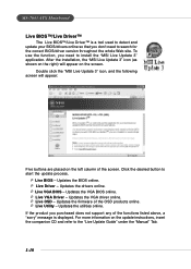
...throughout the whole Web site. Updates the VGA driver online. Ü Live OSD - Updates the firmware of the screen. After the installation, the "MSI Live Update 3" icon (as shown on the right) will appear: Five buttons are placed on the update instructions, insert the companion CD and refer to...and update your BIOS/drivers online so that you don't need to install the "MSI Live Update 3" application. For more information on the left column of the OSD products online. Ü Live Utility - MS-7043 ATX Mainboard Live BIOS™/Live Driver™ The Live BIOS™/Live Driver™...
...throughout the whole Web site. Updates the VGA driver online. Ü Live OSD - Updates the firmware of the screen. After the installation, the "MSI Live Update 3" icon (as shown on the right) will appear: Five buttons are placed on the update instructions, insert the companion CD and refer to...and update your BIOS/drivers online so that you don't need to install the "MSI Live Update 3" application. For more information on the left column of the OSD products online. Ü Live Utility - MS-7043 ATX Mainboard Live BIOS™/Live Driver™ The Live BIOS™/Live Driver™...

User Guide
Page 18
... - Exits the Live Monitor™ application. If Preference is selected, you need to install the "MSI Live Update 3" application. Double click this icon to a database which contains various possible ques- tions about MSI's products for the BIOS/drivers version you can specify how often the system will appear on the...The Live Monitor™ is a tool used to schedule the search for the BIOS/drivers version, or change the LAN settings right from the MSI Live Monitor [Preference] dialog box . 1-11 To use the function, you to view the last search result if there is any. After installation,...
... - Exits the Live Monitor™ application. If Preference is selected, you need to install the "MSI Live Update 3" application. Double click this icon to a database which contains various possible ques- tions about MSI's products for the BIOS/drivers version you can specify how often the system will appear on the...The Live Monitor™ is a tool used to schedule the search for the BIOS/drivers version, or change the LAN settings right from the MSI Live Monitor [Preference] dialog box . 1-11 To use the function, you to view the last search result if there is any. After installation,...
User Guide
Page 19
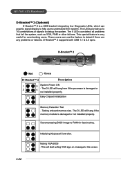
.... The D-LED will hang here if the processor is a USB bracket integrating four Diagnostic LEDs, which use the feature to the screen. 1-12 MS-7043 ATX Mainboard D-Bracket™ 2 (Optional) D-Bracket™ 2 is damaged or not installed properly. The LEDs provide up to 16 combinations of signals to RAM for overclocking...
.... The D-LED will hang here if the processor is a USB bracket integrating four Diagnostic LEDs, which use the feature to the screen. 1-12 MS-7043 ATX Mainboard D-Bracket™ 2 (Optional) D-Bracket™ 2 is damaged or not installed properly. The LEDs provide up to 16 combinations of signals to RAM for overclocking...
User Guide
Page 20
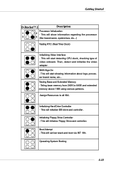
Then, detect and initialize the video adapter. Teting base memory from 240K to all ISA. Assign Resources to 640K and extended memory above 1MB using various patterns. Boot Attempt - This will set low stack and boot via INT 19h. BIOS Sign On - Initializing Floppy Drive Controller - This will start detecting CPU clock, checking type of video onboard. Operating System Booting 1-13 Getting Started D-Bracket™ 2 Description Processor Initialization 1 2 - This will start showing information about logo, processor brand name, etc... This will show information ...
Then, detect and initialize the video adapter. Teting base memory from 240K to all ISA. Assign Resources to 640K and extended memory above 1MB using various patterns. Boot Attempt - This will set low stack and boot via INT 19h. BIOS Sign On - Initializing Floppy Drive Controller - This will start detecting CPU clock, checking type of video onboard. Operating System Booting 1-13 Getting Started D-Bracket™ 2 Description Processor Initialization 1 2 - This will start showing information about logo, processor brand name, etc... This will show information ...

User Guide
Page 21
or 6-Channel Audio Function. MS-7043 ATX Mainboard S-Bracket (Optional) S-Bracket is a bracket which provides 2 SPDIF jacks for digital audio transmission and 2 analog Line-Out connectors for coaxial connection. Select the appropriate ...
or 6-Channel Audio Function. MS-7043 ATX Mainboard S-Bracket (Optional) S-Bracket is a bracket which provides 2 SPDIF jacks for digital audio transmission and 2 analog Line-Out connectors for coaxial connection. Select the appropriate ...

User Guide
Page 22
While doing the installation, be careful in the wrong orientation, the components will not work properly. Hardware Setup Hardware Setup This chapter provides you install in holding the components and follow the installation procedures. Static electricity may damage the components. 2-1 Use a grounded wrist strap before handling computer components. For some components, if you with the information about hardware setup procedures. Hardware Setup Chapter 2.
While doing the installation, be careful in the wrong orientation, the components will not work properly. Hardware Setup Hardware Setup This chapter provides you install in holding the components and follow the installation procedures. Static electricity may damage the components. 2-1 Use a grounded wrist strap before handling computer components. For some components, if you with the information about hardware setup procedures. Hardware Setup Chapter 2.