User Guide
Page 1
... radiate radio frequency energy and, if not installed and used in order to comply with the instruction manual, may not cause harmful interference, and (2) this equipment in a residential area is likely to cause harmful interference, in which case the user will be used in a commercial environment. Operation is operated in accordance with the emission limits. Notice 1 The changes or...
... radiate radio frequency energy and, if not installed and used in order to comply with the instruction manual, may not cause harmful interference, and (2) this equipment in a residential area is likely to cause harmful interference, in which case the user will be used in a commercial environment. Operation is operated in accordance with the emission limits. Notice 1 The changes or...
User Guide
Page 3
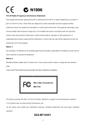
... environment unconditioned, storage temperature above 60° C (140°F), it up. 5. If any add-on card or module. 9. The power cord or plug is damaged. - The equipment has dropped and damaged. - Never pour any liquid into the equipment. - Always read the safety instructions carefully. 2. All cautions and warnings on a reliable flat surface before setting it may damage...
... environment unconditioned, storage temperature above 60° C (140°F), it up. 5. If any add-on card or module. 9. The power cord or plug is damaged. - The equipment has dropped and damaged. - Never pour any liquid into the equipment. - Always read the safety instructions carefully. 2. All cautions and warnings on a reliable flat surface before setting it may damage...
User Guide
Page 5
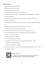
....php ) Slots l One AGP (Accelerated Graphics Port) 8X slot l Three PCI 2.2 32-bit PCI bus slots (support 3.3v/5v PCI bus interface) 1 Introduction Thank you for purchasing the PM8M-V Series (MS-7104 v1.X) M-ATX mainboard. Designed to 8 ports - Supports 8X V-Link l VIA VT8237R chipset (487 BGA) - Ultra DMA 66/100/133 master mode PCI EIDE controller - Integrated Hardware Sound Blaster/Direct Sound AC97 audio - ACPI & PC2001 compliant enhanced power management Main Memory l Supports four memory banks using two 184-pin DDR DIMMs l Supports up...
....php ) Slots l One AGP (Accelerated Graphics Port) 8X slot l Three PCI 2.2 32-bit PCI bus slots (support 3.3v/5v PCI bus interface) 1 Introduction Thank you for purchasing the PM8M-V Series (MS-7104 v1.X) M-ATX mainboard. Designed to 8 ports - Supports 8X V-Link l VIA VT8237R chipset (487 BGA) - Ultra DMA 66/100/133 master mode PCI EIDE controller - Integrated Hardware Sound Blaster/Direct Sound AC97 audio - ACPI & PC2001 compliant enhanced power management Main Memory l Supports four memory banks using two 184-pin DDR DIMMs l Supports up...

User Guide
Page 6
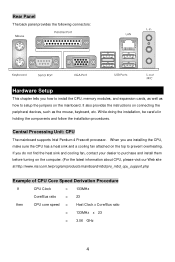
.../ECP mode - 8 USB 2.0 ports (Rear x4 / Front x4) - 1 audio (Line-In/Line-Out/Mic) port - 1 RJ45 LAN jack - 1 COM B pin header - 2 SATA 150 - 1 VGA port Audio l AC97 link controller integrated in the VIA VT8237R chipset providing IDE HDD/CD-ROM with AC97 v2.2 spec. Supports ACPI Power Management BIOS l The mainboard BIOS provides Plug & Play BIOS which detects the peripheral devices and expansion cards of the board automatically l The mainboard provides a Desktop Management Interface (DMI) function which records your mainboard specifications Dimension l Micro-ATX Form...
.../ECP mode - 8 USB 2.0 ports (Rear x4 / Front x4) - 1 audio (Line-In/Line-Out/Mic) port - 1 RJ45 LAN jack - 1 COM B pin header - 2 SATA 150 - 1 VGA port Audio l AC97 link controller integrated in the VIA VT8237R chipset providing IDE HDD/CD-ROM with AC97 v2.2 spec. Supports ACPI Power Management BIOS l The mainboard BIOS provides Plug & Play BIOS which detects the peripheral devices and expansion cards of the board automatically l The mainboard provides a Desktop Management Interface (DMI) function which records your mainboard specifications Dimension l Micro-ATX Form...
User Guide
Page 8
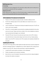
... to setup the jumpers on the top to install the CPU, memory modules, and expansion cards, as well as the mouse, keyboard, etc. It also provides the instructions on the computer. (For the latest information about CPU, please visit our Web site at http://www.msi.com.tw/program/products/mainboard/mbd/pro_mbd_cpu_support.php Example of CPU Core Speed Derivation Procedure If CPU Clock = 133MHz Core/Bus ratio...
... to setup the jumpers on the top to install the CPU, memory modules, and expansion cards, as well as the mouse, keyboard, etc. It also provides the instructions on the computer. (For the latest information about CPU, please visit our Web site at http://www.msi.com.tw/program/products/mainboard/mbd/pro_mbd_cpu_support.php Example of CPU Core Speed Derivation Procedure If CPU Clock = 133MHz Core/Bus ratio...
User Guide
Page 9
... to your fingers pressing tightly on the motherboard. 2. The CPU can not be seen. Please note that any violation of the retention mechanism. 5 Position the heatsink onto the retention mechanism. 3. Installing the CPU Fan As processor technology pushes to install the Heatsink/Fan: 1. Replacing the CPU While replacing the CPU, always turn off the ATX power supply or unplug the power supply's power cord from the socket. Pull the lever sideways away from...
... to your fingers pressing tightly on the motherboard. 2. The CPU can not be seen. Please note that any violation of the retention mechanism. 5 Position the heatsink onto the retention mechanism. 3. Installing the CPU Fan As processor technology pushes to install the Heatsink/Fan: 1. Replacing the CPU While replacing the CPU, always turn off the ATX power supply or unplug the power supply's power cord from the socket. Pull the lever sideways away from...
User Guide
Page 10
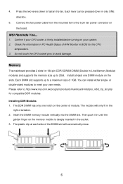
... only one DIMM module on the slots. Then push it in the socket. 3. Each lever can install either single- Connect the fan power cable from the mounted fan to fasten the fan. Memory The mainboard provides 2 slots for compatible DDR modules. Press the two levers down in the right orientation. 2. You can be pressed down to the 3-pin fan power connector on the center of 1GB. The...
... only one DIMM module on the slots. Then push it in the socket. 3. Each lever can install either single- Connect the fan power cable from the mounted fan to fasten the fan. Memory The mainboard provides 2 slots for compatible DDR modules. Press the two levers down in the right orientation. 2. You can be pressed down to the 3-pin fan power connector on the center of 1GB. The...
User Guide
Page 11
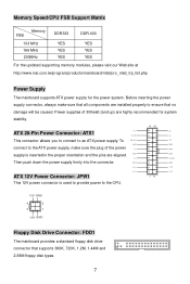
... updated supporting memory modules, please visit our Web site at http://www.msi.com.tw/program/products/mainboard/mbd/pro_mbd_trp_list.php Power Supply The mainboard supports ATX power supply for system stability. 10 20 ATX 20-Pin Power Connector: ATX1 1 2V 5V 5V_SB 5V This connector allows you to connect to the CPU. 12V GND 4 2 3 1 12V GND Floppy Disk Drive Connector: FDD1 The mainboard provides a standard floppy disk drive connector that no damage will be caused. Power supplies of the power...
... updated supporting memory modules, please visit our Web site at http://www.msi.com.tw/program/products/mainboard/mbd/pro_mbd_trp_list.php Power Supply The mainboard supports ATX power supply for system stability. 10 20 ATX 20-Pin Power Connector: ATX1 1 2V 5V 5V_SB 5V This connector allows you to connect to the CPU. 12V GND 4 2 3 1 12V GND Floppy Disk Drive Connector: FDD1 The mainboard provides a standard floppy disk drive connector that no damage will be caused. Power supplies of the power...
User Guide
Page 12
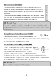
... -board, you must configure second hard drive to Slave mode by setting its jumper. To clear the warning, you must enter the BIOS setting and clear the status. They support three-pin head connector. MSI Reminds You... The system will be short. The first hard drive should be connected to IDE1. You must use a specially designed fan with +12V. IDE Connectors: IDE1 & IDE2 The mainboard has a 32-bit Enhanced PCI IDE and Ultra DMA 33/66/100/133 controller...
... -board, you must configure second hard drive to Slave mode by setting its jumper. To clear the warning, you must enter the BIOS setting and clear the status. They support three-pin head connector. MSI Reminds You... The system will be short. The first hard drive should be connected to IDE1. You must use a specially designed fan with +12V. IDE Connectors: IDE1 & IDE2 The mainboard has a 32-bit Enhanced PCI IDE and Ultra DMA 33/66/100/133 controller...
User Guide
Page 13
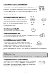
... dual high-speed Serial ATA interface ports. Power Power LED Switch 2 10 1 9 HDD Reset LED Switch JFP1 Speaker 2 8 1 7 Power LED JFP2 CD-In Connector: CD_IN1 The connector is used to a maximum throughput of 150MB/s and are 16550A high speed communication ports that the pins of VCC and GND must be connected correctly or it may cause some damage. Both are fully compliant with Intel Front Panel I/O Connectivity Design Guide. Front Panel Connectors: JFP1 & JFP2 The mainboard provides two front panel connectors for connecting high-speed USB...
... dual high-speed Serial ATA interface ports. Power Power LED Switch 2 10 1 9 HDD Reset LED Switch JFP1 Speaker 2 8 1 7 Power LED JFP2 CD-In Connector: CD_IN1 The connector is used to a maximum throughput of 150MB/s and are 16550A high speed communication ports that the pins of VCC and GND must be connected correctly or it may cause some damage. Both are fully compliant with Intel Front Panel I/O Connectivity Design Guide. Front Panel Connectors: JFP1 & JFP2 The mainboard provides two front panel connectors for connecting high-speed USB...
User Guide
Page 14
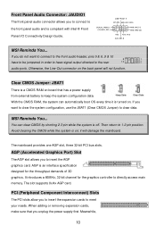
... to directly access main memory. AGP is compliant with Intel ® Front Panel I/O Connectivity Design Guide. The slot supports 8x/4x AGP card. If you to connect to clear data. Meanwhile, 10 MSI Reminds You... it is turned on board that you do not want to clear the system configuration, use the JBAT1 (Clear CMOS Jumper) to the front panel audio and is an interface specification designed for the graphics controller to 1-2 pin position. MSI Reminds You...
... to directly access main memory. AGP is compliant with Intel ® Front Panel I/O Connectivity Design Guide. The slot supports 8x/4x AGP card. If you to connect to clear data. Meanwhile, 10 MSI Reminds You... it is turned on board that you do not want to clear the system configuration, use the JBAT1 (Clear CMOS Jumper) to the front panel audio and is an interface specification designed for the graphics controller to 1-2 pin position. MSI Reminds You...
User Guide
Page 15
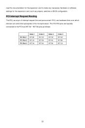
... Request Routing The IRQ, acronym of interrupt request line and pronounced I-R-Q, are typically connected to the PCI bus INT A# ~ INT D# pins as jumpers, switches or BIOS configuration. read the documentation for the expansion card to make any necessary hardware or software settings for the expansion card, such as follows: PCI Slot 1 PCI Slot 2 PCI Slot 3 Order 1 INT B# INT C# INT D# Order 2 INT C# INT D# INT A# Order 3 INT D# INT A# INT B# Order...
... Request Routing The IRQ, acronym of interrupt request line and pronounced I-R-Q, are typically connected to the PCI bus INT A# ~ INT D# pins as jumpers, switches or BIOS configuration. read the documentation for the expansion card to make any necessary hardware or software settings for the expansion card, such as follows: PCI Slot 1 PCI Slot 2 PCI Slot 3 Order 1 INT B# INT C# INT D# Order 2 INT C# INT D# INT A# Order 3 INT D# INT A# INT B# Order...
User Guide
Page 16
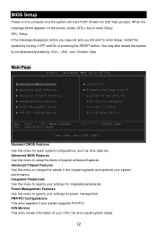
... Use this menu to setup the items of your CPU, fan and overall system status. 12 Advanced Chipset Features Use this menu to change the values in the chipset registers and optimize your settings for basic system configurations, such as time, date etc. Power Management Features Use this menu to specify your system performance. BIOS Setup Power on the screen, press key to enter Setup, restart the system by simultaneously pressing , , and keys. H/W Monitor...
... Use this menu to setup the items of your CPU, fan and overall system status. 12 Advanced Chipset Features Use this menu to change the values in the chipset registers and optimize your settings for basic system configurations, such as time, date etc. Power Management Features Use this menu to specify your system performance. BIOS Setup Power on the screen, press key to enter Setup, restart the system by simultaneously pressing , , and keys. H/W Monitor...
User Guide
Page 17
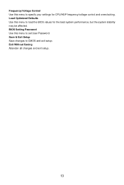
Load Optimized Defaults Use this menu to load the BIOS values for CPU/AGP frequency/voltage control and overclocking. Exit Without Saving Abandon all changes and exit setup. 13 Save & Exit Setup Save changes to specify your settings for the best system performance, but the system stability may be affected. BIOS Setting Password Use this menu to set User Password. Frequency/Voltage Control Use this menu to CMOS and exit setup.
Load Optimized Defaults Use this menu to load the BIOS values for CPU/AGP frequency/voltage control and overclocking. Exit Without Saving Abandon all changes and exit setup. 13 Save & Exit Setup Save changes to specify your settings for the best system performance, but the system stability may be affected. BIOS Setting Password Use this menu to set User Password. Frequency/Voltage Control Use this menu to CMOS and exit setup.
User Guide
Page 18
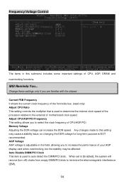
... setting allows you to select the clock frequency of the processor relative to determine the internal clock speed of CPU/AGP/PCI. Memory Voltage Adjusting the DDR voltage can increase the DDR speed. When set to [Enabled], the system will remove (turn off) clocks from empty DIMM/PCI slots to auto detect the DIMM/PCI slots. MSI Reminds You... Current FSB Frequency It shows the current clock frequency of the front side bus. (read only) Adjust CPU Ratio This setting controls...
... setting allows you to select the clock frequency of the processor relative to determine the internal clock speed of CPU/AGP/PCI. Memory Voltage Adjusting the DDR voltage can increase the DDR speed. When set to [Enabled], the system will remove (turn off) clocks from empty DIMM/PCI slots to auto detect the DIMM/PCI slots. MSI Reminds You... Current FSB Frequency It shows the current clock frequency of the front side bus. (read only) Adjust CPU Ratio This setting controls...

User Guide
Page 19
... by modulating the pulses so that the spikes of the pulses are overclocking because even a slight jitter can introduce a temporary boost in clockspeed which may just cause your overclocked processor to flatter curves. The Spread Spectrum function reduces the EMI generated by...Electromagnetic Interference). Spread Spectrum When the motherboard's clock generator pulses, the extreme values (spikes) of the options for optimal system stability and performance. Remember to disable Spread Spectrum if you do not have any EMI problem, leave the setting at Disabled for EMI reduction. If you ...
... by modulating the pulses so that the spikes of the pulses are overclocking because even a slight jitter can introduce a temporary boost in clockspeed which may just cause your overclocked processor to flatter curves. The Spread Spectrum function reduces the EMI generated by...Electromagnetic Interference). Spread Spectrum When the motherboard's clock generator pulses, the extreme values (spikes) of the options for optimal system stability and performance. Remember to disable Spread Spectrum if you do not have any EMI problem, leave the setting at Disabled for EMI reduction. If you ...
User Guide
Page 61
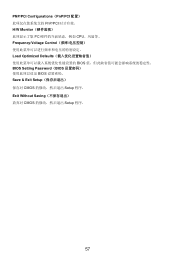
PNP/PCI Configurations(PnP/PCI PnP/PCI H/W Monitor PC CPU Frequency/Voltage Control Load Optimized Defaults BIOS BIOS Setting Password(BIOS BIOS Save & Exit Setup CMOS Setup 程序。 Exit Without Saving CMOS Setup 程序。 57
PNP/PCI Configurations(PnP/PCI PnP/PCI H/W Monitor PC CPU Frequency/Voltage Control Load Optimized Defaults BIOS BIOS Setting Password(BIOS BIOS Save & Exit Setup CMOS Setup 程序。 Exit Without Saving CMOS Setup 程序。 57
User Guide
Page 72
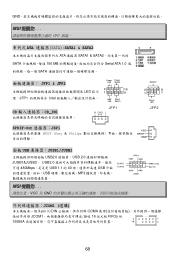
... & SATA2 ATA 連接器 SATA1 & SATA2 SATA 150 MB Serial ATA 1.0 SATA JFP1 & JFP2 LED JFP1 Intel CD CD_IN1 Power Power LED Switch 2 10 1 9 HDD Reset LED Switch JFP1 SPDIF-Out JSP1 SPDIF (Sony 及 Philips Speaker 2 8 1 7 Power LED JFP2 面板 USB JUSB1/JUSB2 USB2.0 USB 2.0 JUSB1&JUSB2。 USB2.0 480Mbps USB 1.1 的 40 USB USB MP3 MSI VCC 及 GND JCOM1 (選購) 9-pin 的 DIN COMA JCOM1 16 位元...
... & SATA2 ATA 連接器 SATA1 & SATA2 SATA 150 MB Serial ATA 1.0 SATA JFP1 & JFP2 LED JFP1 Intel CD CD_IN1 Power Power LED Switch 2 10 1 9 HDD Reset LED Switch JFP1 SPDIF-Out JSP1 SPDIF (Sony 及 Philips Speaker 2 8 1 7 Power LED JFP2 面板 USB JUSB1/JUSB2 USB2.0 USB 2.0 JUSB1&JUSB2。 USB2.0 480Mbps USB 1.1 的 40 USB USB MP3 MSI VCC 及 GND JCOM1 (選購) 9-pin 的 DIN COMA JCOM1 16 位元...

User Guide
Page 76
BIOS Setting Password(BIOS BIOS 密碼。 Save & Exit Setup CMOS Exit Without Saving CMOS 72
BIOS Setting Password(BIOS BIOS 密碼。 Save & Exit Setup CMOS Exit Without Saving CMOS 72
User Guide
Page 89
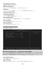
Power Management Features PNP/PCI Configurations PCI H/W Monitor CPU Frequency/Voltage Control Load Optimized Defaults BIOS Setting Password BIOS Save & Exit Setup BIOS Exit Without Saving Frequency/Voltage Control CPU / AGP / DRAM ●「Frequency/Voltage Control Current FSB Frequency 現在の FSB Adjust CPU Ratio CPU 8 倍から 50 85
Power Management Features PNP/PCI Configurations PCI H/W Monitor CPU Frequency/Voltage Control Load Optimized Defaults BIOS Setting Password BIOS Save & Exit Setup BIOS Exit Without Saving Frequency/Voltage Control CPU / AGP / DRAM ●「Frequency/Voltage Control Current FSB Frequency 現在の FSB Adjust CPU Ratio CPU 8 倍から 50 85


