
User Guide
Page 4
... interference by the party responsible for a Class B digital device, pursuant to Part 15 of the FCC Rules. Notice 2 Shielded interface cables and A.C. Micro-Star International MS-7235 This device complies with the instructions, may cause undesired operation. power cord, if any, must accept any interference received, including interference that may cause harmful...
... interference by the party responsible for a Class B digital device, pursuant to Part 15 of the FCC Rules. Notice 2 Shielded interface cables and A.C. Micro-Star International MS-7235 This device complies with the instructions, may cause undesired operation. power cord, if any, must accept any interference received, including interference that may cause harmful...

User Guide
Page 11
...processors in the LGA775 package - php) Supported FSB - 1066/ 800/ 533 MHz Chipset - msi.com.tw/program/products/mainboard/mbd/pro_m bd_trp_list.php) LAN - Flexible 8-channel audio with 360K...) - 2 1394 ports by Marvell 88SE6111 - Supports EIST Technology - North Bridge: Intel® P965/ G965 chipset - Chip integrated by Marvell 88SE6111 - Supports PIO, Bus Master operation mode SATA -...Spec - Supports PCI LAN 10/100/1000 Fast Ethernet by Realtek 8110SC Audio - MS-7235 Mainboard Mainboard Specifications Processor Support - Supports Intel Quad Core / Dual Core Technology up...
...processors in the LGA775 package - php) Supported FSB - 1066/ 800/ 533 MHz Chipset - msi.com.tw/program/products/mainboard/mbd/pro_m bd_trp_list.php) LAN - Flexible 8-channel audio with 360K...) - 2 1394 ports by Marvell 88SE6111 - Supports EIST Technology - North Bridge: Intel® P965/ G965 chipset - Chip integrated by Marvell 88SE6111 - Supports PIO, Bus Master operation mode SATA -...Spec - Supports PCI LAN 10/100/1000 Fast Ethernet by Realtek 8110SC Audio - MS-7235 Mainboard Mainboard Specifications Processor Support - Supports Intel Quad Core / Dual Core Technology up...

User Guide
Page 13
... NB FA N1 RTL8110SC PCIE2 Intel P965/ G965 VT 63 08 P (optional) PCIE3 Intel ICH8 ALC888 PCI 1 PCI 2 JSP I1 BATT + JAUD1 CD_IN1 J1394_1 (optional) JSPD1 (optional) FDD1 JUSB2 JUSB3 JBAT1 JUSB4 JFP1 P965Neo-F V2 Series (MS-7235 v2.X) ATX Mainboard 1-4 SATA7 IDE1 SATA4 SATA3 SATA2 SATA1 JFP2 MS-7235 Mainboard Mainboard Layout Top : mouse Bottom...
... NB FA N1 RTL8110SC PCIE2 Intel P965/ G965 VT 63 08 P (optional) PCIE3 Intel ICH8 ALC888 PCI 1 PCI 2 JSP I1 BATT + JAUD1 CD_IN1 J1394_1 (optional) JSPD1 (optional) FDD1 JUSB2 JUSB3 JBAT1 JUSB4 JFP1 P965Neo-F V2 Series (MS-7235 v2.X) ATX Mainboard 1-4 SATA7 IDE1 SATA4 SATA3 SATA2 SATA1 JFP2 MS-7235 Mainboard Mainboard Layout Top : mouse Bottom...

User Guide
Page 15
... the left and right sides, two sub-menus will open for users to adjust the thresholds of system to send out the warning messages. 1-6 MS-7235 Mainboard MSI Special Feature The Core Center is just like your PC doctor that can find in the left side it shows the current PC hardware status...
... the left and right sides, two sub-menus will open for users to adjust the thresholds of system to send out the warning messages. 1-6 MS-7235 Mainboard MSI Special Feature The Core Center is just like your PC doctor that can find in the left side it shows the current PC hardware status...

User Guide
Page 20
.... Meanwhile, do not have the cooler, contact your CPU & mainboard. 1. Remove the cap from damage. Follow the steps below to install the CPU & cooler correctly. MS-7235 Mainboard CPU & Cooler Installation W hen you are installing the CPU, make sure the CPU has a cooler attached on it to protect the socket pin. 2.
.... Meanwhile, do not have the cooler, contact your CPU & mainboard. 1. Remove the cap from damage. Follow the steps below to install the CPU & cooler correctly. MS-7235 Mainboard CPU & Cooler Installation W hen you are installing the CPU, make sure the CPU has a cooler attached on it to protect the socket pin. 2.

User Guide
Page 22
... the locking switch (refer to avoid damaging. 2-6 Whenever CPU is not installed, always protect your CPU socket pin with the hook under retention tab. 10. MS-7235 Mainboard 9. Press down the load lever lightly onto the load plate, and then secure the lever with the plastic cap covered (shown in H/W M onitor of...
... the locking switch (refer to avoid damaging. 2-6 Whenever CPU is not installed, always protect your CPU socket pin with the hook under retention tab. 10. MS-7235 Mainboard 9. Press down the load lever lightly onto the load plate, and then secure the lever with the plastic cap covered (shown in H/W M onitor of...

User Guide
Page 24
... orientation. 2. In dual-channel mode, make sure that you install memory modules of the DIMM slot will only fit in different channel DDR DIMM slots. - MS-7235 Mainboard Installing DDRII Modules 1. The memory module has only one notch on the memory module is deeply inserted in until the golden finger on the...
... orientation. 2. In dual-channel mode, make sure that you install memory modules of the DIMM slot will only fit in different channel DDR DIMM slots. - MS-7235 Mainboard Installing DDRII Modules 1. The memory module has only one notch on the memory module is deeply inserted in until the golden finger on the...

User Guide
Page 26
... Indicator LED Color Left Orange Green Right Orange LED State Condition Off LAN link is selected. On 100 Mbit/sec data rate is not established. MS-7235 Mainboard Back Panel Mouse Parallel Port IEEE1394 LAN (optional) L-In RS-Out L-Out CS-Out Keyboard Serial Port VGA Port (G965 only) USB Ports Mic...
... Indicator LED Color Left Orange Green Right Orange LED State Condition Off LAN link is selected. On 100 Mbit/sec data rate is not established. MS-7235 Mainboard Back Panel Mouse Parallel Port IEEE1394 LAN (optional) L-In RS-Out L-Out CS-Out Keyboard Serial Port VGA Port (G965 only) USB Ports Mic...

User Guide
Page 28
... Master IDE controller that supports PIO mode 0~4, Bus Master, and Ultra DMA 66/100/133 function. Refer to Slave mode by setting the jumper accordingly. MS-7235 Mainboard Connectors Floppy Disk Drive Connector: FDD1 This standard FDD connector supports 360K, 720K, 1.2M, 1.44M and 2.88M floppy disk types. You can connect a Master...
... Master IDE controller that supports PIO mode 0~4, Bus Master, and Ultra DMA 66/100/133 function. Refer to Slave mode by setting the jumper accordingly. MS-7235 Mainboard Connectors Floppy Disk Drive Connector: FDD1 This standard FDD connector supports 360K, 720K, 1.2M, 1.44M and 2.88M floppy disk types. You can connect a Master...

User Guide
Page 30
... SENSOR +1 2V CPUFAN1 SE NS OR +1 2V GND NBFAN1 GND SE NS OR +1 2V SYSFAN1 Important 1. If the chassis is Ground and should be short. MS-7235 Mainboard Fan Power Connectors: CPUFAN1, NBFAN1, SYSFAN1 The fan power connectors support system cooling fan with speed sensor to take note that will record this...
... SENSOR +1 2V CPUFAN1 SE NS OR +1 2V GND NBFAN1 GND SE NS OR +1 2V SYSFAN1 Important 1. If the chassis is Ground and should be short. MS-7235 Mainboard Fan Power Connectors: CPUFAN1, NBFAN1, SYSFAN1 The fan power connectors support system cooling fan with speed sensor to take note that will record this...
User Guide
Page 32
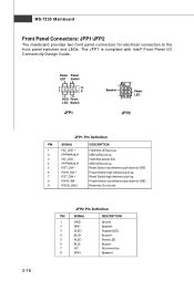
... Power Switch high reference pull-up Reset Switch high reference pull-up Power Switch low reference pull-down to the front panel switches and LEDs. MS-7235 Mainboard Front Panel Connectors: JFP1/JFP2 The mainboard provides two front panel connectors for electrical connection to GND Reserved. The JFP1 is compliant with Intel...
... Power Switch high reference pull-up Reset Switch high reference pull-up Power Switch low reference pull-down to the front panel switches and LEDs. MS-7235 Mainboard Front Panel Connectors: JFP1/JFP2 The mainboard provides two front panel connectors for electrical connection to GND Reserved. The JFP1 is compliant with Intel...

User Guide
Page 34
... 1 9 Pin Definition PIN SIGNAL 1 VCC 3 USB0- 5 USB0+ 7 GND 9 Key (no pin) PIN SIGNAL 2 VCC 4 USB1- 6 USB1+ 8 GND 10 USBOC Connected to avoid possible damage. 2-18 MS-7235 Mainboard Front USB Connectors: JUSB2, JUSB3, JUSB4 The mainboard provides three USB 2.0 pinheaders (optional USB 2.0 bracket available) that the pins of 480Mbps, which is 40...
... 1 9 Pin Definition PIN SIGNAL 1 VCC 3 USB0- 5 USB0+ 7 GND 9 Key (no pin) PIN SIGNAL 2 VCC 4 USB1- 6 USB1+ 8 GND 10 USBOC Connected to avoid possible damage. 2-18 MS-7235 Mainboard Front USB Connectors: JUSB2, JUSB3, JUSB4 The mainboard provides three USB 2.0 pinheaders (optional USB 2.0 bracket available) that the pins of 480Mbps, which is 40...

User Guide
Page 36
... return to clear data. it is off. With the CMOS RAM, the system can clear CMOS by shorting 2-3 pin while the system is turned on ; MS-7235 Mainboard Jumpers Clear CMOS Jumper: JBAT1 There is on .
... return to clear data. it is off. With the CMOS RAM, the system can clear CMOS by shorting 2-3 pin while the system is turned on ; MS-7235 Mainboard Jumpers Clear CMOS Jumper: JBAT1 There is on .
User Guide
Page 38
... typically connected to configure any necessary hardware or software settings for the expansion card to the PCI bus pins as jumpers, switches or BIOS configuration. MS-7235 Mainboard Important When adding or removing expansion cards, make sure that you unplug the power supply first.
... typically connected to configure any necessary hardware or software settings for the expansion card to the PCI bus pins as jumpers, switches or BIOS configuration. MS-7235 Mainboard Important When adding or removing expansion cards, make sure that you unplug the power supply first.

User Guide
Page 40
... digit refers to the model number. 6th digit refers to the chipset as I = Intel, N = nVidia, and V = VIA. 7th - 8th digit refers to the customer as MS = all standard customers. You may be slightly different from the latest BIOS and should be held for better system performance. Upon boot-up, the 1st...
... digit refers to the model number. 6th digit refers to the chipset as I = Intel, N = nVidia, and V = VIA. 7th - 8th digit refers to the customer as MS = all standard customers. You may be slightly different from the latest BIOS and should be held for better system performance. Upon boot-up, the 1st...

User Guide
Page 42
... settings for basic system configurations, such as time, date etc. Cell Menu Use this menu to setup the items of AWARD® special enhanced features. MS-7235 Mainboard The Main Menu Standard CMOS Features Use this menu for CPU/AGP frequency/voltage control and overclocking. 3-4 Advanced Chipset Features Use this menu to...
... settings for basic system configurations, such as time, date etc. Cell Menu Use this menu to setup the items of AWARD® special enhanced features. MS-7235 Mainboard The Main Menu Standard CMOS Features Use this menu for CPU/AGP frequency/voltage control and overclocking. 3-4 Advanced Chipset Features Use this menu to...

User Guide
Page 44
... date). The specification of the week, from Jan. If detection is successful, it fills the remaining fields on the right hand according to your selection. MS-7235 Mainboard Standard CMOS Features The items in each item: IDE HDD Auto-Detection Press Enter to auto-detect the HDD on this menu. 3-6 IDE Primary...
... date). The specification of the week, from Jan. If detection is successful, it fills the remaining fields on the right hand according to your selection. MS-7235 Mainboard Standard CMOS Features The items in each item: IDE HDD Auto-Detection Press Enter to auto-detect the HDD on this menu. 3-6 IDE Primary...

User Guide
Page 46
... only one core to execute the instructions. The technology treats the two cores inside the processor as two logical processors that can execute instructions simultaneously. MS-7235 Mainboard Advanced BIOS Features Full Screen LOGO Display This item enables you disable the function, the processor will use the arrow keys on the numeric...
... only one core to execute the instructions. The technology treats the two cores inside the processor as two logical processors that can execute instructions simultaneously. MS-7235 Mainboard Advanced BIOS Features Full Screen LOGO Display This item enables you disable the function, the processor will use the arrow keys on the numeric...

User Guide
Page 48
.... Configure DRAM Timing by SPD Selects whether DRAM timing is reserved, it cannot be determined by the SPD (Serial Presence Detect) EEPROM on the SPD. MS-7235 Mainboard Advanced Chipset Features Important Change these settings only if you are familiar with the chipset. Setting to improve performance, certain space in memory can...
.... Configure DRAM Timing by SPD Selects whether DRAM timing is reserved, it cannot be determined by the SPD (Serial Presence Detect) EEPROM on the SPD. MS-7235 Mainboard Advanced Chipset Features Important Change these settings only if you are familiar with the chipset. Setting to improve performance, certain space in memory can...
User Guide
Page 50
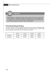
.... To operate the onboard parallel port in this field. Parallel Port IRQ This item allows you could use the other IRQs (except IRQ14 and IRQ15). MS-7235 Mainboard SATA#1 Configuration This item allows you to configurare IDE device mode. [Compatible] If Compatible selected, Legacy IDE Channels will only use IRQ14 and IRQ15...
.... To operate the onboard parallel port in this field. Parallel Port IRQ This item allows you could use the other IRQs (except IRQ14 and IRQ15). MS-7235 Mainboard SATA#1 Configuration This item allows you to configurare IDE device mode. [Compatible] If Compatible selected, Legacy IDE Channels will only use IRQ14 and IRQ15...


