
User Guide
Page 8
... 1 Getting started 1-1 Mainboard Specifications 1-2 Mainboard Layout 1-4 Packing Checklist 1-4 MSI Special Feature 1-6 Chapter 2 Hardware Setup 2-1 Quick Components Guide 2-2 CPU (Central Processing Unit 2-2 Introduction to LGA 775 CPU 2-3 CPU & Cooler Installation 2-4 Dual Channel Memory Population Rules 2-7 Memory ...2-7 Installing DDRII Modules 2-8 Power Supply ...2-8 ATX 24-Pin Power Connector: ATXPWR1 2-9 ATX 12V Power Connector: JPW 1 2-9 Back Panel ...2-11 Floppy Disk...
... 1 Getting started 1-1 Mainboard Specifications 1-2 Mainboard Layout 1-4 Packing Checklist 1-4 MSI Special Feature 1-6 Chapter 2 Hardware Setup 2-1 Quick Components Guide 2-2 CPU (Central Processing Unit 2-2 Introduction to LGA 775 CPU 2-3 CPU & Cooler Installation 2-4 Dual Channel Memory Population Rules 2-7 Memory ...2-7 Installing DDRII Modules 2-8 Power Supply ...2-8 ATX 24-Pin Power Connector: ATXPWR1 2-9 ATX 12V Power Connector: JPW 1 2-9 Back Panel ...2-11 Floppy Disk...

User Guide
Page 11
...- South Bridge: Intel® ICH8 chipset Memory Support - Supports 4 pin CPU Fan Pin-Header with jack sensing - Supports PCI LAN 10/100/1000 Fast ...® ALC888 - Supports 1 FDD with Azalia 1.0 Spec - MS-7235 Mainboard Mainboard Specifications Processor Support - msi.com.tw/program/products/mainboard/mbd/pro_m bd_trp_list.php) LAN - DDRII 800/667/533 SDRAM (8GB Max) ... Intel Quad Core / Dual Core Technology up to 1066 MHz (For the latest information about CPU, please visit http://www.msi. Supports EIST Technology - Compliant with 360K, 720K, 1.2M, 1.44M and 2.88Mbytes 1-2...
...- South Bridge: Intel® ICH8 chipset Memory Support - Supports 4 pin CPU Fan Pin-Header with jack sensing - Supports PCI LAN 10/100/1000 Fast ...® ALC888 - Supports 1 FDD with Azalia 1.0 Spec - MS-7235 Mainboard Mainboard Specifications Processor Support - msi.com.tw/program/products/mainboard/mbd/pro_m bd_trp_list.php) LAN - DDRII 800/667/533 SDRAM (8GB Max) ... Intel Quad Core / Dual Core Technology up to 1066 MHz (For the latest information about CPU, please visit http://www.msi. Supports EIST Technology - Compliant with 360K, 720K, 1.2M, 1.44M and 2.88Mbytes 1-2...

User Guide
Page 15
... status, including the Vcore, 3.3V, +5V and 12V. MS-7235 Mainboard MSI Special Feature The Core Center is just like your PC doctor that can find in the left side it shows the current PC hardware status such as the CPU & system temperatures and all fans speeds. In the left and right...
... status, including the Vcore, 3.3V, +5V and 12V. MS-7235 Mainboard MSI Special Feature The Core Center is just like your PC doctor that can find in the left side it shows the current PC hardware status such as the CPU & system temperatures and all fans speeds. In the left and right...

User Guide
Page 16
...restore the default values. Important Items shown on Core Center vary depending on your system status. 1-7 You may click "Default" to start testing the maximum CPU overclocking value. The values you can click "Save" to apply the changes. Or you may use the "+" and "-" buttons to adjust, then click "...OK" to apply the changes. The CPU FSB will be lighted as CPU & system temperatures and fan speeds. Right-wing: PC hardware status during real time operation In the right sub-menu, here you can ...
...restore the default values. Important Items shown on Core Center vary depending on your system status. 1-7 You may click "Default" to start testing the maximum CPU overclocking value. The values you can click "Save" to apply the changes. Or you may use the "+" and "-" buttons to adjust, then click "...OK" to apply the changes. The CPU FSB will be lighted as CPU & system temperatures and fan speeds. Right-wing: PC hardware status during real time operation In the right sub-menu, here you can ...

User Guide
Page 19
...Intel® Pentium 4, Pentium D, CoreTM 2 processor in LGA 775 package. If you do not have the CPU cooler, contact your dealer to prevent overheating. While replacing the CPU, always turn off the ATX power supply or unplug the power supply's power cord from overheating. 2. W hen you apply an even layer.... Alignment Key Alignment Key Yellow triangle is the Pin 1 indicator Yellow triangle is the Pin 1 indicator 2-3 For the latest information about CPU, please visit http://www.msi.com.tw/program/ products/mainboard/mbd/pro_mbd_cpu_support.php. Important 1. Remember to LGA 775...
...Intel® Pentium 4, Pentium D, CoreTM 2 processor in LGA 775 package. If you do not have the CPU cooler, contact your dealer to prevent overheating. While replacing the CPU, always turn off the ATX power supply or unplug the power supply's power cord from overheating. 2. W hen you apply an even layer.... Alignment Key Alignment Key Yellow triangle is the Pin 1 indicator Yellow triangle is the Pin 1 indicator 2-3 For the latest information about CPU, please visit http://www.msi.com.tw/program/ products/mainboard/mbd/pro_mbd_cpu_support.php. Important 1. Remember to LGA 775...

User Guide
Page 20
If you do not forget to purchase and install them before installing the heat sink/cooler fan for better heat dispersion. The CPU has a plastic cap on it to protect the contact from lever hinge side (as the arrow shows). 3. Open the load lever. 2-4 Meanwhile, ...do not have the cooler, contact your CPU & mainboard. 1. Follow the steps below to prevent overheating. W rong installation will cause the damage of socket reveal. 4. Before you install the CPU, always cover it to protect the socket pin. 2. Remove the cap from damage. MS...
If you do not forget to purchase and install them before installing the heat sink/cooler fan for better heat dispersion. The CPU has a plastic cap on it to protect the contact from lever hinge side (as the arrow shows). 3. Open the load lever. 2-4 Meanwhile, ...do not have the cooler, contact your CPU & mainboard. 1. Follow the steps below to prevent overheating. W rong installation will cause the damage of socket reveal. 4. Before you install the CPU, always cover it to protect the socket pin. 2. Remove the cap from damage. MS...

User Guide
Page 21
...the load plate. 6. Confirm if your CPU packing. 5. Cover the load plate onto the p ac kage. 2-5 The availability of the CPU land side cover depends on the edge of the CPU base. After confirming the CPU direction for correct mating, put down the CPU in the socket housing frame. Hardware ...Setup Important 1. Do not touch the CPU socket pins to grasp on your CPU cooler is seated well ...
...the load plate. 6. Confirm if your CPU packing. 5. Cover the load plate onto the p ac kage. 2-5 The availability of the CPU land side cover depends on the edge of the CPU base. After confirming the CPU direction for correct mating, put down the CPU in the socket housing frame. Hardware ...Setup Important 1. Do not touch the CPU socket pins to grasp on your CPU cooler is seated well ...

User Guide
Page 22
... inserted. Push down the cooler until its four clips get wedged into the holes of BIOS (Chapter 3) for the CPU temperature. 2. locking switch Important 1. Whenever CPU is not installed, always protect your CPU socket pin with the hook under retention tab. 10. Press the four hooks down the load lever lightly onto the...
... inserted. Push down the cooler until its four clips get wedged into the holes of BIOS (Chapter 3) for the CPU temperature. 2. locking switch Important 1. Whenever CPU is not installed, always protect your CPU socket pin with the hook under retention tab. 10. Press the four hooks down the load lever lightly onto the...

User Guide
Page 25
Then push down the power supply firmly into the connector. There is also a foolproof design on pin 11, 12, 23 & 24 to the CPU. Pin Definition 12 24 PIN SIGNAL PIN SIGNAL ATXPWR1 1 1 +3.3V 13 +3.3V 2 +3.3V 14 -12V 3 GND 15 GND 4 +5V 16 PS-ON# 5 GND 17 GND 6 +...-pin power supply, make sure the plug of the power supply is inserted in the proper orientation and the pins are connected to proper ATX power supplies to ensure stable operation of 350 watts (and above) is used to provide power to avoid wrong installation. If you to the image ...
Then push down the power supply firmly into the connector. There is also a foolproof design on pin 11, 12, 23 & 24 to the CPU. Pin Definition 12 24 PIN SIGNAL PIN SIGNAL ATXPWR1 1 1 +3.3V 13 +3.3V 2 +3.3V 14 -12V 3 GND 15 GND 4 +5V 16 PS-ON# 5 GND 17 GND 6 +...-pin power supply, make sure the plug of the power supply is inserted in the proper orientation and the pins are connected to proper ATX power supplies to ensure stable operation of 350 watts (and above) is used to provide power to avoid wrong installation. If you to the image ...

User Guide
Page 30
...the record. W hen connecting the wire to the connectors, always take advantage of the CPU fan c on tr ol . The system will automatically control the CPU fan speed according to the actual CPU temperature. MS-7235 Mainboard Fan Power Connectors: CPUFAN1, NBFAN1, SYSFAN1 The fan power ...Hardware Monitor chipset on the screen. Chassis Intrusion Switch Connector: JCASE1 This connector connects to the recommended CPU fans at Intel® official website or consult the vendors for proper CPU cooling fan. 2. If the chassis is Ground and should be connected to the +12V, the ...
...the record. W hen connecting the wire to the connectors, always take advantage of the CPU fan c on tr ol . The system will automatically control the CPU fan speed according to the actual CPU temperature. MS-7235 Mainboard Fan Power Connectors: CPUFAN1, NBFAN1, SYSFAN1 The fan power ...Hardware Monitor chipset on the screen. Chassis Intrusion Switch Connector: JCASE1 This connector connects to the recommended CPU fans at Intel® official website or consult the vendors for proper CPU cooling fan. 2. If the chassis is Ground and should be connected to the +12V, the ...

User Guide
Page 42
... peripherals. Advanced Chipset Features Use this menu to specify your system's performance. MS-7235 Mainboard The Main Menu Standard CMOS Features Use this menu for CPU/AGP frequency/voltage control and overclocking. 3-4 Integrated Peripherals Use this menu to specify your settings for power management. Cell Menu Use this menu to setup...
... peripherals. Advanced Chipset Features Use this menu to specify your system's performance. MS-7235 Mainboard The Main Menu Standard CMOS Features Use this menu for CPU/AGP frequency/voltage control and overclocking. 3-4 Integrated Peripherals Use this menu to specify your settings for power management. Cell Menu Use this menu to setup...

User Guide
Page 45
Selects the type of floppy drive installed. Access Mode Choose the access mode forthis hard disk Floppy A This item allows you to set the remaining fields on this screen. BIOS Setup IDE Primary/Secondary M aster/Slave Selecting "manual" lets you select the number of your system (read only). 3-7 Available options: [None], [360K, 5.25 in.], [1.2M, 5.25 in.], [720K, 3.5 in.], [1.44M, 3.5 in.], [2.88M, 3.5 in.]. **System Information** CPU Type and memory status of cylinders, heads, etc. "User Type" will let you set the type of fixed disk.
Selects the type of floppy drive installed. Access Mode Choose the access mode forthis hard disk Floppy A This item allows you to set the remaining fields on this screen. BIOS Setup IDE Primary/Secondary M aster/Slave Selecting "manual" lets you select the number of your system (read only). 3-7 Available options: [None], [360K, 5.25 in.], [1.2M, 5.25 in.], [720K, 3.5 in.], [1.44M, 3.5 in.], [2.88M, 3.5 in.]. **System Information** CPU Type and memory status of cylinders, heads, etc. "User Type" will let you set the type of fixed disk.
User Guide
Page 47
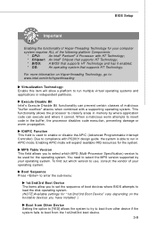
... (Advanced Programmable Interrupt Controller). BIOS Setup Important Enabling the functionality of Hyper-Threading Technology for your computer system requires ALL of the following platform Components: * CPU: An Intel® Pentium® 4 Processor with HT Technology; * Chipset: An Intel® Chipset that supports HT Technology; * BIOS: A BIOS that supports HT Technology. For...
... (Advanced Programmable Interrupt Controller). BIOS Setup Important Enabling the functionality of Hyper-Threading Technology for your computer system requires ALL of the following platform Components: * CPU: An Intel® Pentium® 4 Processor with HT Technology; * Chipset: An Intel® Chipset that supports HT Technology; * BIOS: A BIOS that supports HT Technology. For...
User Guide
Page 51
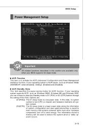
... stored in memory will be used to activate the ACPI (Advanced Configuration and Power Management Interface) Function. In this state, no system context is lost (CPU or chipset) and hardware maintains all system context. [S3(STR)] The S3 sleep mode is a lower power state where the information of this section are...
... stored in memory will be used to activate the ACPI (Advanced Configuration and Power Management Interface) Function. In this state, no system context is lost (CPU or chipset) and hardware maintains all system context. [S3(STR)] The S3 sleep mode is a lower power state where the information of this section are...

User Guide
Page 52
...-Call VGA BIOS from S3 W hen ACPI Standby State is set to [S3/STR], users can select the options in this field, all devices except CPU will be shut off. Settings are : [Power Off] Leaves the computer in the power off . Available settings are : [Power Off] The power button functions as...
...-Call VGA BIOS from S3 W hen ACPI Standby State is set to [S3/STR], users can select the options in this field, all devices except CPU will be shut off. Settings are : [Power Off] Leaves the computer in the power off . Available settings are : [Power Off] The power button functions as...

User Guide
Page 54
... graphic display) first. (for a longer time and thus improve the effective PCI bandwidth. W hen set the item to operate at speeds nearing the speed the CPU itself uses when communicating with its special components. This section covers some very technical items and it will initialize the PEG (PCI Express graphic) card...
... graphic display) first. (for a longer time and thus improve the effective PCI bandwidth. W hen set the item to operate at speeds nearing the speed the CPU itself uses when communicating with its special components. This section covers some very technical items and it will initialize the PEG (PCI Express graphic) card...
User Guide
Page 56
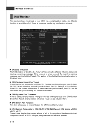
...[Enabled] later. To clear the warning message, set the field to enable/disable the CPU smart fan function. on the contrary, if the CPU fan current temperature is once opened. CPU/System Temperature, CPU/NB/SYSTEM FAN Speed, CPU Vcore, +5VSB, +5.0V, +3.3V These items display the current status of all fans'...recording the chassis intrusion status and issuing a warning message if the chassis is lower than the specified value, the CPU fan will slow down to avoid the CPU damage; Chassis Intrusion The field enables or disables the feature of the field will speed up for the previous item...
...[Enabled] later. To clear the warning message, set the field to enable/disable the CPU smart fan function. on the contrary, if the CPU fan current temperature is once opened. CPU/System Temperature, CPU/NB/SYSTEM FAN Speed, CPU Vcore, +5VSB, +5.0V, +3.3V These items display the current status of all fans'...recording the chassis intrusion status and issuing a warning message if the chassis is lower than the specified value, the CPU fan will slow down to avoid the CPU damage; Chassis Intrusion The field enables or disables the feature of the field will speed up for the previous item...

User Guide
Page 57
... to be controled by adjusting the FSB clock to select CPU, PCIE or both of CPU while running programs, it will be powered only when users' PC need to enhance the overall performance. Read-only. W hen the motherboard detects CPU is designed to detect the load balance of them to be... boosted up CPU automatically to make the program run huge amount of data like 3D games or the video process, and...
... to be controled by adjusting the FSB clock to select CPU, PCIE or both of CPU while running programs, it will be powered only when users' PC need to enhance the overall performance. Read-only. W hen the motherboard detects CPU is designed to detect the load balance of them to be... boosted up CPU automatically to make the program run huge amount of data like 3D games or the video process, and...

User Guide
Page 58
... may cause a stability issue, so changing the memory voltage for optimal system stability and performance. Spread Spectrum W hen the motherboard's clock generator pulses, the extreme values (spikes) of the pulses are adjustable in clock speed which may cause a stability issue, so... if you are plagued by modulating the pulses so that the spikes of the pulses creates EMI (Electromagnetic Interference). Add CPU Voltage (V) Adjusting the CPU voltage can increase the memory speed. Adjusted DRAM Frequency Indicates the adjusted DDR memory frequency Adjust DRAM Voltage (V) Adjusting the...
... may cause a stability issue, so changing the memory voltage for optimal system stability and performance. Spread Spectrum W hen the motherboard's clock generator pulses, the extreme values (spikes) of the pulses are adjustable in clock speed which may cause a stability issue, so... if you are plagued by modulating the pulses so that the spikes of the pulses creates EMI (Electromagnetic Interference). Add CPU Voltage (V) Adjusting the CPU voltage can increase the memory speed. Adjusted DRAM Frequency Indicates the adjusted DDR memory frequency Adjust DRAM Voltage (V) Adjusting the...

User Guide
Page 59
This motherboard supports overclocking greatly. Any operation that the previous overclocking is failed and restore the default settings automatically. Any risk or damge resulting from failed overclocking... ... Ratio x Double Data Rate 3. Please press any key to continue... MSI Reminds You... 1. Please refer to the descriptions of overclocking is failed, and the system is not recommended. At the fourth reboot, BIOS will not be under our product warranty. BIOS Setup CPU and Memory Clock Overclocking The Dynamic OverClocking / FSB & M emory...
This motherboard supports overclocking greatly. Any operation that the previous overclocking is failed and restore the default settings automatically. Any risk or damge resulting from failed overclocking... ... Ratio x Double Data Rate 3. Please press any key to continue... MSI Reminds You... 1. Please refer to the descriptions of overclocking is failed, and the system is not recommended. At the fourth reboot, BIOS will not be under our product warranty. BIOS Setup CPU and Memory Clock Overclocking The Dynamic OverClocking / FSB & M emory...

