User Guide
Page 2
.... Intel® and Pentium® are under continual improvement and we reserve the right to the correctness of purchase or local distributor. Visit the MSI website for further guidance. Award® is a registered trademark of American Megatrends Inc. AMD, Athlon™, Athlon™ XP, Thoroughbred™, and...registered trademark of Novell, Inc. Netware® is given as to make changes without notice. Revision History Revision V1.1 Revision History Update memory capacity Date October 2008 Technical Support If a problem arises with your place of its contents.
.... Intel® and Pentium® are under continual improvement and we reserve the right to the correctness of purchase or local distributor. Visit the MSI website for further guidance. Award® is a registered trademark of American Megatrends Inc. AMD, Athlon™, Athlon™ XP, Thoroughbred™, and...registered trademark of Novell, Inc. Netware® is given as to make changes without notice. Revision History Revision V1.1 Revision History Update memory capacity Date October 2008 Technical Support If a problem arises with your place of its contents.
User Guide
Page 8
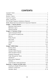
... Instructions ...iii FCC-B Radio Frequency Interference Statement iv W EEE (Waste Electrical and Electronic Equipment) Statement v Chapter 1. Hardware Setup 2-1 Quick Components Guide 2-2 CPU (Central Processing Unit 2-3 Memory ...2-7 Power Supply ...2-9 Back Panel ...2-11 Connectors ...2-13 Jumper ...2-20 Slots ...2-21 Chapter 3 BIOS Setup 3-1 Entering Setup ...3-2 The Main Menu ...3-4 Standard CMOS Features 3-6 Advanced BIOS Features...
... Instructions ...iii FCC-B Radio Frequency Interference Statement iv W EEE (Waste Electrical and Electronic Equipment) Statement v Chapter 1. Hardware Setup 2-1 Quick Components Guide 2-2 CPU (Central Processing Unit 2-3 Memory ...2-7 Power Supply ...2-9 Back Panel ...2-11 Connectors ...2-13 Jumper ...2-20 Slots ...2-21 Chapter 3 BIOS Setup 3-1 Entering Setup ...3-2 The Main Menu ...3-4 Standard CMOS Features 3-6 Advanced BIOS Features...

User Guide
Page 11
NVIDIA® nForce 730i (MCP7A) Memory Support - t w / i ndex. Chip integrated by Realtek ALC888 - c om . fu nc =t es t r ep or t ) LAN - Supports transfer rate up to 400Mbps Audio - Supports Intel® Hyper-...
NVIDIA® nForce 730i (MCP7A) Memory Support - t w / i ndex. Chip integrated by Realtek ALC888 - c om . fu nc =t es t r ep or t ) LAN - Supports transfer rate up to 400Mbps Audio - Supports Intel® Hyper-...
User Guide
Page 21
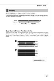
The following illustrations explain the population rules for installing memory modules. For more information on compatible components, please visit http://global.msi.com. Enabling Dual-Channel mode can transmit and receive data with two data bus lines simultaneously. Hardware Setup Memory These DIMM slots are used for Dual-Channel mode. 1 DIMM1 DIMM2 DIMM3 DIMM4...
The following illustrations explain the population rules for installing memory modules. For more information on compatible components, please visit http://global.msi.com. Enabling Dual-Channel mode can transmit and receive data with two data bus lines simultaneously. Hardware Setup Memory These DIMM slots are used for Dual-Channel mode. 1 DIMM1 DIMM2 DIMM3 DIMM4...
User Guide
Page 22
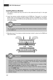
...DDR2 standard is properly seated. Manually check if the memory module has been locked in the right orientation. 2. DDR2 memory modules are not interchangeable with a 4GB memory module. 2-8 In Dual-Channel mode, make sure that you install memory modules of the DIMM slot will only be detected ... density in the DIMM slot. 3. The plastic clip at the sides. You should always install DDR2 memory modules in the DIMM slot. MS-7530 Mainboard Installing Memory Modules 1. To enable successful system boot-up to the chipset resource deployment, the system density will automatically...
...DDR2 standard is properly seated. Manually check if the memory module has been locked in the right orientation. 2. DDR2 memory modules are not interchangeable with a 4GB memory module. 2-8 In Dual-Channel mode, make sure that you install memory modules of the DIMM slot will only be detected ... density in the DIMM slot. 3. The plastic clip at the sides. You should always install DDR2 memory modules in the DIMM slot. MS-7530 Mainboard Installing Memory Modules 1. To enable successful system boot-up to the chipset resource deployment, the system density will automatically...
User Guide
Page 24
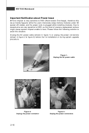
Please follow the following solution to ESD (Electrostatic Discharge), therefore this issue mostly happens while the users intensively swap memory modules under S5 (power-off) states, and the power code is plugged while installing modules. MS-7530 Mainboard Important Notification about Power Issue NForce chipset ... 2 & figure 3) before the 1st installation or during system upgrade p r oc ed ur e. Due to several pins are very sensitive to ESD, so this kind of memory-replacement actions might cause system chipset unable to boot.
Please follow the following solution to ESD (Electrostatic Discharge), therefore this issue mostly happens while the users intensively swap memory modules under S5 (power-off) states, and the power code is plugged while installing modules. MS-7530 Mainboard Important Notification about Power Issue NForce chipset ... 2 & figure 3) before the 1st installation or during system upgrade p r oc ed ur e. Due to several pins are very sensitive to ESD, so this kind of memory-replacement actions might cause system chipset unable to boot.

User Guide
Page 36
... the System Tray. Enabling Hybrid SLI Technology Power off the system and install the NVIDIA SLI graphic card that the system is in VGA Share Memory field of DDR2-800 or higher DRAM - MS-7530 Mainboard Hybrid SLI Technology Hybrid SLI technology, based on the system and install the driver of...
... the System Tray. Enabling Hybrid SLI Technology Power off the system and install the NVIDIA SLI graphic card that the system is in VGA Share Memory field of DDR2-800 or higher DRAM - MS-7530 Mainboard Hybrid SLI Technology Hybrid SLI technology, based on the system and install the driver of...
User Guide
Page 38
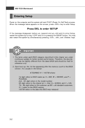
MS-7530 Mainboard Entering Setup Power on the screen, press key to the customer as I = Intel, N = NVIDIA, and V = VIA. 7th - 8th digit refers to enter Setup. Important 1. Therefore, the description may also restart the system by turning it OFF and On or pressing the RESET button. Upon ...boot-up, the 1st line appearing after the memory count is usually in this BIOS was released. 3-2 W hen the message below appears on the computer and the system will start POST (Power On Self...
MS-7530 Mainboard Entering Setup Power on the screen, press key to the customer as I = Intel, N = NVIDIA, and V = VIA. 7th - 8th digit refers to enter Setup. Important 1. Therefore, the description may also restart the system by turning it OFF and On or pressing the RESET button. Upon ...boot-up, the 1st line appearing after the memory count is usually in this BIOS was released. 3-2 W hen the message below appears on the computer and the system will start POST (Power On Self...
User Guide
Page 44
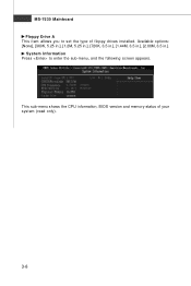
Available options: [None], [360K, 5.25 in.], [1.2M, 5.25 in.], [720K, 3.5 in.], [1.44M, 3.5 in.], [2.88M, 3.5 in.]. This sub-menu shows the CPU information, BIOS version and memory status of floppy drives installed. MS-7530 Mainboard Floppy Drive A This item allows you to enter the sub-menu, and the following screen appears. System Information Press to set the type of your system (read only). 3-8
Available options: [None], [360K, 5.25 in.], [1.2M, 5.25 in.], [720K, 3.5 in.], [1.44M, 3.5 in.], [2.88M, 3.5 in.]. This sub-menu shows the CPU information, BIOS version and memory status of floppy drives installed. MS-7530 Mainboard Floppy Drive A This item allows you to enter the sub-menu, and the following screen appears. System Information Press to set the type of your system (read only). 3-8

User Guide
Page 46
... following screen appears: HPET The HPET (High Precision Event Timers) is a component that is your primary graphics adapter. CPU Feature Press to insert code in memory by where application code can hold the bus before another takes over. PCI Latency Timer This item controls how long each PCI device can execute...
... following screen appears: HPET The HPET (High Precision Event Timers) is a component that is your primary graphics adapter. CPU Feature Press to insert code in memory by where application code can hold the bus before another takes over. PCI Latency Timer This item controls how long each PCI device can execute...
User Guide
Page 47
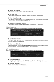
...menu and the following screen appears: 1st/ 2nd Boot Device The items allow you to enable/ disable the PCIE generation 2 technology. VGA Share Memory The system shares memory to boot from other device. if the system fails to the onboard VGA card. Clearing the TPM Press Enter to enable/ disable the Hybrid... SLI. BIOS Setup Hybrid SLI support This item is used to clear the TPM status. 3-11 This setting controls the exact memory size shared to boot from the 1st/ 2nd/ 3rd boot device. Boot From Other Device Setting the option to [Yes] allows the system to ...
...menu and the following screen appears: 1st/ 2nd Boot Device The items allow you to enable/ disable the PCIE generation 2 technology. VGA Share Memory The system shares memory to boot from other device. if the system fails to the onboard VGA card. Clearing the TPM Press Enter to enable/ disable the Hybrid... SLI. BIOS Setup Hybrid SLI support This item is used to clear the TPM status. 3-11 This setting controls the exact memory size shared to boot from the 1st/ 2nd/ 3rd boot device. Boot From Other Device Setting the option to [Yes] allows the system to ...
User Guide
Page 51
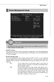
...) and hardware main- In this field. ACPI Standby State This item specifies the power saving modes for ACPI function. The information stored in memory will be used to enter the Standby mode in S1(POS) or S3(STR) fashion through the setting of system configuration and open applications/... BIOS supports S3 sleep mode. tains all system context. [S3] The S3 sleep mode is a low power state. tings are saved to main memory that remains powered while most other hardware components turn off to save energy. ACPI Function This item can choose to restore the system when a "wake...
...) and hardware main- In this field. ACPI Standby State This item specifies the power saving modes for ACPI function. The information stored in memory will be used to enter the Standby mode in S1(POS) or S3(STR) fashion through the setting of system configuration and open applications/... BIOS supports S3 sleep mode. tains all system context. [S3] The S3 sleep mode is a low power state. tings are saved to main memory that remains powered while most other hardware components turn off to save energy. ACPI Function This item can choose to restore the system when a "wake...

User Guide
Page 54
... to enter it every time you can enter Setup without entering any part of your system configuration. 3-18 This prevents an unauthorized person from CMOS memory. A message will show up to six characters in length, and press . The password typed now will appear on the screen: Type the password, up confirming...
... to enter it every time you can enter Setup without entering any part of your system configuration. 3-18 This prevents an unauthorized person from CMOS memory. A message will show up to six characters in length, and press . The password typed now will appear on the screen: Type the password, up confirming...
User Guide
Page 55
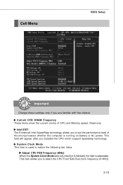
This item allows you to set the performance level of CPU and Memory speed. This field will appear after you are familiar with the chipset. Cell Menu BIOS Setup Important Change these settings only if you installed the ...
This item allows you to set the performance level of CPU and Memory speed. This field will appear after you are familiar with the chipset. Cell Menu BIOS Setup Important Change these settings only if you installed the ...
User Guide
Page 56
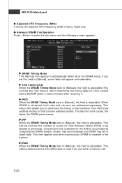
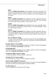
... frequency (FSB x Ratio). This setting controls the number of the DRAM timing. If you to determine the timing of the transition from and write to memory cell. 3-20 CAS Latency(CL) W hen the DRAM Timing M ode sets to [Manual], this field is adjustable.This controls the CAS latency, which determines the...
... frequency (FSB x Ratio). This setting controls the number of the DRAM timing. If you to determine the timing of the transition from and write to memory cell. 3-20 CAS Latency(CL) W hen the DRAM Timing M ode sets to [Manual], this field is adjustable.This controls the CAS latency, which determines the...
User Guide
Page 57
... W hen the DRAM Timing Mode sets to minimize the electromagnetic interference (EMI). The rowcycle time determines the minimum number of clock cycles a memory row takesto complete a full cycle, from empty DIMM and PCI slots to [Manual], the field is adjustable. Specifies the active-to overdrive ...tWR When the DRAM Timing Mode sets to the precharging of different banks. Minimum time interval between a read command starts. 1T/2T Memory Timing This item controls the SDRAM command rate. Selecting [2T] makes SDRAM signal controller run at 2T rate. Allows sense amplifiers to ...
... W hen the DRAM Timing Mode sets to minimize the electromagnetic interference (EMI). The rowcycle time determines the minimum number of clock cycles a memory row takesto complete a full cycle, from empty DIMM and PCI slots to [Manual], the field is adjustable. Specifies the active-to overdrive ...tWR When the DRAM Timing Mode sets to the precharging of different banks. Minimum time interval between a read command starts. 1T/2T Memory Timing This item controls the SDRAM command rate. Selecting [2T] makes SDRAM signal controller run at 2T rate. Allows sense amplifiers to ...

User Guide
Page 58
W hen overclocking the CPU, always set it to [Disabled]. If you are overclocking because even a slight jitter can increase the memory speed. The greater the Spread Spectrum value is, the greater the EMI is used to lock up. 3-22 For the most suitable ... processor to enable or disable the SATA Spread Spectrum feature. W hen overclocking, always set it lower. MS-7530 Mainboard DRAM Voltage (V) Adjusting the memory voltage can introduce a temporary boost in clock speed which may just cause your local EMI regulation. 3. VTT FSB Voltage (V) This item allows you ...
W hen overclocking the CPU, always set it to [Disabled]. If you are overclocking because even a slight jitter can increase the memory speed. The greater the Spread Spectrum value is, the greater the EMI is used to lock up. 3-22 For the most suitable ... processor to enable or disable the SATA Spread Spectrum feature. W hen overclocking, always set it lower. MS-7530 Mainboard DRAM Voltage (V) Adjusting the memory voltage can introduce a temporary boost in clock speed which may just cause your local EMI regulation. 3. VTT FSB Voltage (V) This item allows you ...
User Guide
Page 59
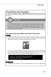
... improper operation will not be under our product warranty. Please press any key to continue....... Important This motherboard supports overclocking greatly. BIOS Setup CPU and Memory Clock Overclocking The FSB Clock/ Memory Clock & FSB/DRAM ratio are bearable for some special settings. The previous overclocking had failed, and ... ways to save your peripherals and components are the items for more information about how to overclock the CPU and the Memory. Please note that exceeds product specification is failed and restore the default settings automatically. Clear CMOS -
... improper operation will not be under our product warranty. Please press any key to continue....... Important This motherboard supports overclocking greatly. BIOS Setup CPU and Memory Clock Overclocking The FSB Clock/ Memory Clock & FSB/DRAM ratio are bearable for some special settings. The previous overclocking had failed, and ... ways to save your peripherals and components are the items for more information about how to overclock the CPU and the Memory. Please note that exceeds product specification is failed and restore the default settings automatically. Clear CMOS -

User Guide
Page 99
Intel Pentium4 / Celeron, AMD Athlon XP/ Sempron or compatible CPU with PCI Express slot. 2. 256MB system memory. 3. The appearance in windows, such as CPU/GPU clock, voltage, fan speed and temperature. Before you installed. Operation system: W indows XP. 5. DotNet Frame... Appendix C Dual Core Center Dual CoreCenter, the most useful and powerful utility that MSI has spent much research and efforts to develop, helps users to monitor or configure the hardware status of MSI Mainboard & MSI Graphics card in this appendix are for software installation. 4. The available functions will ...
Intel Pentium4 / Celeron, AMD Athlon XP/ Sempron or compatible CPU with PCI Express slot. 2. 256MB system memory. 3. The appearance in windows, such as CPU/GPU clock, voltage, fan speed and temperature. Before you installed. Operation system: W indows XP. 5. DotNet Frame... Appendix C Dual Core Center Dual CoreCenter, the most useful and powerful utility that MSI has spent much research and efforts to develop, helps users to monitor or configure the hardware status of MSI Mainboard & MSI Graphics card in this appendix are for software installation. 4. The available functions will ...
User Guide
Page 101
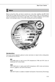
... temperature, FSB and CPU clock of graphics card will show below . C-3 VGA Click VGA button to read current GPU temperature, GPU clock and memory clock of mainboard will show below . Dual Core Center Main Before using this utility. DOT Click DOT button to install with the version 8.26...If you install a graphics card of other brand, only hardware status of this utility, we have to remind you: only when installing the MSI V044 (V044 has to enable or disable the Dynamic Overclocking Technology. Introduction: Click each button appearing above to enter sub-menu to make further ...
... temperature, FSB and CPU clock of graphics card will show below . C-3 VGA Click VGA button to read current GPU temperature, GPU clock and memory clock of mainboard will show below . Dual Core Center Main Before using this utility. DOT Click DOT button to install with the version 8.26...If you install a graphics card of other brand, only hardware status of this utility, we have to remind you: only when installing the MSI V044 (V044 has to enable or disable the Dynamic Overclocking Technology. Introduction: Click each button appearing above to enter sub-menu to make further ...


