
User Guide
Page 4
Notice 2 Shielded interface cables and A.C. Micro-Star International MS-7519 This device complies with the instructions, may cause harmful interference to radio communications. If this device must accept any , must be determined by turning ...
Notice 2 Shielded interface cables and A.C. Micro-Star International MS-7519 This device complies with the instructions, may cause harmful interference to radio communications. If this device must accept any , must be determined by turning ...

User Guide
Page 10
MS-7519 Mainboard Specifications Processor Support - Intel® next generation 45 nm Multi-core CPU *(For the latest information about CPU, please visit http://global.msi.com .tw/index.php?func=cpuform) Supported FSB - 1600* (OC)/ 1333/ 1066/ 800 MHz Chipset - Chip integrated by JMicron JMB381... En-2 Supports 1394 by Realtek® ALC888 - North Bridge: Intel® P45/ G45/ P43 chipset - Com pliant with jack sensing...
MS-7519 Mainboard Specifications Processor Support - Intel® next generation 45 nm Multi-core CPU *(For the latest information about CPU, please visit http://global.msi.com .tw/index.php?func=cpuform) Supported FSB - 1600* (OC)/ 1333/ 1066/ 800 MHz Chipset - Chip integrated by JMicron JMB381... En-2 Supports 1394 by Realtek® ALC888 - North Bridge: Intel® P45/ G45/ P43 chipset - Com pliant with jack sensing...

User Guide
Page 14
MS-7519 Mainboard CPU & Cooler Installation Procedures for demonstration of the mainboard. 11.Press the four hooks down the cooler until its four clips get wedged ...
MS-7519 Mainboard CPU & Cooler Installation Procedures for demonstration of the mainboard. 11.Press the four hooks down the cooler until its four clips get wedged ...

User Guide
Page 16
... is deeply inserted in place by the DIMM slot clips at i on. 2. Manually check if the memory m odule has been locked in the DIMM slot. MS-7519 Mainboard Installing Memory Modules You can barely see the golden finger if the memory module is properly inserted in the DIMM slot. 3. Important You...
... is deeply inserted in place by the DIMM slot clips at i on. 2. Manually check if the memory m odule has been locked in the DIMM slot. MS-7519 Mainboard Installing Memory Modules You can barely see the golden finger if the memory module is properly inserted in the DIMM slot. 3. Important You...
User Guide
Page 18
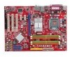
MS-7519 Mainboard Serial ATA Connector: SATA1~6 This connector is compliant with Intel® Front Panel I/O Connectivity Design Guide. Otherwise, data loss may occur during transmission. ...
MS-7519 Mainboard Serial ATA Connector: SATA1~6 This connector is compliant with Intel® Front Panel I/O Connectivity Design Guide. Otherwise, data loss may occur during transmission. ...
User Guide
Page 20
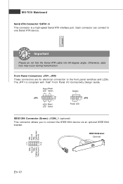
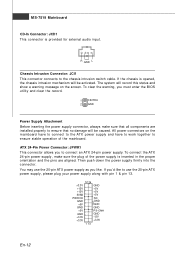
... supply connector, always make sure the plug of the m ainboard. To clear the warning, you 'd like . ATX 24-Pin Power Connector: JPWR1 This connector allows you like to use the 20-pin ATX power supply as you to ensure that all components are aligned. You may use the 20-pin...c on the screen. If the chassis is inserted in the proper orientation and the pins are installed properly to connect an ATX 24-pin power supply. The system will be caused. MS-7519 Mainboard CD-In Connector: JCD1 This connector is provided for external audio input. R GND L Chassis Intrusion Connector: JCI1...
... supply connector, always make sure the plug of the m ainboard. To clear the warning, you 'd like . ATX 24-Pin Power Connector: JPWR1 This connector allows you like to use the 20-pin ATX power supply as you to ensure that all components are aligned. You may use the 20-pin...c on the screen. If the chassis is inserted in the proper orientation and the pins are installed properly to connect an ATX 24-pin power supply. The system will be caused. MS-7519 Mainboard CD-In Connector: JCD1 This connector is provided for external audio input. R GND L Chassis Intrusion Connector: JCI1...

User Guide
Page 22
... return to keep the data of system configuration. W ith the CMOS RAM, the system can clear CMOS by shorting 2-3 pin while the system is off. MS-7519 Mainboard Clear CMOS Jumper: JBAT1 There is a CMOS RAM onboard that has a power supply from an external battery to 12 pin position. PCI Express...
... return to keep the data of system configuration. W ith the CMOS RAM, the system can clear CMOS by shorting 2-3 pin while the system is off. MS-7519 Mainboard Clear CMOS Jumper: JBAT1 There is a CMOS RAM onboard that has a power supply from an external battery to 12 pin position. PCI Express...

User Guide
Page 24
... selected. 100 Mbit/sec data rate is selected. 1000 Mbit/sec data rate is not established. Line-Out (Green) - Rear-Surround Out in 5.1/ 7.1 channel m ode. MS-7519 Mainboard 1394 Port The IEEE1394 port on the back panel provides connection to the Local Area Network (LAN).
... selected. 100 Mbit/sec data rate is selected. 1000 Mbit/sec data rate is not established. Line-Out (Green) - Rear-Surround Out in 5.1/ 7.1 channel m ode. MS-7519 Mainboard 1394 Port The IEEE1394 port on the back panel provides connection to the Local Area Network (LAN).

User Guide
Page 25
... refers to the model number. 6th refers to the Chipset vender as A = AMD, I = Intel, V = VIA, N = Nvidia, U = ULi. 7th - 8th digit refers to the customer as MS = all standard customers. English BIOS Setup This chapter provides basic information on the screen during the system booting up , the 1st line appearing after the...
... refers to the model number. 6th refers to the Chipset vender as A = AMD, I = Intel, V = VIA, N = Nvidia, U = ULi. 7th - 8th digit refers to the customer as MS = all standard customers. English BIOS Setup This chapter provides basic information on the screen during the system booting up , the 1st line appearing after the...
User Guide
Page 26
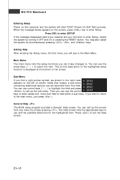
... m enu lists the setup functions you want to return to enter values and move from this screen from any menu by simultaneously pressing , , and keys. MS-7519 Mainboard Entering Setup Power on the computer and the system will see is displayed at the bottom of the screen. The Help screen lists...
... m enu lists the setup functions you want to return to enter values and move from this screen from any menu by simultaneously pressing , , and keys. MS-7519 Mainboard Entering Setup Power on the computer and the system will see is displayed at the bottom of the screen. The Help screen lists...

User Guide
Page 28
... press to enter the Standard CMOS Features-m enu. If you need the detailed settings of BIOS, please see the manual in English version on MSI website. En-20 MS-7519 Mainboard W hen enter the BIOS Setup utility, follow the processes below appears: Select [Ok] and press Enter to save the configurations and...
... press to enter the Standard CMOS Features-m enu. If you need the detailed settings of BIOS, please see the manual in English version on MSI website. En-20 MS-7519 Mainboard W hen enter the BIOS Setup utility, follow the processes below appears: Select [Ok] and press Enter to save the configurations and...


