
User Guide
Page 4
... can radiate radio frequency energy and, if not installed and used in order to comply with the instructions, may cause undesired operation. Micro-Star International MS-7519 This device complies with the limits for compliance could void the user's authority to radio or television reception, which the receiver is subject to...
... can radiate radio frequency energy and, if not installed and used in order to comply with the instructions, may cause undesired operation. Micro-Star International MS-7519 This device complies with the limits for compliance could void the user's authority to radio or television reception, which the receiver is subject to...

User Guide
Page 10
...1 IDE port by Realtek® ALC888 - Supports 1394 by Realtek 8111C Audio - North Bridge: Intel® P45/ G45/ P43 chipset - Supports PCIE LAN 10/100/1000 Fast Ethernet by JMicron JMB381 En-2 Supports PIO, Bus Master operation mode SATA - ... - Intel® next generation 45 nm Multi-core CPU *(For the latest information about CPU, please visit http://global.msi.com .tw/index.php?func=cpuform) Supported FSB - 1600* (OC)/ 1333/ 1066/ 800 MHz Chipset - Supports ... - Intel® Core 2 Extreme, Core 2 Quad, Core 2 Duo, Pentium Dual- MS-7519 Mainboard Specifications Processor Support -
...1 IDE port by Realtek® ALC888 - Supports 1394 by Realtek 8111C Audio - North Bridge: Intel® P45/ G45/ P43 chipset - Supports PCIE LAN 10/100/1000 Fast Ethernet by JMicron JMB381 En-2 Supports PIO, Bus Master operation mode SATA - ... - Intel® next generation 45 nm Multi-core CPU *(For the latest information about CPU, please visit http://global.msi.com .tw/index.php?func=cpuform) Supported FSB - 1600* (OC)/ 1333/ 1066/ 800 MHz Chipset - Supports ... - Intel® Core 2 Extreme, Core 2 Quad, Core 2 Duo, Pentium Dual- MS-7519 Mainboard Specifications Processor Support -

User Guide
Page 14
MS-7519 Mainboard CPU & Cooler Installation Procedures for correct mating, put down the CPU in the socket housing frame. Lift the load lever up and open ...
MS-7519 Mainboard CPU & Cooler Installation Procedures for correct mating, put down the CPU in the socket housing frame. Lift the load lever up and open ...

User Guide
Page 16
... been locked in place by the DIMM slot clips at i on the memory module is properly inserted in the right ori ent at the sides. MS-7519 Mainboard Installing Memory Modules You can barely see the golden finger if the memory module is deeply inserted in until the golden finger on...
... been locked in place by the DIMM slot clips at i on the memory module is properly inserted in the right ori ent at the sides. MS-7519 Mainboard Installing Memory Modules You can barely see the golden finger if the memory module is deeply inserted in until the golden finger on...
User Guide
Page 18
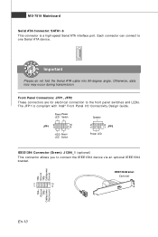
... LED Switch 2 1 8 7 JFP2 Power LED IEEE1394 Connector (Green): J1394_1 (optional) This connector allows you to connect the IEEE1394 device via an optional IEEE1394 brac ket . MS-7519 Mainboard Serial ATA Connector: SATA1~6 This connector is compliant with Intel® Front Panel I/O Connectivity Design Guide. Otherwise, data loss may occur during transmission...
... LED Switch 2 1 8 7 JFP2 Power LED IEEE1394 Connector (Green): J1394_1 (optional) This connector allows you to connect the IEEE1394 device via an optional IEEE1394 brac ket . MS-7519 Mainboard Serial ATA Connector: SATA1~6 This connector is compliant with Intel® Front Panel I/O Connectivity Design Guide. Otherwise, data loss may occur during transmission...
User Guide
Page 20
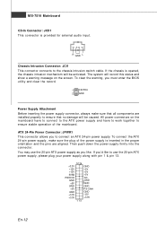
... To clear the warning, you to the chassis intrusion switch cable. Then push down the power supply firmly into the c on nec t or . ATX 24-Pin Power Connector: JPWR1 This connector allows you must enter the BIOS utility and clear the record. 1 CINTRU 2 GND Power Supply Attachment Before ... are aligned. If the chassis is provided for external audio input. R GND L Chassis Intrusion Connector: JCI1 This connector connects to connect an ATX 24-pin power supply. MS-7519 Mainboard CD-In Connector: JCD1 This connector is opened, the chassis intrusion mechanism will be caused.
... To clear the warning, you to the chassis intrusion switch cable. Then push down the power supply firmly into the c on nec t or . ATX 24-Pin Power Connector: JPWR1 This connector allows you must enter the BIOS utility and clear the record. 1 CINTRU 2 GND Power Supply Attachment Before ... are aligned. If the chassis is provided for external audio input. R GND L Chassis Intrusion Connector: JCI1 This connector connects to connect an ATX 24-pin power supply. MS-7519 Mainboard CD-In Connector: JCD1 This connector is opened, the chassis intrusion mechanism will be caused.

User Guide
Page 22
... the expansion card to 12 pin position. PCI Express Slot (x16/ x1) The PCI Express slot supports the PCI Express interface expansion card. En-14 MS-7519 Mainboard Clear CMOS Jumper: JBAT1 There is turned on. W ith the CMOS RAM, the system can clear CMOS by shorting 2-3 pin while the system...
... the expansion card to 12 pin position. PCI Express Slot (x16/ x1) The PCI Express slot supports the PCI Express interface expansion card. En-14 MS-7519 Mainboard Clear CMOS Jumper: JBAT1 There is turned on. W ith the CMOS RAM, the system can clear CMOS by shorting 2-3 pin while the system...

User Guide
Page 24
... rate is selected. 100 Mbit/sec data rate is selected. 1000 Mbit/sec data rate is used for different audio sound effects. CS-Out (Orange) - MS-7519 Mainboard 1394 Port The IEEE1394 port on the back panel provides connection to the Local Area Network (LAN).
... rate is selected. 100 Mbit/sec data rate is selected. 1000 Mbit/sec data rate is used for different audio sound effects. CS-Out (Orange) - MS-7519 Mainboard 1394 Port The IEEE1394 port on the back panel provides connection to the Local Area Network (LAN).

User Guide
Page 25
... , and requests you to run the Setup program when: * An error message appears on the BIOS Setup program and allows you to the customer as MS = all standard customers. En-17 V1.0 refers to the BIOS version. 051508 refers to the date this chapter are under each BIOS category described in...
... , and requests you to run the Setup program when: * An error message appears on the BIOS Setup program and allows you to the customer as MS = all standard customers. En-17 V1.0 refers to the BIOS version. 051508 refers to the date this chapter are under each BIOS category described in...
User Guide
Page 26
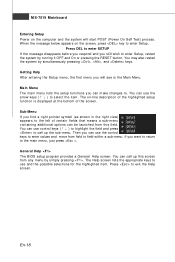
... by simultaneously pressing , , and keys. Press to select the item . W hen the m essage below appears on the screen, press key to field within a sub-menu. MS-7519 Mainboard Entering Setup Power on the computer and the system will see is displayed at the bottom of the screen. Main Menu The main...
... by simultaneously pressing , , and keys. Press to select the item . W hen the m essage below appears on the screen, press key to field within a sub-menu. MS-7519 Mainboard Entering Setup Power on the computer and the system will see is displayed at the bottom of the screen. Main Menu The main...

User Guide
Page 28
MS-7519 Mainboard W hen enter the BIOS Setup utility, follow the processes below for general use . 1. Important The configuration above are for general use only. En-... to load the default settings for optimal system performance. 2. If you need the detailed settings of BIOS, please see the manual in English version on MSI website. Adjust the Date, Tim e fields. 3. Load Optimized Defaults : Use control keys (↑↓ ) to highlight the Load Optimized Defaults field and press , a message as...
MS-7519 Mainboard W hen enter the BIOS Setup utility, follow the processes below for general use . 1. Important The configuration above are for general use only. En-... to load the default settings for optimal system performance. 2. If you need the detailed settings of BIOS, please see the manual in English version on MSI website. Adjust the Date, Tim e fields. 3. Load Optimized Defaults : Use control keys (↑↓ ) to highlight the Load Optimized Defaults field and press , a message as...


