User Guide
Page 2
...improvement and we reserve the right to the correctness of its contents. Alternatively, please try the following help resources for P35 Date June 2007 Technical Support If a problem arises with your place of International Business Machines Corporation. Our products are registered.../Vista are registered trademarks of Microsoft Corporation. Netware® is a registered trademark of Phoenix Technologies Ltd. Visit the MSI website for FAQ, technical guide, BIOS updates, driver updates, and other countries. AMI® is a registered trademark of M ICRO-STAR INTERNATIONAL. Copyright ...
...improvement and we reserve the right to the correctness of its contents. Alternatively, please try the following help resources for P35 Date June 2007 Technical Support If a problem arises with your place of International Business Machines Corporation. Our products are registered.../Vista are registered trademarks of Microsoft Corporation. Netware® is a registered trademark of Phoenix Technologies Ltd. Visit the MSI website for FAQ, technical guide, BIOS updates, driver updates, and other countries. AMI® is a registered trademark of M ICRO-STAR INTERNATIONAL. Copyright ...
User Guide
Page 8
...11 Connectors ...2-13 Jumper ...2-20 Button ...2-21 Slots ...2-22 LED Status Indicators 2-24 Chapter 3 BIOS Setup 3-1 Entering Setup ...3-2 The Main Menu ...3-4 Standard CMOS Features 3-6 Advanced BIOS Features 3-9 Integrated Peripherals 3-12 Power Management Setup 3-14 PNP/PCI Configurations 3-17 H/W Monitor ...3-19... Cell Menu ...3-20 Load Fail-Safe/ Optimized Defaults 3-26 BIOS Setting Password 3-27 Realtek ALC888/888T Audio Appendix A A-1 Installing the Realtek HD Audio Driver A-2 Software Configuration A-4 Hardware...
...11 Connectors ...2-13 Jumper ...2-20 Button ...2-21 Slots ...2-22 LED Status Indicators 2-24 Chapter 3 BIOS Setup 3-1 Entering Setup ...3-2 The Main Menu ...3-4 Standard CMOS Features 3-6 Advanced BIOS Features 3-9 Integrated Peripherals 3-12 Power Management Setup 3-14 PNP/PCI Configurations 3-17 H/W Monitor ...3-19... Cell Menu ...3-20 Load Fail-Safe/ Optimized Defaults 3-26 BIOS Setting Password 3-27 Realtek ALC888/888T Audio Appendix A A-1 Installing the Realtek HD Audio Driver A-2 Software Configuration A-4 Hardware...
User Guide
Page 9
Appendix B Dual Core Center B-1 Activating Dual Core Center B-2 Main ...B-2 DOT (Dynamic OverClocking B-5 Clock ...B-6 Voltage ...B-7 FAN Speed ...B-8 Temperature ...B-9 User Profile ...B-10 Appendix C Intel ICH9R SATA RAID C-1 ICH9R Introduction C-2 BIOS Configuration C-3 Installing Driver ...C-9 Installing Software C-11 RAID Migration Instructions C-15 Degraded RAID Array C-22 ix
Appendix B Dual Core Center B-1 Activating Dual Core Center B-2 Main ...B-2 DOT (Dynamic OverClocking B-5 Clock ...B-6 Voltage ...B-7 FAN Speed ...B-8 Temperature ...B-9 User Profile ...B-10 Appendix C Intel ICH9R SATA RAID C-1 ICH9R Introduction C-2 BIOS Configuration C-3 Installing Driver ...C-9 Installing Software C-11 RAID Migration Instructions C-15 Degraded RAID Array C-22 ix
User Guide
Page 20
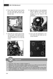
.... Press the four hooks down the load lever lightly onto the load plate, and then secure the lever with the plastic cap covered (shown in BIOS (Chapter 3). 2. Press down to lock the h ook s . 12. Read the CPU status in Figure 1) to confirm that the clip-ends are for demonstration of the...
.... Press the four hooks down the load lever lightly onto the load plate, and then secure the lever with the plastic cap covered (shown in BIOS (Chapter 3). 2. Press down to lock the h ook s . 12. Read the CPU status in Figure 1) to confirm that the clip-ends are for demonstration of the...
User Guide
Page 29
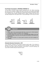
Fan cooler set with speed sensor to GND. CPUFAN supports fan control. To clear the warning, you must enter the BIOS utility and clear the record. If the mainboard has a System Hardware Monitor chipset on the screen. CINTRU 1 GND 2 JCI1 2-15 the black wire is Ground ...
Fan cooler set with speed sensor to GND. CPUFAN supports fan control. To clear the warning, you must enter the BIOS utility and clear the record. If the mainboard has a System Hardware Monitor chipset on the screen. CINTRU 1 GND 2 JCI1 2-15 the black wire is Ground ...

User Guide
Page 36
... Express interface expansion card. The PCI Express x 16 slot supports up to 4.0 GB/s transfer rate. You could select the speed of the PCI_E4 slot in BIOS setup. The PCI Express x 1 slot supports up to 250 MB/s transfer rate. Please refer to 1.0 GB/s transfer rate. Cell Menu - PCI_E1 PCI_E2 PCI_E3 PCI_E4 (Yellow... The PCI_E2 and the PCI_E3 slots share 4 PCIE channels with the PCI_E4 slot. PCIEx4 Speed Controller. 2-22 The PCI Express x 4 slot supports up to Chapter 3 BIOS Setup -
... Express interface expansion card. The PCI Express x 16 slot supports up to 4.0 GB/s transfer rate. You could select the speed of the PCI_E4 slot in BIOS setup. The PCI Express x 1 slot supports up to 250 MB/s transfer rate. Please refer to 1.0 GB/s transfer rate. Cell Menu - PCI_E1 PCI_E2 PCI_E3 PCI_E4 (Yellow... The PCI_E2 and the PCI_E3 slots share 4 PCIE channels with the PCI_E4 slot. PCIEx4 Speed Controller. 2-22 The PCI Express x 4 slot supports up to Chapter 3 BIOS Setup -

User Guide
Page 37
PCI Interrupt Request Routing The IRQ, acronym of interrupt request line and pronounced I-R-Q, are typically connected to the PCI bus pins as jumpers, switches or BIOS configuration. The PCI IRQ pins are hardware lines over which devices can send interrupt signals to configure any necessary hardware or software settings for the ...
PCI Interrupt Request Routing The IRQ, acronym of interrupt request line and pronounced I-R-Q, are typically connected to the PCI bus pins as jumpers, switches or BIOS configuration. The PCI IRQ pins are hardware lines over which devices can send interrupt signals to configure any necessary hardware or software settings for the ...
User Guide
Page 39
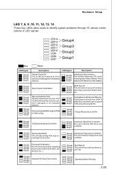
...booting. LED Signal Description Group4 Group3 Group2 Group1 Initializing Video Interface This will set low stack and boot via INT 19h. Decompressing BIOS image to identify system problems through 16 various combinations of LED signals. Group4 Group3 Group2 Group1 BootAttempt This will start detecting CPU... Group4 Group3 Group2 Group1 Group4 Group3 Group2 Group1 MemoryDetection Test Testing onboard memory size. Group4 Group3 Group2 Group1 BIOS Sign On This will start showing information about logo, processor brand name, etc... Group4 Group3 Group2 Group1 Testing VGA...
...booting. LED Signal Description Group4 Group3 Group2 Group1 Initializing Video Interface This will set low stack and boot via INT 19h. Decompressing BIOS image to identify system problems through 16 various combinations of LED signals. Group4 Group3 Group2 Group1 BootAttempt This will start detecting CPU... Group4 Group3 Group2 Group1 Group4 Group3 Group2 Group1 MemoryDetection Test Testing onboard memory size. Group4 Group3 Group2 Group1 BIOS Sign On This will start showing information about logo, processor brand name, etc... Group4 Group3 Group2 Group1 Testing VGA...

User Guide
Page 40
You may need to run the Setup program when: ² An error message appears on the BIOS Setup program and allows you to run SETUP. ² You want to configure the system for customized features. 3-1 Chapter 3 BIOS Setup BIOS Setup This chapter provides information on the screen during the system booting up, and requests you to change the default settings for optimum use.
You may need to run the Setup program when: ² An error message appears on the BIOS Setup program and allows you to run SETUP. ² You want to configure the system for customized features. 3-1 Chapter 3 BIOS Setup BIOS Setup This chapter provides information on the screen during the system booting up, and requests you to change the default settings for optimum use.

User Guide
Page 41
... it OFF and On or pressing the RESET button. V1.1 refers to the BIOS version. 030807 refers to the date this chapter are under each BIOS category described in the format: A7345IMS V1.0 030807 where: 1st digit refers to BIOS maker as A = AMI, W = AWARD, and P = PHOENIX. 2nd - 5th digit refers to.... 2. W hen the message below appears on the computer and the system will start POST (Power On Self Test) process. Important 1. It is the BIOS version. MS-7338 Mainboard Entering Setup Power on the screen, press key to enter Setup. Upon boot-up, the 1st line appearing after the memory...
... it OFF and On or pressing the RESET button. V1.1 refers to the BIOS version. 030807 refers to the date this chapter are under each BIOS category described in the format: A7345IMS V1.0 030807 where: 1st digit refers to BIOS maker as A = AMI, W = AWARD, and P = PHOENIX. 2nd - 5th digit refers to.... 2. W hen the message below appears on the computer and the system will start POST (Power On Self Test) process. Important 1. It is the BIOS version. MS-7338 Mainboard Entering Setup Power on the screen, press key to enter Setup. Upon boot-up, the 1st line appearing after the memory...
User Guide
Page 42
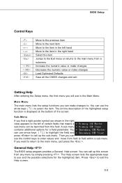
...-menu contains additional options for the highlighted item. The Help screen lists the appropriate keys to the main menu, just press the . General Help The BIOS setup program provides a General Help screen. Main Menu The main menu lists the setup functions you can be launched from this screen from any menu... by simply pressing . If you will see is displayed at the bottom of the screen. BIOS Setup Control Keys Enter> Move to the previous item Move to the next item Move to the item in the right hand Select the item...
...-menu contains additional options for the highlighted item. The Help screen lists the appropriate keys to the main menu, just press the . General Help The BIOS setup program provides a General Help screen. Main Menu The main menu lists the setup functions you can be launched from this screen from any menu... by simply pressing . If you will see is displayed at the bottom of the screen. BIOS Setup Control Keys Enter> Move to the previous item Move to the next item Move to the item in the right hand Select the item...
User Guide
Page 43
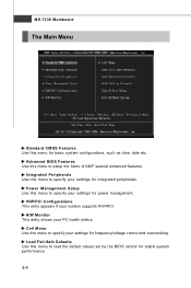
... this menu to specify your PC health status. Power Management Setup Use this menu to setup the items of AMI® special enhanced features. Advanced BIOS Features Use this menu to specify your settings for power management. Load Fail-Safe Defaults Use this menu for basic system configurations, such as time..., date etc. MS-7338 Mainboard The Main Menu Standard CMOS Features Use this menu to load the default values set by the BIOS vendor for stable system performance. 3-4
... this menu to specify your PC health status. Power Management Setup Use this menu to setup the items of AMI® special enhanced features. Advanced BIOS Features Use this menu to specify your settings for power management. Load Fail-Safe Defaults Use this menu for basic system configurations, such as time..., date etc. MS-7338 Mainboard The Main Menu Standard CMOS Features Use this menu to load the default values set by the BIOS vendor for stable system performance. 3-4

User Guide
Page 44
BIOS Setup Load Optimized Defaults Use this menu to set by the mainboard manufacturer specifically for BIOS. BIOS Setting Password Use this menu to CMOS and exit setup. Exit Without Saving Abandon all changes and exit setup. 3-5 Save & Exit Setup Save changes to load the default values set the password for optimal performance of the mainboard.
BIOS Setup Load Optimized Defaults Use this menu to set by the mainboard manufacturer specifically for BIOS. BIOS Setting Password Use this menu to CMOS and exit setup. Exit Without Saving Abandon all changes and exit setup. 3-5 Save & Exit Setup Save changes to load the default values set the password for optimal performance of the mainboard.
User Guide
Page 45
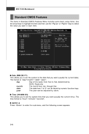
... by users. day Day of the week, from Sun to enter the sub-menu, and the following screen appears. 3-6 SATA1~6 Press to Sat, determined by BIOS. Date (MM:DD:YY) This allows you to set the system time that you want (usually the current date). Read-only. year The year can...
... by users. day Day of the week, from Sun to enter the sub-menu, and the following screen appears. 3-6 SATA1~6 Press to Sat, determined by BIOS. Date (MM:DD:YY) This allows you to set the system time that you want (usually the current date). Read-only. year The year can...
User Guide
Page 46
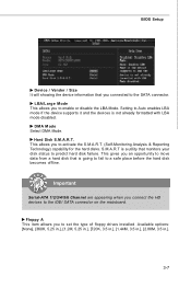
Hard Disk S.M.A.R.T. BIOS Setup Device / Vender / Size It will showing the device information that monitors your disk status to predict hard disk failure. DM A M ode Select DMA Mode. ...
Hard Disk S.M.A.R.T. BIOS Setup Device / Vender / Size It will showing the device information that monitors your disk status to predict hard disk failure. DM A M ode Select DMA Mode. ...
User Guide
Page 47
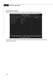
This sub-menu shows the CPU information, BIOS version and memory status of your system (read only). 3-8 MS-7338 Mainboard System Information Press to enter the sub-menu, and the following screen appears.
This sub-menu shows the CPU information, BIOS version and memory status of your system (read only). 3-8 MS-7338 Mainboard System Information Press to enter the sub-menu, and the following screen appears.

User Guide
Page 48
... the system is used to [Off] will expand available IRQ resources for the system. 3-9 Due to show the company logo on the bootup screen. Advanced BIOS Features BIOS Setup Full Screen LOGO Display This item enables you to compliance with PC2001 design guide, the system is powered on.
... the system is used to [Off] will expand available IRQ resources for the system. 3-9 Due to show the company logo on the bootup screen. Advanced BIOS Features BIOS Setup Full Screen LOGO Display This item enables you to compliance with PC2001 design guide, the system is powered on.

User Guide
Page 50
... [Yes] allows the system to try to boot from other device. if the system fails to boot from the 1st/ 2nd/ 3rd boot device. 3-11 BIOS Setup HPET The HPET (High Precision Event Timers) is a component that is part of the chipset. Boot Sequence Press to enter the sub-menu and... get to load the disk operating system. You can to enable it, and will provide you to set the first/ second/ third boot device where BIOS attempts to it via the various ACPI methods.
... [Yes] allows the system to try to boot from other device. if the system fails to boot from the 1st/ 2nd/ 3rd boot device. 3-11 BIOS Setup HPET The HPET (High Precision Event Timers) is a component that is part of the chipset. Boot Sequence Press to enter the sub-menu and... get to load the disk operating system. You can to enable it, and will provide you to set the first/ second/ third boot device where BIOS attempts to it via the various ACPI methods.
User Guide
Page 52
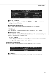
... allow users to select the type of IDE devices. RAID Mode This item is used PCI busmastering for SATA devices. BIOS Setup PCI IDE BusMaster This item allows you to enable/ disable BIOS to used to enable/disable the RAID function for reading/ writing to IDE drives. The submenu displays the status...
... allow users to select the type of IDE devices. RAID Mode This item is used PCI busmastering for SATA devices. BIOS Setup PCI IDE BusMaster This item allows you to enable/ disable BIOS to used to enable/disable the RAID function for reading/ writing to IDE drives. The submenu displays the status...
User Guide
Page 53
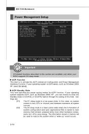
... chipset) and hardware maintains all system context. [S3] The S3 sleep mode is a lower power state where the in formation of this field. If your BIOS supports S3 sleep mode. ACPI Standby State This item specifies the power saving modes for ACPI function. ACPI Function This item is to restore the...
... chipset) and hardware maintains all system context. [S3] The S3 sleep mode is a lower power state where the in formation of this field. If your BIOS supports S3 sleep mode. ACPI Standby State This item specifies the power saving modes for ACPI function. ACPI Function This item is to restore the...


