
User Guide
Page 4
... turning the equipment off and on, the user is no guarantee that to provide reasonable protection against harmful interference in a particular installation. Micro-Star International MS-7392 This device complies with Part 15 of the measures listed below. † Reorient or relocate the receiving antenna. † Increase the separation between the equipment...
... turning the equipment off and on, the user is no guarantee that to provide reasonable protection against harmful interference in a particular installation. Micro-Star International MS-7392 This device complies with Part 15 of the measures listed below. † Reorient or relocate the receiving antenna. † Increase the separation between the equipment...

User Guide
Page 11
...Duo, Pentium Dual-core E2XXX and Celeron 4XX in the LGA775 package (For the latest information about CPU, please visit http://global.msi. ms i. Supports Ultra DMA 66/100, PIO & Bus Master operation mode SATA - 4 SATA ports are controlled by Realtek RTL8111B/ RTL8111C...php?f u nc =c puf orm) Supported FSB - 1333/ 1066/ 800 MHz Chipset - Supports 7.1 channels audio out - North Bridge: Intel® P31 - South Bridge: Intel® ICH7 Memory Support - t w / inde x . MS-7392 Mainboard Mainboard Specifications Processor Support - t w / inde x . c om. f unc =t e s t r epor t ) LAN - c om...
...Duo, Pentium Dual-core E2XXX and Celeron 4XX in the LGA775 package (For the latest information about CPU, please visit http://global.msi. ms i. Supports Ultra DMA 66/100, PIO & Bus Master operation mode SATA - 4 SATA ports are controlled by Realtek RTL8111B/ RTL8111C...php?f u nc =c puf orm) Supported FSB - 1333/ 1066/ 800 MHz Chipset - Supports 7.1 channels audio out - North Bridge: Intel® P31 - South Bridge: Intel® ICH7 Memory Support - t w / inde x . MS-7392 Mainboard Mainboard Specifications Processor Support - t w / inde x . c om. f unc =t e s t r epor t ) LAN - c om...

User Guide
Page 13
MS-7392 Mainboard Mainboard Layout Top : mouse Bottom: keyboard COM port CPUFAN1 ATX1 USB ports Top: LAN Jack Bottom: USB ports T:Line-In M:Line-Out B:Mic T:RS-Out M:CS-Out B:SS-Out JPW1 JLPT1 SYSFAN2 Intel P31 DIMM1 DIMM2 DIMM3 DIMM4 LAN chip PCIE_1 I/O Chip PCIE_2 PCI1 Audio chip PCI2 PCI3 Intel ICH7 JBAT1 B ATT + SATA1 SATA2 JCI1 IDE1 SATA3 SATA4 JAUD1 CD_IN1 JSPD1 JUSB2 JUSB1 FDD1 JFP1 JFP2 P31 Neo Series (MS-7392 v1.X) ATX Mainboard 1-4 SYSFAN1
MS-7392 Mainboard Mainboard Layout Top : mouse Bottom: keyboard COM port CPUFAN1 ATX1 USB ports Top: LAN Jack Bottom: USB ports T:Line-In M:Line-Out B:Mic T:RS-Out M:CS-Out B:SS-Out JPW1 JLPT1 SYSFAN2 Intel P31 DIMM1 DIMM2 DIMM3 DIMM4 LAN chip PCIE_1 I/O Chip PCIE_2 PCI1 Audio chip PCI2 PCI3 Intel ICH7 JBAT1 B ATT + SATA1 SATA2 JCI1 IDE1 SATA3 SATA4 JAUD1 CD_IN1 JSPD1 JUSB2 JUSB1 FDD1 JFP1 JFP2 P31 Neo Series (MS-7392 v1.X) ATX Mainboard 1-4 SYSFAN1

User Guide
Page 18
... protect the socket pin. 2. The availability of the CPU land side cover depends on the top to prevent overheating. The pins of your CPU packing. 2-4 MS-7392 Mainboard CPU & Cooler Installation W hen you install the CPU, always cover it to protect the contact from lever hinge side (as the arrow shows). 3. Before...
... protect the socket pin. 2. The availability of the CPU land side cover depends on the top to prevent overheating. The pins of your CPU packing. 2-4 MS-7392 Mainboard CPU & Cooler Installation W hen you install the CPU, always cover it to protect the contact from lever hinge side (as the arrow shows). 3. Before...

User Guide
Page 20
... confirm that the clip-ends are for demonstration of your CPU socket pin with the plastic cap covered (shown in this section are correctly inserted. MS-7392 Mainboard 9.
... confirm that the clip-ends are for demonstration of your CPU socket pin with the plastic cap covered (shown in this section are correctly inserted. MS-7392 Mainboard 9.

User Guide
Page 22
... interchangeable with a 1GB memory module. 2-8 Due to 3+GB (not full 4GB) when each side of the same type and density in the DDR2 DIMM slots. - MS-7392 Mainboard Installing Memory Modules 1. You should always install DDR2 memory modules in different channel DIMM slots. - The memory module has only one notch on the...
... interchangeable with a 1GB memory module. 2-8 Due to 3+GB (not full 4GB) when each side of the same type and density in the DDR2 DIMM slots. - MS-7392 Mainboard Installing Memory Modules 1. You should always install DDR2 memory modules in different channel DIMM slots. - The memory module has only one notch on the...

User Guide
Page 24
MS-7392 Mainboard Back Panel Mouse LAN Line-In RS-Out Line-Out CS-Out Keyboard Serial Port USB Ports Mic SS-Out Mouse/Keyboard Connector The ...
MS-7392 Mainboard Back Panel Mouse LAN Line-In RS-Out Line-Out CS-Out Keyboard Serial Port USB Ports Mic SS-Out Mouse/Keyboard Connector The ...

User Guide
Page 26
Each connector can connect to a 2-pin chassis switch. CINTRU 1 GND 2 JCI1 2-12 MS-7392 Mainboard Serial ATA Connector: SATA1/ SATA2/ SATA3/ SATA4 This connector is opened, the switch will record this status and show a warning message on the screen. ...
Each connector can connect to a 2-pin chassis switch. CINTRU 1 GND 2 JCI1 2-12 MS-7392 Mainboard Serial ATA Connector: SATA1/ SATA2/ SATA3/ SATA4 This connector is opened, the switch will record this status and show a warning message on the screen. ...

User Guide
Page 28
... DESCRIPTION Microphone - Left channel Ground Microphone - Left channel Jack detection return from the High Definition Audio CODEC jack detection resistor network No control Analog Port - MS-7392 Mainboard Front Panel Audio Connector: JAUD1 This connector allows you to the analog header.
... DESCRIPTION Microphone - Left channel Ground Microphone - Left channel Jack detection return from the High Definition Audio CODEC jack detection resistor network No control Analog Port - MS-7392 Mainboard Front Panel Audio Connector: JAUD1 This connector allows you to the analog header.

User Guide
Page 30
The parallel port is used to an optional parallel port bracket. MS-7392 Mainboard S/PDIF-Out Connector: JSPD1 (Optional) This connector is a standard printer port that supports Enhanced Parallel Port (EPP) and Extended Capabilities Parallel Port (ECP) mode. ...
The parallel port is used to an optional parallel port bracket. MS-7392 Mainboard S/PDIF-Out Connector: JSPD1 (Optional) This connector is a standard printer port that supports Enhanced Parallel Port (EPP) and Extended Capabilities Parallel Port (ECP) mode. ...
User Guide
Page 32
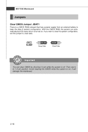
JBAT1 1 3 1 Keep Data 3 1 Clear Data Important You can automatically boot OS every time it will damage the mainboard. 2-18 W ith the CMOS RAM, the system can clear CMOS by shorting 2-3 pin while the system is on . Then return to clear data. If you want to clear the system configuration, set the jumper to 1-2 pin position. MS-7392 Mainboard Jumpers Clear CMOS Jumper: JBAT1 There is turned on ; Avoid clearing the CMOS while the system is off. it is a CMOS RAM onboard that has a power supply from an external battery to keep the data of system configuration.
JBAT1 1 3 1 Keep Data 3 1 Clear Data Important You can automatically boot OS every time it will damage the mainboard. 2-18 W ith the CMOS RAM, the system can clear CMOS by shorting 2-3 pin while the system is on . Then return to clear data. If you want to clear the system configuration, set the jumper to 1-2 pin position. MS-7392 Mainboard Jumpers Clear CMOS Jumper: JBAT1 There is turned on ; Avoid clearing the CMOS while the system is off. it is a CMOS RAM onboard that has a power supply from an external battery to keep the data of system configuration.

User Guide
Page 35
... BIOS maker as A = AMI, W = AWARD, and P = PHOENIX. 2nd - 5th digit refers to the model number. 6th digit refers to the chipset as MS = all standard customers. Important 1. W hen the message below appears on the computer and the system will start POST (Power On Self Test) process. Upon boot...you still wish to enter Setup. Therefore, the description may also restart the system by turning it OFF and On or pressing the RESET button. MS-7392 Mainboard Entering Setup Power on the screen, press key to enter Setup, restart the system by simultaneously pressing , , and keys. You may be...
... BIOS maker as A = AMI, W = AWARD, and P = PHOENIX. 2nd - 5th digit refers to the model number. 6th digit refers to the chipset as MS = all standard customers. Important 1. W hen the message below appears on the computer and the system will start POST (Power On Self Test) process. Upon boot...you still wish to enter Setup. Therefore, the description may also restart the system by turning it OFF and On or pressing the RESET button. MS-7392 Mainboard Entering Setup Power on the screen, press key to enter Setup, restart the system by simultaneously pressing , , and keys. You may be...

User Guide
Page 37
... the default values set by the BIOS vendor for integrated peripherals. Load Fail-Safe Defaults Use this menu to specify your settings for power management. MS-7392 Mainboard The Main Menu Standard CMOS Features Use this menu to setup the items of AMI® special enhanced features. Advanced BIOS Features Use this...
... the default values set by the BIOS vendor for integrated peripherals. Load Fail-Safe Defaults Use this menu to specify your settings for power management. MS-7392 Mainboard The Main Menu Standard CMOS Features Use this menu to setup the items of AMI® special enhanced features. Advanced BIOS Features Use this...

User Guide
Page 39
... screen appears. 3-6 Read-only. day Day of the week, from Jan. The format is . date The date from 1 to 31 can be keyed by users. MS-7392 Mainboard Standard CMOS Features The items in each item.
... screen appears. 3-6 Read-only. day Day of the week, from Jan. The format is . date The date from 1 to 31 can be keyed by users. MS-7392 Mainboard Standard CMOS Features The items in each item.

User Guide
Page 41
This sub-menu shows the CPU information, BIOS version and memory status of your system (read only). 3-8 MS-7392 Mainboard System Information Press to enter the sub-menu, and the following screen appears.
This sub-menu shows the CPU information, BIOS version and memory status of your system (read only). 3-8 MS-7392 Mainboard System Information Press to enter the sub-menu, and the following screen appears.

User Guide
Page 43
... of the processor to older operating systems. Hyper-Threading Technology The processor uses Hyper-Threading technology to insert code in memory by your operating system. MS-7392 Mainboard MPS Table Version This field allows you with a supporting operating system. CPU Feature Press to enter the sub-menu and the following screen appears...
... of the processor to older operating systems. Hyper-Threading Technology The processor uses Hyper-Threading technology to insert code in memory by your operating system. MS-7392 Mainboard MPS Table Version This field allows you with a supporting operating system. CPU Feature Press to enter the sub-menu and the following screen appears...
User Guide
Page 45
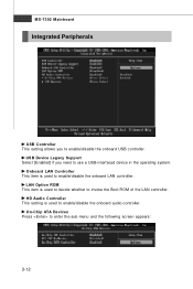
... and the following screen appears: 3-12 HD Audio Controller This setting is used to decide whether to invoke the Boot ROM of the LAN controller. MS-7392 Mainboard Integrated Peripherals USB Controller This setting allows you need to use a USB-interfaced device in the operating system.
... and the following screen appears: 3-12 HD Audio Controller This setting is used to decide whether to invoke the Boot ROM of the LAN controller. MS-7392 Mainboard Integrated Peripherals USB Controller This setting allows you need to use a USB-interfaced device in the operating system.

User Guide
Page 47
...) Function. The information stored in memory will be used to save energy. If your operating system supports ACPI, such as W indows 2000/ XP, select [Enabled]. MS-7392 Mainboard Power Management Setup Important S3-related functions described in this field. ACPI Function This item is a low power state. In this state, no system...
...) Function. The information stored in memory will be used to save energy. If your operating system supports ACPI, such as W indows 2000/ XP, select [Enabled]. MS-7392 Mainboard Power Management Setup Important S3-related functions described in this field. ACPI Function This item is a low power state. In this state, no system...
User Guide
Page 49
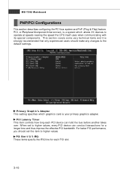
... and it is your primary graphics adapter. W hen set the item to higher values, every PCI device can hold the bus before another takes over. MS-7392 Mainboard PNP/PCI Configurations This section describes configuring the PCI bus system and PnP (Plug & Play) feature. PCI Latency Timer This item controls how long...
... and it is your primary graphics adapter. W hen set the item to higher values, every PCI device can hold the bus before another takes over. MS-7392 Mainboard PNP/PCI Configurations This section describes configuring the PCI bus system and PnP (Plug & Play) feature. PCI Latency Timer This item controls how long...
User Guide
Page 51
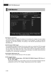
... select a fan target value here. CPU Min.FAN Speed (%) This field is once opened. It provides several sections to keep it with in a specific range. MS-7392 Mainboard H/W Monitor Chassis Intrusion The field enables or disables the feature of recording the chassis intrusion status and issuing a warning message if the chassis is...
... select a fan target value here. CPU Min.FAN Speed (%) This field is once opened. It provides several sections to keep it with in a specific range. MS-7392 Mainboard H/W Monitor Chassis Intrusion The field enables or disables the feature of recording the chassis intrusion status and issuing a warning message if the chassis is...


