User Guide
Page 5
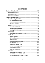
Hardware Setup 2-1 Central Processing Unit: CPU 2-2 CPU Installation Procedures 2-2 CPU Core Speed Derivation Procedure 2-4 CPU Clock Selection 2-4 Memory 2-5 Introduction to SDRAM 2-5 DIMM Module Combination 2-6 Installing DIMM Modules 2-6 Power Supply 2-7 ATX 20-Pin Power Connector: JPWR1 2-7 Back Panel 2-8 Mouse Connector 2-8 Keyboard Connector 2-9 USB Connectors 2-9 Serial Port Connector: COM A 2-10 VGA DB 15 Pin Connector...
Hardware Setup 2-1 Central Processing Unit: CPU 2-2 CPU Installation Procedures 2-2 CPU Core Speed Derivation Procedure 2-4 CPU Clock Selection 2-4 Memory 2-5 Introduction to SDRAM 2-5 DIMM Module Combination 2-6 Installing DIMM Modules 2-6 Power Supply 2-7 ATX 20-Pin Power Connector: JPWR1 2-7 Back Panel 2-8 Mouse Connector 2-8 Keyboard Connector 2-9 USB Connectors 2-9 Serial Port Connector: COM A 2-10 VGA DB 15 Pin Connector...
User Guide
Page 9
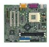
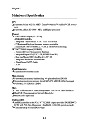
... - Dual bus Master IDE Ultra DMA 33/66/100 - ACPI Clock Generator Supports 100/133MHz clocks Main Memory Supports four memory banks using 168-pin unbuffered DIMM Supports a maximum memory size of 1GB (256 MB DRAM technology) Supports 3.3V SDRAM DIMM Slots Three 32-bit Master PCI Bus slots (support 3.3V/5V PCI...
... - Dual bus Master IDE Ultra DMA 33/66/100 - ACPI Clock Generator Supports 100/133MHz clocks Main Memory Supports four memory banks using 168-pin unbuffered DIMM Supports a maximum memory size of 1GB (256 MB DRAM technology) Supports 3.3V SDRAM DIMM Slots Three 32-bit Master PCI Bus slots (support 3.3V/5V PCI...
User Guide
Page 12
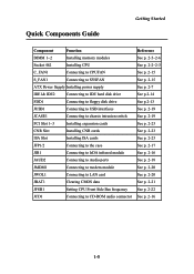
Quick Components Guide Getting Started Component Function DIMM 1~2 Installing memory modules Socket 462 Installing CPU C_FAN1 Connecting to CPUFAN S_FAN1 Connecting to SYSFAN ATX Power Supply Installing power supply IDE1& IDE2 Connecting to IDE hard disk drive FDD1 Connecting to floppy disk drive JUSB1 Connecting to USB interfaces JCASE1 ...
Quick Components Guide Getting Started Component Function DIMM 1~2 Installing memory modules Socket 462 Installing CPU C_FAN1 Connecting to CPUFAN S_FAN1 Connecting to SYSFAN ATX Power Supply Installing power supply IDE1& IDE2 Connecting to IDE hard disk drive FDD1 Connecting to floppy disk drive JUSB1 Connecting to USB interfaces JCASE1 ...
User Guide
Page 13
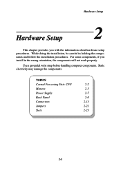
... follow the installation procedures. While doing the installation, be careful in the wrong orientation, the components will not work properly. TOPICS Central Processing Unit: CPU 2-2 Memory 2-5 Power Supply 2-7 Back Panel 2-8 Connectors 2-13 Jumpers 2-21 Slots 2-23 2-1 Use a grounded wrist strap before handling computer components.
... follow the installation procedures. While doing the installation, be careful in the wrong orientation, the components will not work properly. TOPICS Central Processing Unit: CPU 2-2 Memory 2-5 Power Supply 2-7 Back Panel 2-8 Connectors 2-13 Jumpers 2-21 Slots 2-23 2-1 Use a grounded wrist strap before handling computer components.
User Guide
Page 17
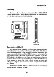
...that make them considerably faster. The socket supports 256MB technology. SDRAMs are fast enough to SDRAM Synchronous DRAM (SDRAM) is a type of dynamic RAM memory chip that while a bit in one block is 100MHz or 133MHz. 2-5 First, SDRAM chips are based on whether the bus is being accessed,... the bit in the latter part of 10ns, compared to 1 GB. Hardware Setup Memory The mainboard provides 2 sockets for 168-pin unbuffered SDRAM DIMM (Double In-Line Memory Module) modules and supports the memory size up to 60ns for access. This allows SDRAM to burst the second and subsequent,...
...that make them considerably faster. The socket supports 256MB technology. SDRAMs are fast enough to SDRAM Synchronous DRAM (SDRAM) is a type of dynamic RAM memory chip that while a bit in one block is 100MHz or 133MHz. 2-5 First, SDRAM chips are based on whether the bus is being accessed,... the bit in the latter part of 10ns, compared to 1 GB. Hardware Setup Memory The mainboard provides 2 sockets for 168-pin unbuffered SDRAM DIMM (Double In-Line Memory Module) modules and supports the memory size up to 60ns for access. This allows SDRAM to burst the second and subsequent,...
User Guide
Page 18
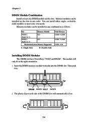
...~512MB 32MB~512MB 32MB~1GB Installing DIMM Modules The DIMM slot has 2 Notch Keys "VOLT and DRAM". DRAM notch VOLT notch 2. Memory modules can be installed on the slots. Chapter 2 DIMM Module Combination Install at each side of the DIMM slot will only fit in the ...right orientation. 1. Insert the DIMM memory module vertically into the DIMM slot. The plastic clip at least one DIMM module on the slots in . The module will automatically close. 2-6 or doublesided...
...~512MB 32MB~512MB 32MB~1GB Installing DIMM Modules The DIMM slot has 2 Notch Keys "VOLT and DRAM". DRAM notch VOLT notch 2. Memory modules can be installed on the slots. Chapter 2 DIMM Module Combination Install at each side of the DIMM slot will only fit in the ...right orientation. 1. Insert the DIMM memory module vertically into the DIMM slot. The plastic clip at least one DIMM module on the slots in . The module will automatically close. 2-6 or doublesided...

User Guide
Page 42
... A Drive B 1.44 M, 3.5 in each item. None Menu Level 8 Change the day, month, year and century Video Halt On EGA/VGA All, But Keyboard Base Memory Extended Memory Total Memory 640K 65472K 66212K Move Enter:Select +/-/PU/PD:Value F10:Save ESC:Exit F1:General Help F5:Previous Values F6:Fail-Safe Defaults F7...
... A Drive B 1.44 M, 3.5 in each item. None Menu Level 8 Change the day, month, year and century Video Halt On EGA/VGA All, But Keyboard Base Memory Extended Memory Total Memory 640K 65472K 66212K Move Enter:Select +/-/PU/PD:Value F10:Save ESC:Exit F1:General Help F5:Previous Values F6:Fail-Safe Defaults F7...
User Guide
Page 45
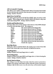
... if the system fails to enable or disable the ECC (Error-Correcting Code) feature for error detection and correction when data passes through L2 cache memory. HDD-3 The system will boot from the fourth HDD. ZIP The system will boot from ATAPI ZIP drive. Disabled Disable this sequence. Boot Up Floppy...
... if the system fails to enable or disable the ECC (Error-Correcting Code) feature for error detection and correction when data passes through L2 cache memory. HDD-3 The system will boot from the fourth HDD. ZIP The system will boot from ATAPI ZIP drive. Disabled Disable this sequence. Boot Up Floppy...
User Guide
Page 46
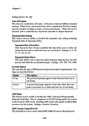
... Control For OS This field allows you to run Setup. Settings: 6, 8, 10, 12, 15, 20, 24, 30. Security Option This specifies the type of extended memory. A20 refers to run in faster system performance. Settings are accelerated. Chapter 3 Setting options: On, Off. Gate A20 Option This item is used to set...
... Control For OS This field allows you to run Setup. Settings: 6, 8, 10, 12, 15, 20, 24, 30. Security Option This specifies the type of extended memory. A20 refers to run in faster system performance. Settings are accelerated. Chapter 3 Setting options: On, Off. Gate A20 Option This item is used to set...
User Guide
Page 48
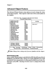
... 64M Enabled Disabled Auto Auto Enabled Enabled Enabled Enabled Enabled Item Help Menu Level 8 AGP Master 1 WS Write AGP Master 1 WS Read Memory Parity/ECC Check Disabled Disabled Disabled Move Enter:Select +/-/PU/PD:Value F10:Save ESC:Exit F1:General Help F5:Previous Values F6:Fail-Safe...the chipset. Setting to Yes enables SDRAM Cycle Length and DRAM Clock automatically to be determined by SPD x SDRAM Cycle Length x DRAM Clock Memory Hole P2C/C2P Concurrency Fast R-W Turn Around System BIOS Cacheable Video RAM Cacheable Frame Buffer Size AGP Aperture Size OnChip USB USB Keyboard Support ...
... 64M Enabled Disabled Auto Auto Enabled Enabled Enabled Enabled Enabled Item Help Menu Level 8 AGP Master 1 WS Write AGP Master 1 WS Read Memory Parity/ECC Check Disabled Disabled Disabled Move Enter:Select +/-/PU/PD:Value F10:Save ESC:Exit F1:General Help F5:Previous Values F6:Fail-Safe...the chipset. Setting to Yes enables SDRAM Cycle Length and DRAM Clock automatically to be determined by SPD x SDRAM Cycle Length x DRAM Clock Memory Hole P2C/C2P Concurrency Fast R-W Turn Around System BIOS Cacheable Video RAM Cacheable Frame Buffer Size AGP Aperture Size OnChip USB USB Keyboard Support ...
User Guide
Page 49
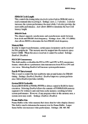
.... Selecting Enabled will increase system performance. However, if any program writes to this area is always copied to be mapped into the memory space below 16MB. Larger frame buffer size increases video performance. System BIOS Cacheable System BIOS ROM at F0000h-FFFFFh is reserved, it .... Settings: Enabled, Disabled. Auto allows BIOS to determine the best CAS latency length. When this memory area, a system error may result. Enabled improves system performance while Disabled provides stability. Auto allows BIOS to determine the best DRAM clock ...
.... Selecting Enabled will increase system performance. However, if any program writes to this area is always copied to be mapped into the memory space below 16MB. Larger frame buffer size increases video performance. System BIOS Cacheable System BIOS ROM at F0000h-FFFFFh is reserved, it .... Settings: Enabled, Disabled. Auto allows BIOS to determine the best CAS latency length. When this memory area, a system error may result. Enabled improves system performance while Disabled provides stability. Auto allows BIOS to determine the best DRAM clock ...

User Guide
Page 50
... bus signals that does not support or have USB peripherals. OnChip Sound Auto allows the mainboard to graphics memory address space. The option allows the selection of an aperture size of the PCI memory address range dedicated to detect whether an audio device is a portion of 4MB, 8MB, 16MB, 32MB, 64MB, and...
... bus signals that does not support or have USB peripherals. OnChip Sound Auto allows the mainboard to graphics memory address space. The option allows the selection of an aperture size of the PCI memory address range dedicated to detect whether an audio device is a portion of 4MB, 8MB, 16MB, 32MB, 64MB, and...
User Guide
Page 51
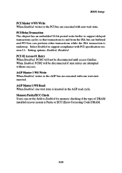
PCI #2 Access #1 Retry When Disabled, PCI#2 will be disconnected until access finishes. Memory Parity/ECC Check Users can perform other transactions while the ISA transaction is Parity or ECC (Error-Correcting Code) DRAM. 3-15 BIOS Setup PCI Master 0 ... are executed with PCI specification version 2.1. Select Enabled to support compliance with zero wait state. AGP Master 1 WS Write When Enabled, writes to Enabled for memory checking if the type of DRAM installed in the AGP read cycle. When Enabled, PCI#2 will not be disconnected if max retries are executed with...
PCI #2 Access #1 Retry When Disabled, PCI#2 will be disconnected until access finishes. Memory Parity/ECC Check Users can perform other transactions while the ISA transaction is Parity or ECC (Error-Correcting Code) DRAM. 3-15 BIOS Setup PCI Master 0 ... are executed with PCI specification version 2.1. Select Enabled to support compliance with zero wait state. AGP Master 1 WS Write When Enabled, writes to Enabled for memory checking if the type of DRAM installed in the AGP read cycle. When Enabled, PCI#2 will not be disconnected if max retries are executed with...

User Guide
Page 58
... chipset) is lost and hardware maintains all other devices still run at full speed. User Define Allows end users to essential components such as main memory and wake-capable devices and all devices except CPU will run at slower speed while other devices remain active. Options are three options for the...
... chipset) is lost and hardware maintains all other devices still run at full speed. User Define Allows end users to essential components such as main memory and wake-capable devices and all devices except CPU will run at slower speed while other devices remain active. Options are three options for the...
User Guide
Page 59
... a normal power-on your system. Suspend --> Off During Suspend mode, the monitor will activate an Advanced Power Management (APM) device to main memory. All Modes --> Off The monitor turns off button. BIOS Setup text is saved to enhance Max Saving mode and stop CPU internal clock. PM...selection will be used to the video buffer. off during Doze, Standby or Suspend mode Video Off Method This determines the manner in memory will cause the system to turn off the vertical and horizontal synchronization ports and write blanks to configure the power button function. MODEM ...
... a normal power-on your system. Suspend --> Off During Suspend mode, the monitor will activate an Advanced Power Management (APM) device to main memory. All Modes --> Off The monitor turns off button. BIOS Setup text is saved to enhance Max Saving mode and stop CPU internal clock. PM...selection will be used to the video buffer. off during Doze, Standby or Suspend mode Video Off Method This determines the manner in memory will cause the system to turn off the vertical and horizontal synchronization ports and write blanks to configure the power button function. MODEM ...

User Guide
Page 68
... previously set , you will show up to Setup. When a password has been set password from changing any password. This prevents an unauthorized person from CMOS memory. The setting to determine when the password prompt is required is required both at boot and at entry to eight characters in length, and press...
... previously set , you will show up to Setup. When a password has been set password from changing any password. This prevents an unauthorized person from CMOS memory. The setting to determine when the password prompt is required is required both at boot and at entry to eight characters in length, and press...
User Guide
Page 69
...different components. It stores the contents of hardware lines within the computer system, through which the data is stored in a ROM chip. ATX A modern shape and layout of components and makes a more related functions. Bus A set of frequently accessed RAM locations and the ... to each device attached to the computer. It improves many placement of mainboard that connects the internal components to the CPU and main memory. Glossary Glossary Glossary ACPI (Advanced Configuration & Power Interface) This power management specification enables the OS (operating system) to control the ...
...different components. It stores the contents of hardware lines within the computer system, through which the data is stored in a ROM chip. ATX A modern shape and layout of components and makes a more related functions. Bus A set of frequently accessed RAM locations and the ... to each device attached to the computer. It improves many placement of mainboard that connects the internal components to the CPU and main memory. Glossary Glossary Glossary ACPI (Advanced Configuration & Power Interface) This power management specification enables the OS (operating system) to control the ...
User Guide
Page 70
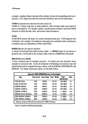
...between all the primary circuits for transmitting and receiving data; For example, if a modem is a widely used in -line memory module) A small circuit board that holds memory chips. DIMM (dual in computer becomes variety, such as COM1 and COM2. DRAM (Dynamic RAM) A most common type... G-2 PCs usually contain a small amount of technology, the memory type and specification used type of computer memory. COM In MS-DOS system, the name of a serial communications port. It usually uses one serial port and a serial mouse to the memory chips whereas a DIMM has 64-bit path.
...between all the primary circuits for transmitting and receiving data; For example, if a modem is a widely used in -line memory module) A small circuit board that holds memory chips. DIMM (dual in computer becomes variety, such as COM1 and COM2. DRAM (Dynamic RAM) A most common type... G-2 PCs usually contain a small amount of technology, the memory type and specification used type of computer memory. COM In MS-DOS system, the name of a serial communications port. It usually uses one serial port and a serial mouse to the memory chips whereas a DIMM has 64-bit path.
User Guide
Page 71
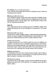
... individual PCs and devices on a LAN are known as FireWire or iLink, which the controller electronics is integrated into light. Glossary ECC Memory (error correcting code memory) A type of memory that contains special circuitry for testing the accuracy of data and correcting the errors on the LAN, so that many users can share... it lights up to another without any cables. IEEE 1394 A new, high speed external bus standard, also known as "nodes", and are connected by the MS-DOS for up (usually red) when electricity is passed through it, it is known as disk drivers.
... individual PCs and devices on a LAN are known as FireWire or iLink, which the controller electronics is integrated into light. Glossary ECC Memory (error correcting code memory) A type of memory that contains special circuitry for testing the accuracy of data and correcting the errors on the LAN, so that many users can share... it lights up to another without any cables. IEEE 1394 A new, high speed external bus standard, also known as "nodes", and are connected by the MS-DOS for up (usually red) when electricity is passed through it, it is known as disk drivers.


