User Guide
Page 1
... the equipment and receiver. 4 Connect the equipment into an outlet on , the user is connected. 4 Consult the dealer or an experienced radio/ television technician for help. power cord, if any interference received, including interference that interference will occur in a particular installation. This equipment generates, uses and can be used in accordance with the instruction manual, may not cause harmful...
... the equipment and receiver. 4 Connect the equipment into an outlet on , the user is connected. 4 Consult the dealer or an experienced radio/ television technician for help. power cord, if any interference received, including interference that interference will occur in a particular installation. This equipment generates, uses and can be used in accordance with the instruction manual, may not cause harmful...
User Guide
Page 2
...contents. Our products are registered trademarks of the Personal Computer Memory Card International Association. Trademarks All trademarks are registered trademarks of AMD Corporation. AMD, Athlon™ Athlon™XP, Thoroughbred™ and ...Award® is a registered trademark of Novell, Inc. We take every care in the preparation of this document is the intellectual property of MICRO-STAR INTERNATIONAL. Windows® 98/2000/NT/XP are registered trademarks of Phoenix Technologies Ltd. Copyright Notice The material in this document, but no guarantee is given as to make changes...
...contents. Our products are registered trademarks of the Personal Computer Memory Card International Association. Trademarks All trademarks are registered trademarks of AMD Corporation. AMD, Athlon™ Athlon™XP, Thoroughbred™ and ...Award® is a registered trademark of Novell, Inc. We take every care in the preparation of this document is the intellectual property of MICRO-STAR INTERNATIONAL. Windows® 98/2000/NT/XP are registered trademarks of Phoenix Technologies Ltd. Copyright Notice The material in this document, but no guarantee is given as to make changes...
User Guide
Page 3
... in an environment unconditioned, storage temperature above 60° C (140°F), it . The equipment does not work according to User Manual. - If any of explosion if battery is damaged. - The power cord or plug is incorrectly replaced. All cautions and warnings on card or module. 9. The .... 6. Always Unplug the Power Cord before connecting the equipment to moisture. - Safety Instructions 1. Always read the safety instructions carefully. 2. Place the power cord such a way that could damage or cause electrical shock. 11. Make sure the voltage of breakage. 12. Never...
... in an environment unconditioned, storage temperature above 60° C (140°F), it . The equipment does not work according to User Manual. - If any of explosion if battery is damaged. - The power cord or plug is incorrectly replaced. All cautions and warnings on card or module. 9. The .... 6. Always Unplug the Power Cord before connecting the equipment to moisture. - Safety Instructions 1. Always read the safety instructions carefully. 2. Place the power cord such a way that could damage or cause electrical shock. 11. Make sure the voltage of breakage. 12. Never...
User Guide
Page 7
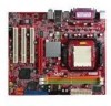
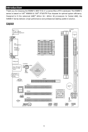
... CD_IN1 JUSB1 JUSB2 JFP2 JFP1 SATA1 SATA2 1 Introduction Thank you for Socket AM2, the K9MM-V Series delivers a high performance and professional desktop platform solution. Designed to fit the advanced AMD® Athlon 64 / Athlon X2 processors for choosing the K9MM-V (MS-7312 v1.x) series Micro-ATX mainboard. The K9MM-V series is based on VIA® K8M800 & VIA® VT8237R Plus chipsets for optimal system efficiency.
... CD_IN1 JUSB1 JUSB2 JFP2 JFP1 SATA1 SATA2 1 Introduction Thank you for Socket AM2, the K9MM-V Series delivers a high performance and professional desktop platform solution. Designed to fit the advanced AMD® Athlon 64 / Athlon X2 processors for choosing the K9MM-V (MS-7312 v1.x) series Micro-ATX mainboard. The K9MM-V series is based on VIA® K8M800 & VIA® VT8237R Plus chipsets for optimal system efficiency.
User Guide
Page 8
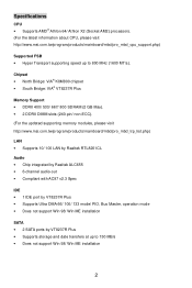
... the updated supporting memory modules, please visit http://www.msi.com.tw/program/products/mainboard/mbd/pro_mbd_trp_list.php) LAN • Supports 10/ 100 LAN by Realtek RTL8201CL Audio • Chip integrated by Realtek ALC655 • 6-channel audio-out • Compliant with AC97 v2.3 Spec IDE • 1 IDE port by VT8237R Plus • Supports Ultra DMA 66/ 100/ 133 mode/ PIO, Bus Master, operation mode • Does not support Win 98/ Win ME installation SATA • 2 SATA ports...
... the updated supporting memory modules, please visit http://www.msi.com.tw/program/products/mainboard/mbd/pro_mbd_trp_list.php) LAN • Supports 10/ 100 LAN by Realtek RTL8201CL Audio • Chip integrated by Realtek ALC655 • 6-channel audio-out • Compliant with AC97 v2.3 Spec IDE • 1 IDE port by VT8237R Plus • Supports Ultra DMA 66/ 100/ 133 mode/ PIO, Bus Master, operation mode • Does not support Win 98/ Win ME installation SATA • 2 SATA ports...
User Guide
Page 9
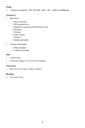
Floppy • 1 floppy port (supports 1 FDD with 360K, 720K, 1.2M, 1.44M and 2.88Mbytes) Connectors • Back Panel - 1 PS/2 mouse port - 1 PS/2 keyboard port - 1 Parallel port supporting SPP/EPP/ECP mode - 1 Serial port - 1 VGA port - 4 USB 2.0 ports - 1 LAN jack - 3 flexible audio jacks • On-Board Pinheaders - 2 USB pinheaders - 1 COM port pinheader Slots • 1 AGP 8X slot • 3 PCI slots, support 3.3V/ 5V PCI bus interface. Form Factor • Micro-ATX Form Factor: 245mm x 205mm Mounting • 6 mounting holes. 3
Floppy • 1 floppy port (supports 1 FDD with 360K, 720K, 1.2M, 1.44M and 2.88Mbytes) Connectors • Back Panel - 1 PS/2 mouse port - 1 PS/2 keyboard port - 1 Parallel port supporting SPP/EPP/ECP mode - 1 Serial port - 1 VGA port - 4 USB 2.0 ports - 1 LAN jack - 3 flexible audio jacks • On-Board Pinheaders - 2 USB pinheaders - 1 COM port pinheader Slots • 1 AGP 8X slot • 3 PCI slots, support 3.3V/ 5V PCI bus interface. Form Factor • Micro-ATX Form Factor: 245mm x 205mm Mounting • 6 mounting holes. 3
User Guide
Page 10
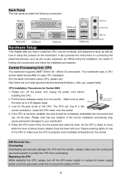
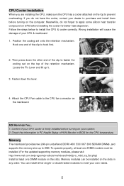
... panel provides the following connectors: Mouse Parallel port LAN port USB ports Line-in Line-out Mic-in Keyboard COM port VGA port USB ports Hardware Setup This chapter tells you how to install the CPU, memory modules, and expansion cards, as well as the mouse, keyboard, etc. The mainboard uses a CPU socket called Socket AM2 for easy CPU installation. (For the latest information about CPU, please visit: http://www.msi.com.tw/program/products/mainboard/mbd/pro_mbd_cpu_support.php) CPU Installation...
... panel provides the following connectors: Mouse Parallel port LAN port USB ports Line-in Line-out Mic-in Keyboard COM port VGA port USB ports Hardware Setup This chapter tells you how to install the CPU, memory modules, and expansion cards, as well as the mouse, keyboard, etc. The mainboard uses a CPU socket called Socket AM2 for easy CPU installation. (For the latest information about CPU, please visit: http://www.msi.com.tw/program/products/mainboard/mbd/pro_mbd_cpu_support.php) CPU Installation...
User Guide
Page 11
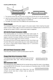
... on CPU before installing the cooler for the CPU temperature. Fasten down the other end of the clip to fasten the cooling set onto the retention mechanism. Attach the CPU Fan cable to install the CPU & cooler correctly. MSI Reminds You... 1. Memory The mainboard provides two 240-pin unbuffered DDRII 400/ 533/ 667/ 800 SDRAM DIMMs, and supports the memory size up it. 3. If you are installing the CPU...
... on CPU before installing the cooler for the CPU temperature. Fasten down the other end of the clip to fasten the cooling set onto the retention mechanism. Attach the CPU Fan cable to install the CPU & cooler correctly. MSI Reminds You... 1. Memory The mainboard provides two 240-pin unbuffered DDRII 400/ 533/ 667/ 800 SDRAM DIMMs, and supports the memory size up it. 3. If you are installing the CPU...
User Guide
Page 12
... 2 hard disk drives, CD-ROM, 120MB Floppy and other devices. There is suggested. You can connect a Master and a Slave drive. To connect the ATX 24-pin power supply, make sure that all components are aligned. Then push down the power supply firmly into the DIMM slot. IDE Connector: IDE1 The mainboard has a Ultra DMA 66/100/133 controller that supports 360K, 720K, 1.2M, 1.44M and 2.88M floppy disk types. You must configure second hard drive to the CPU. Installing...
... 2 hard disk drives, CD-ROM, 120MB Floppy and other devices. There is suggested. You can connect a Master and a Slave drive. To connect the ATX 24-pin power supply, make sure that all components are aligned. Then push down the power supply firmly into the DIMM slot. IDE Connector: IDE1 The mainboard has a Ultra DMA 66/100/133 controller that supports 360K, 720K, 1.2M, 1.44M and 2.88M floppy disk types. You must configure second hard drive to the CPU. Installing...
User Guide
Page 13
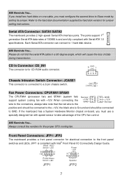
... be connected to a 2-pin chassis switch. Front Panel Connectors: JFP1/ JFP2 The mainboard provides a front panel connector for jumper setting instructions. If you install two hard disks on -board, you must use a specially designed fan with Serial ATA 1.0 specifications. MSI Reminds You... MSI Reminds You... Refer to 1 hard disk device. CD In Connector: CD_IN1 The connector is connected to GND. JFP1 is Ground and should be connected to the +12V, the black wire is compliant with +12V. GND 2 CINTRU 1 Fan Power Connectors: CPUFAN1...
... be connected to a 2-pin chassis switch. Front Panel Connectors: JFP1/ JFP2 The mainboard provides a front panel connector for jumper setting instructions. If you install two hard disks on -board, you must use a specially designed fan with Serial ATA 1.0 specifications. MSI Reminds You... MSI Reminds You... Refer to 1 hard disk device. CD In Connector: CD_IN1 The connector is connected to GND. JFP1 is Ground and should be connected to the +12V, the black wire is compliant with +12V. GND 2 CINTRU 1 Fan Power Connectors: CPUFAN1...
User Guide
Page 14
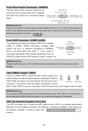
... be jumpered in the image to clear the data. Then return to directly access main memory. 8 AGP (Accelerated Graphics Port) Slot The AGP slot allows you want to connect to the front audio header, pins 5 & 6, 9 & 10 have signal output directed to the rear audio ports. Otherwise, the Line-Out connector on the back panel will damage the mainboard. which will not function. 2 10 1 9 Front USB Connector: JUSB1/JUSB2 The mainboard provides...
... be jumpered in the image to clear the data. Then return to directly access main memory. 8 AGP (Accelerated Graphics Port) Slot The AGP slot allows you want to connect to the front audio header, pins 5 & 6, 9 & 10 have signal output directed to the rear audio ports. Otherwise, the Line-Out connector on the back panel will damage the mainboard. which will not function. 2 10 1 9 Front USB Connector: JUSB1/JUSB2 The mainboard provides...
User Guide
Page 15
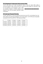
... hardware or software settings for the expansion card to make sure that you to insert the expansion cards to the PCI bus INT A# ~ INT D# pins as jumpers, switches or BIOS configuration. PCI Interrupt Request Routing The IRQ, abbreviation of interrupt request line and pronounced I-R-Q, are typically connected to meet your needs. Meanwhile, read the documentation for the expansion card, such as follows: PCI Slot 1 PCI Slot 2 PCI Slot 3 Order1 INT...
... hardware or software settings for the expansion card to make sure that you to insert the expansion cards to the PCI bus INT A# ~ INT D# pins as jumpers, switches or BIOS configuration. PCI Interrupt Request Routing The IRQ, abbreviation of interrupt request line and pronounced I-R-Q, are typically connected to meet your needs. Meanwhile, read the documentation for the expansion card, such as follows: PCI Slot 1 PCI Slot 2 PCI Slot 3 Order1 INT...
User Guide
Page 16
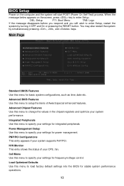
... supports PnP/PCI. Advanced Chipset Features Use this menu to load factory default settings into the BIOS for basic system configurations, such as time, date etc. DEL: Setup F11: Boot Menu TAB: Logo If the message disappears before you respond and you still wish to specify your settings for frequency/voltage control. BIOS Setup Power on the screen, press key to enter Setup. PNP/PCI Configurations This entry appears if your system performance. Main Page Standard CMOS Features Use...
... supports PnP/PCI. Advanced Chipset Features Use this menu to load factory default settings into the BIOS for basic system configurations, such as time, date etc. DEL: Setup F11: Boot Menu TAB: Logo If the message disappears before you respond and you still wish to specify your settings for frequency/voltage control. BIOS Setup Power on the screen, press key to enter Setup. PNP/PCI Configurations This entry appears if your system performance. Main Page Standard CMOS Features Use...
User Guide
Page 17
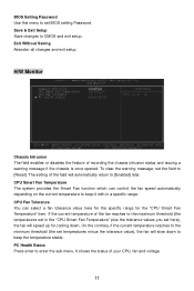
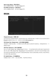
... Press enter to [Reset]. Save & Exit Setup Save changes to set temperatures minus the tolerance value), the fan will slow down . Exit Without Saving Abandon all changes and exit setup. If the current temperature of the field will speed up for the "CPU Smart Fan Temperature" item. H/W Monitor Chassis Intrusion The field enables or disables the feature of your CPU, fan and voltage. 11 BIOS Setting Password Use this menu to CMOS and exit setup. CPU Fan Tolerance You can control the fan speed...
... Press enter to [Reset]. Save & Exit Setup Save changes to set temperatures minus the tolerance value), the fan will slow down . Exit Without Saving Abandon all changes and exit setup. If the current temperature of the field will speed up for the "CPU Smart Fan Temperature" item. H/W Monitor Chassis Intrusion The field enables or disables the feature of your CPU, fan and voltage. 11 BIOS Setting Password Use this menu to CMOS and exit setup. CPU Fan Tolerance You can control the fan speed...
User Guide
Page 18
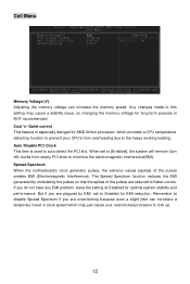
... changing the memory voltage for long-term purpose is NOT recommended. Spread Spectrum When the motherboard's clock generator pulses, the extreme values (spikes) of the pulses are overclocking because even a slight jitter can increase the memory speed. If you are reduced to auto detect the PCI slot. Cell Menu Memory Voltage (V) Adjusting the memory voltage can introduce a temporary boost in clock speed which provides a CPU temperature detecting function to prevent your overclocked processor...
... changing the memory voltage for long-term purpose is NOT recommended. Spread Spectrum When the motherboard's clock generator pulses, the extreme values (spikes) of the pulses are overclocking because even a slight jitter can increase the memory speed. If you are reduced to auto detect the PCI slot. Cell Menu Memory Voltage (V) Adjusting the memory voltage can introduce a temporary boost in clock speed which provides a CPU temperature detecting function to prevent your overclocked processor...
User Guide
Page 65
Exit Without Saving CMOS Setup 程序. 硬件监视 Chassis Intrusion Reset Enabled]状态. CPU Smart Fan Temperature(CPU CPU CPU Fan Tolerance(CPU CPU Smart Fan Temperature CPU Smart Fan Temperature CPU PC Health Status(PC Enter CPU 59 Save & Exit Setup CMOS Setup 程序.
Exit Without Saving CMOS Setup 程序. 硬件监视 Chassis Intrusion Reset Enabled]状态. CPU Smart Fan Temperature(CPU CPU CPU Fan Tolerance(CPU CPU Smart Fan Temperature CPU Smart Fan Temperature CPU PC Health Status(PC Enter CPU 59 Save & Exit Setup CMOS Setup 程序.
User Guide
Page 74
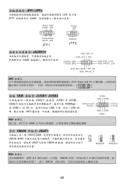
... 清除 CMOS 跨接器: JBAT1 CMOS RAM 3 CMOS RAM 2 1 JBAT1 (清除 CMOS 3 2 1 保K留ee資p D料ata 3 2 1 C清l e除a r資D料a t a MSI 2-3 CMOS 1-2 CMOS 68 JFP1/JFP2 LED JFP1 Intel Reset HDD Switch LED 9 1 10 2 PowerPower Switch LED JFP1 Power LED 7 1 8 2 Speaker JFP2 JAUDIO1 Intel AUD_RET_R AUD_VCC Key (2)AUD_GND (1)AUD_MIC AUD_RET_L(10) AUD_FPOUT_L(9) AUD_MIC_BIAS HP_ON AUD_FPOUT_R MSI 5 & 6, 9 & 10 2 10 1 9 面板 USB 連接...
... 清除 CMOS 跨接器: JBAT1 CMOS RAM 3 CMOS RAM 2 1 JBAT1 (清除 CMOS 3 2 1 保K留ee資p D料ata 3 2 1 C清l e除a r資D料a t a MSI 2-3 CMOS 1-2 CMOS 68 JFP1/JFP2 LED JFP1 Intel Reset HDD Switch LED 9 1 10 2 PowerPower Switch LED JFP1 Power LED 7 1 8 2 Speaker JFP2 JAUDIO1 Intel AUD_RET_R AUD_VCC Key (2)AUD_GND (1)AUD_MIC AUD_RET_L(10) AUD_FPOUT_L(9) AUD_MIC_BIAS HP_ON AUD_FPOUT_R MSI 5 & 6, 9 & 10 2 10 1 9 面板 USB 連接...
User Guide
Page 77
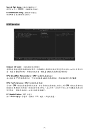
Save & Exit Setup CMOS Exit Without Saving H/W Monitor Chassis Intrusion Reset Enabled)。 CPU Smart Fan Temperature(CPU CPU Fan Tolerance(CPU CPU CPU PC Health Status( PC Enter CPU 71
Save & Exit Setup CMOS Exit Without Saving H/W Monitor Chassis Intrusion Reset Enabled)。 CPU Smart Fan Temperature(CPU CPU Fan Tolerance(CPU CPU CPU PC Health Status( PC Enter CPU 71

User Guide
Page 88
BIOS Setup POST (Power On Self Test DEL DEL: Setup F11: Boot Menu TAB: Logo
BIOS Setup POST (Power On Self Test DEL DEL: Setup F11: Boot Menu TAB: Logo
User Guide
Page 89
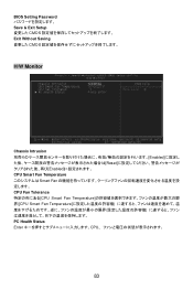
BIOS Setting Password Save & Exit Setup CMOS Exit Without Saving CMOS H/W Monitor Chassis Intrusion Enabled Reset Enabled CPU Smart Fan Temperature Smart Fan CPU Fan Tolerance CPU Smart Fan Temperature CPU Smart Fan Temperature PC Health Status Enter CPU 83
BIOS Setting Password Save & Exit Setup CMOS Exit Without Saving CMOS H/W Monitor Chassis Intrusion Enabled Reset Enabled CPU Smart Fan Temperature Smart Fan CPU Fan Tolerance CPU Smart Fan Temperature CPU Smart Fan Temperature PC Health Status Enter CPU 83


