User Guide
Page 2
... their respective owners. Visit the MSI website for FAQ, technical guide, BIOS updates, driver updates, and other countries. Trademarks All trademarks are registered trademarks or trademarks of NVIDIA Corporation in the United States and/or other information: http://www.msi.com.tw/program/service/faq/ faq/esc_faq_list.php Contact our technical staff at: http://support.msi.com.tw/ ii W indows...
... their respective owners. Visit the MSI website for FAQ, technical guide, BIOS updates, driver updates, and other countries. Trademarks All trademarks are registered trademarks or trademarks of NVIDIA Corporation in the United States and/or other information: http://www.msi.com.tw/program/service/faq/ faq/esc_faq_list.php Contact our technical staff at: http://support.msi.com.tw/ ii W indows...
User Guide
Page 3
... has not work according to the power inlet. 7. Keep this User's Manual for air convection hence protects the equip- fore connecting the equipment to User's Manual. † The equipment has dropped and damaged. † The equipment has obvious sign of the following situations arises, get it . Always Unplug the Power Cord before setting it up. 5. The openings on card or...
... has not work according to the power inlet. 7. Keep this User's Manual for air convection hence protects the equip- fore connecting the equipment to User's Manual. † The equipment has dropped and damaged. † The equipment has obvious sign of the following situations arises, get it . Always Unplug the Power Cord before setting it up. 5. The openings on card or...
User Guide
Page 4
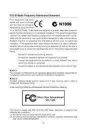
... may cause undesired operation. power cord, if any, must accept any interference received, including interference that interference will not occur in accordance with the emission limits. This equipment generates, uses and can be used in a particular installation. Micro-Star International MS-7280 This device complies with Part 15 of the FCC Rules. FCC-B Radio Frequency Interference Statement T h is...
... may cause undesired operation. power cord, if any, must accept any interference received, including interference that interference will not occur in accordance with the emission limits. This equipment generates, uses and can be used in a particular installation. Micro-Star International MS-7280 This device complies with Part 15 of the FCC Rules. FCC-B Radio Frequency Interference Statement T h is...
User Guide
Page 8
... Notice ...ii Tradema rks ...ii Revision History ...ii Technical Support ...ii Safety Instructions iii FCC-B Radio Frequency Interference Statement iv WEEE (Waste Electrical and Electronic Equipment) Statement v English ...En-1 Specifications ...En-1 How to use this Installation Guide En-3 Central Processing Unit: CPU En-4 Memory ...En-5 Connectors, Jumpers, Slots En-6 Back Panel ...En-12 BIOS Setup ...En-14 Software Information En-16 G e rm an ...De-1 Spezifikationen De...
... Notice ...ii Tradema rks ...ii Revision History ...ii Technical Support ...ii Safety Instructions iii FCC-B Radio Frequency Interference Statement iv WEEE (Waste Electrical and Electronic Equipment) Statement v English ...En-1 Specifications ...En-1 How to use this Installation Guide En-3 Central Processing Unit: CPU En-4 Memory ...En-5 Connectors, Jumpers, Slots En-6 Back Panel ...En-12 BIOS Setup ...En-14 Software Information En-16 G e rm an ...De-1 Spezifikationen De...
User Guide
Page 9
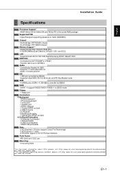
... t.php En-1 English Installation Guide Specifications Processor Support* - South Bridge: ATI® SB600 chipset Memory Support** - Controlled by RTL8111B & 8110SC IEEE 1394 - Azalis 1.0 Audio solution IDE - 1 IDE port controlled by Realtek ALC883 - SATA1~4 support RAID0/ RAID1/ RAID0+1 or JBOD mode Floppy - 1 floppy port Connectors Back panel - 1 PS/2 mouse port - 1 PS/2 keyboard port - 1 serial port - 1 parallel port - 1 IEEE 1394 port - 1 Coaxial SPDIF out jack - 4 USB 2.0 ports - 2 LAN jacks - 5 flexible audio jacks - 1 Optical fiber SPDIF out jack On-Board Pinheaders - 1 D-Bracket...
... t.php En-1 English Installation Guide Specifications Processor Support* - South Bridge: ATI® SB600 chipset Memory Support** - Controlled by RTL8111B & 8110SC IEEE 1394 - Azalis 1.0 Audio solution IDE - 1 IDE port controlled by Realtek ALC883 - SATA1~4 support RAID0/ RAID1/ RAID0+1 or JBOD mode Floppy - 1 floppy port Connectors Back panel - 1 PS/2 mouse port - 1 PS/2 keyboard port - 1 serial port - 1 parallel port - 1 IEEE 1394 port - 1 Coaxial SPDIF out jack - 4 USB 2.0 ports - 2 LAN jacks - 5 flexible audio jacks - 1 Optical fiber SPDIF out jack On-Board Pinheaders - 1 D-Bracket...
User Guide
Page 11
... Sockets : DIMM1~4 (dual channel) En-5 4 Fan Power Connectors 6 ATA 133 Hard Disk Connector 8 Front Panel Connectors En-6 En-6 En-7 5 Floppy Disk Driver Connector 7 Serial ATA 2.0 Connectors 9 Front USB 2.0 Connectors En-6 En-6 En-7 10 IEEE 1394 Connectors 14 CD-In Connector En-7 En-8 12 Front Panel Audio Connector 15 Chassis Intrusion Switch Connector En-8 En-8 16 IrDA Infrared Module Connector En-8 19 D-BracketTM 2 Connector En-9 20 Clear CMOS Jumper En-10 21 ATX 24-Pin Power Connector En-10 23 ATX 12V Power Connector (2x2-Pin) En-10 25 ATX 12V Power Connector (1x4-Pin...
... Sockets : DIMM1~4 (dual channel) En-5 4 Fan Power Connectors 6 ATA 133 Hard Disk Connector 8 Front Panel Connectors En-6 En-6 En-7 5 Floppy Disk Driver Connector 7 Serial ATA 2.0 Connectors 9 Front USB 2.0 Connectors En-6 En-6 En-7 10 IEEE 1394 Connectors 14 CD-In Connector En-7 En-8 12 Front Panel Audio Connector 15 Chassis Intrusion Switch Connector En-8 En-8 16 IrDA Infrared Module Connector En-8 19 D-BracketTM 2 Connector En-9 20 Clear CMOS Jumper En-10 21 ATX 24-Pin Power Connector En-10 23 ATX 12V Power Connector (2x2-Pin) En-10 25 ATX 12V Power Connector (1x4-Pin...
User Guide
Page 12
.... Locate the FixLever and lift up to purchase and install them before installing the CPU. 2. The gold arrow should be completely embedded into the socket and close the lever with your mainboard. 5. As the CPU is being closed, always close the lever. Look for Socket AM2 CPUs only. Replacing the CPU While replacing the CPU, always turn off theATX power supply or unplug the power supply's power cord...
.... Locate the FixLever and lift up to purchase and install them before installing the CPU. 2. The gold arrow should be completely embedded into the socket and close the lever with your mainboard. 5. As the CPU is being closed, always close the lever. Look for Socket AM2 CPUs only. Replacing the CPU While replacing the CPU, always turn off theATX power supply or unplug the power supply's power cord...
User Guide
Page 13
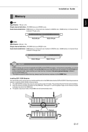
... dual-channel mode, make sure that you should always install DDRII memory module in the DDRII DIMM slot and install DDR memory module in Orange color. 64x2=128 pin 56x2=112 pin Important -DDRII modules are GREEN color. The plastic clip at each side of module. DIMM slot(s) on Channel A are marked in the DIMM slot. 3. English Installation Guide Memory 2 DDR Specification : 184-pin, 2.5v. To enable successful system boot...
... dual-channel mode, make sure that you should always install DDRII memory module in the DDRII DIMM slot and install DDR memory module in Orange color. 64x2=128 pin 56x2=112 pin Important -DDRII modules are GREEN color. The plastic clip at each side of module. DIMM slot(s) on Channel A are marked in the DIMM slot. 3. English Installation Guide Memory 2 DDR Specification : 184-pin, 2.5v. To enable successful system boot...
User Guide
Page 14
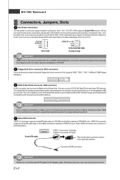
...and 2.88M floppy disk types. 6 ATA133 Hard Disk Connector (IDE connector) A IDE connector can connect a Master and a Slave drive. The CPU FAN supports Smart FAN function. When connect the wire to the connectors, always take advantage of 300 MB/s and will be connected to 1 hard disk device. Fan/heatsink with +12V. Each SATA connector can connect CD-ROM/ Hard Driver and other IDE devices. MS-7280 Mainboard Connectors, Jumpers, Slots 4 Fan Power Connectors The fan power connectors support system cooling fan with 3 or 4 pins are both available for proper CPU cooling fan. En...
...and 2.88M floppy disk types. 6 ATA133 Hard Disk Connector (IDE connector) A IDE connector can connect a Master and a Slave drive. The CPU FAN supports Smart FAN function. When connect the wire to the connectors, always take advantage of 300 MB/s and will be connected to 1 hard disk device. Fan/heatsink with +12V. Each SATA connector can connect CD-ROM/ Hard Driver and other IDE devices. MS-7280 Mainboard Connectors, Jumpers, Slots 4 Fan Power Connectors The fan power connectors support system cooling fan with 3 or 4 pins are both available for proper CPU cooling fan. En...
User Guide
Page 15
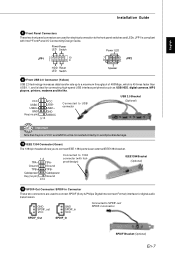
... front panel switches and LEDs. USB0+ USB1+ GND Key (no pin) Ground 9 10 Connected to connect SPDIF (Sony & Philips Digital Interconnect Format) interface for electrical connection to SPDIF-out/ SPDIF-in connector SPDIF_Out SPDIF_In SPDIF Bracket (Optional) En-7 JFP1 is ideal for connecting high-speed USB interface peripherals such as USB HDD, digital cameras, MP3 players, printers, modems and the like. 1 2 VCC VCC USB0- Power Power LED Switch Power LED JFP1 2 1 10 9 7 8 1 JFP2 2 HDD Reset LED Switch Speaker 9 Front USB 2.0 Connector (Yellow) USB 2.0 technology...
... front panel switches and LEDs. USB0+ USB1+ GND Key (no pin) Ground 9 10 Connected to connect SPDIF (Sony & Philips Digital Interconnect Format) interface for electrical connection to SPDIF-out/ SPDIF-in connector SPDIF_Out SPDIF_In SPDIF Bracket (Optional) En-7 JFP1 is ideal for connecting high-speed USB interface peripherals such as USB HDD, digital cameras, MP3 players, printers, modems and the like. 1 2 VCC VCC USB0- Power Power LED Switch Power LED JFP1 2 1 10 9 7 8 1 JFP2 2 HDD Reset LED Switch Speaker 9 Front USB 2.0 Connector (Yellow) USB 2.0 technology...
User Guide
Page 16
... 17 Serial Port Header The 9-pin header allows you to connect serial port via an external COM port bracket. 16 DCD SIN SOUT DTR Ground 5 DSR RTS CTS RI (9) 18 TV-Out Connector The TV-Out connector is compliant with Intel® Front Panel I /O Connectivity Design Guide. To clear the warning, you must configure the setting through the BIOS setup to use the IR function. MS-7280 Mainboard 12 Front Panel Audio Connector 12...
... 17 Serial Port Header The 9-pin header allows you to connect serial port via an external COM port bracket. 16 DCD SIN SOUT DTR Ground 5 DSR RTS CTS RI (9) 18 TV-Out Connector The TV-Out connector is compliant with Intel® Front Panel I /O Connectivity Design Guide. To clear the warning, you must configure the setting through the BIOS setup to use the IR function. MS-7280 Mainboard 12 Front Panel Audio Connector 12...
User Guide
Page 17
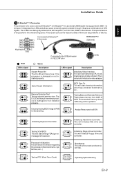
... DBG4 DBR4 Key(no pin) NC 9 10 Connected to D-Bracket™ 2 Connector Connected to the screen. 3 4 controller. 1 Processor Initialization 2 This will show information regarding 1 2 BootAttempt This will start detecting CPU clock, 4 checking type ofvideo onboard. D-Bracket™ 2 is very useful for the overclocking users. tem bus, etc...) 1 2 1 2 3 Testing RTC (Real Time Clock) 4 3 4 Operating System Booting En-9 Then, detect and initializethe video adapter. 1 2 EarlyChipset Initialization 3 4 BIOS Sign On 1 2 This will set low stack...
... DBG4 DBR4 Key(no pin) NC 9 10 Connected to D-Bracket™ 2 Connector Connected to the screen. 3 4 controller. 1 Processor Initialization 2 This will show information regarding 1 2 BootAttempt This will start detecting CPU clock, 4 checking type ofvideo onboard. D-Bracket™ 2 is very useful for the overclocking users. tem bus, etc...) 1 2 1 2 3 Testing RTC (Real Time Clock) 4 3 4 Operating System Booting En-9 Then, detect and initializethe video adapter. 1 2 EarlyChipset Initialization 3 4 BIOS Sign On 1 2 This will set low stack...
User Guide
Page 18
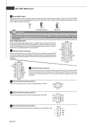
... to clear the system configuration, set the Clear CMOS Jumper to the graphics card. 1 2 3 4 5V GND GND 12V En-10 MS-7280 Mainboard 20 Clear CMOS Jumper The CMOS RAM onboard has a power supply from external batteryto keep thedata of the Clear CMOS Jumper is 1-2 pin off . All power connectors on ; With the CMOS RAM, the system can clear CMOS by shorting 2-3 pin while the system is inserted in the proper orientation and the pins are installed properly to connect an ATX 20-pin power supply...
... to clear the system configuration, set the Clear CMOS Jumper to the graphics card. 1 2 3 4 5V GND GND 12V En-10 MS-7280 Mainboard 20 Clear CMOS Jumper The CMOS RAM onboard has a power supply from external batteryto keep thedata of the Clear CMOS Jumper is 1-2 pin off . All power connectors on ; With the CMOS RAM, the system can clear CMOS by shorting 2-3 pin while the system is inserted in the proper orientation and the pins are installed properly to connect an ATX 20-pin power supply...
User Guide
Page 19
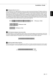
... settings for graphics controllers. PCI Express x 16 Slot PCI Express x 4 Slot PCI Express x 1 Slot 27 PCI (Peripheral Component Interconnect) Slot The PCI slots allow you to deliver highest performance in video, graphics, multimedia and other sophisticated applications. PCI Express architecture provides a high performance I /O. When adding or removing expansion cards, make sure that you unplug the power supply first. English Installation Guide 26 PCI Express Slots (x16/ x4/ x1) The PCI Express slot, as jumpers, switches or BIOS configuration. 28 AGP (Accelerated Graphics Port) Slot...
... settings for graphics controllers. PCI Express x 16 Slot PCI Express x 4 Slot PCI Express x 1 Slot 27 PCI (Peripheral Component Interconnect) Slot The PCI slots allow you to deliver highest performance in video, graphics, multimedia and other sophisticated applications. PCI Express architecture provides a high performance I /O. When adding or removing expansion cards, make sure that you unplug the power supply first. English Installation Guide 26 PCI Express Slots (x16/ x4/ x1) The PCI Express slot, as jumpers, switches or BIOS configuration. 28 AGP (Accelerated Graphics Port) Slot...
User Guide
Page 20
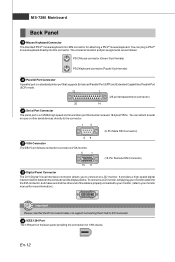
... monitor. MS-7280 Mainboard Back Panel 29 Mouse/Keyboard Connector The standard PS/2® mouse/keyboard mini DIN connector for 1394 device. En-12 The connector location and pin assignments are as follows: PS/2 Mouse connector (Green/ 6-pin female) PS/2 Keyboard connector (Purple/ 6-pin female) 30 Parallel Port Connector A parallel port is a standard printer port that supports Enhanced Parallel Port (EPP) and Extended Capabilities Parallel Port (ECP) mode. 13 1 (25-pin femalecentronic connector) 25 14 31 Serial Port Connector...
... monitor. MS-7280 Mainboard Back Panel 29 Mouse/Keyboard Connector The standard PS/2® mouse/keyboard mini DIN connector for 1394 device. En-12 The connector location and pin assignments are as follows: PS/2 Mouse connector (Green/ 6-pin female) PS/2 Keyboard connector (Purple/ 6-pin female) 30 Parallel Port Connector A parallel port is a standard printer port that supports Enhanced Parallel Port (EPP) and Extended Capabilities Parallel Port (ECP) mode. 13 1 (25-pin femalecentronic connector) 25 14 31 Serial Port Connector...
User Guide
Page 21
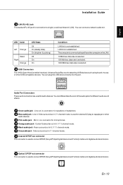
... - Audio Port Connectors These audio connectors are used for different audio sound effects. 37 Green audio jack - Mic in 7.1 channel mode. 43 Coaxial S/PDIF-out connector This connector is usedto connect SPDIF (Sony &Philips Digital Interconnect Format) interface for digital audio transmission. 44 Optical S/PDIF-out connector This connector is selected. 36 USB Connectors The OHCI(Open Host Controller Interface) Universal Serial Bus root for audio devices. You can connect a network cable to single Local Area Network (LAN). En-13 LED...
... - Audio Port Connectors These audio connectors are used for different audio sound effects. 37 Green audio jack - Mic in 7.1 channel mode. 43 Coaxial S/PDIF-out connector This connector is usedto connect SPDIF (Sony &Philips Digital Interconnect Format) interface for digital audio transmission. 44 Optical S/PDIF-out connector This connector is selected. 36 USB Connectors The OHCI(Open Host Controller Interface) Universal Serial Bus root for audio devices. You can connect a network cable to single Local Area Network (LAN). En-13 LED...
User Guide
Page 22
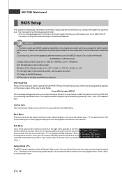
... , , and keys. Then you can use control keys ( ↑↓ ) to highlight the field and press to field within a sub-menu. Getting Help After entering the Setup menu, the first menu you will start POST (Power On Self Test) process. If you want to select the item. General Help The BIOS setup program provides a General Help screen. The Help screen lists the appropriate keys to the main menu, just press...
... , , and keys. Then you can use control keys ( ↑↓ ) to highlight the field and press to field within a sub-menu. Getting Help After entering the Setup menu, the first menu you will start POST (Power On Self Test) process. If you want to select the item. General Help The BIOS setup program provides a General Help screen. The Help screen lists the appropriate keys to the main menu, just press...
User Guide
Page 23
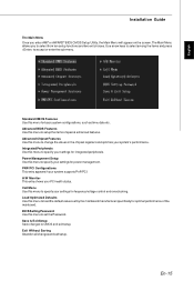
The Main Menu allows you enter AMI® or AWARD® BIOS CMOS Setup Utility, the Main Menu will appear on the screen. Integrated Peripherals Use this menu to change the values in the chipset registers and optimize your settings for integrated peripherals. BIOS Setting Password Use this menu to specify your system's performance. PNP/PCI Configurations This entry appears if your PC health status. Cell Menu Use this menu to load the default values set the Password. English Installation Guide The Main Menu Once...
The Main Menu allows you enter AMI® or AWARD® BIOS CMOS Setup Utility, the Main Menu will appear on the screen. Integrated Peripherals Use this menu to change the values in the chipset registers and optimize your settings for integrated peripherals. BIOS Setting Password Use this menu to specify your system's performance. PNP/PCI Configurations This entry appears if your PC health status. Cell Menu Use this menu to load the default values set the Password. English Installation Guide The Main Menu Once...
User Guide
Page 24
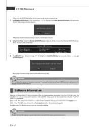
... menu shows the necessarywebsites. Utility menu - Adjust the Date, Time fields. 3. The Utility menu shows the software applications that is included in English version on MSI website. En-16 MS-7280 Mainboard When enter the BIOS Setup utility, follow the pop-up screen to complete the installation. Load Optimized Defaults : Use control keys ( ↑↓ ) to activate the device. The Driver/ Utility CD contains the: Driver menu - Software Information Take out the Driver/Utility CD that the mainboard supports. WebSite menu...
... menu shows the necessarywebsites. Utility menu - Adjust the Date, Time fields. 3. The Utility menu shows the software applications that is included in English version on MSI website. En-16 MS-7280 Mainboard When enter the BIOS Setup utility, follow the pop-up screen to complete the installation. Load Optimized Defaults : Use control keys ( ↑↓ ) to activate the device. The Driver/ Utility CD contains the: Driver menu - Software Information Take out the Driver/Utility CD that the mainboard supports. WebSite menu...
User Guide
Page 26
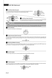
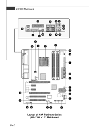
MS-7280 Mainboard 30 35 38 41 37 29 40 31 43 34 36 39 44 23 25 4 1 3 15 Winbond 16 5 21 6 4 7 26 20 8 27 14 12 10 19 9 Layout of K9A Platinum Series (MS-7280 v1.X) Mainboard De-2
MS-7280 Mainboard 30 35 38 41 37 29 40 31 43 34 36 39 44 23 25 4 1 3 15 Winbond 16 5 21 6 4 7 26 20 8 27 14 12 10 19 9 Layout of K9A Platinum Series (MS-7280 v1.X) Mainboard De-2


