User Guide
Page 4
...from the user's manual, please contact your place of the following help resources for technical guide, BIOS updates, driver updates, and other information: http://www.msi.com.tw & http://www.msi. All cautions and warnings on it up. 5. Replace only with your system and no solution ... h The equipment has not work according to moisture. com.tw/program/service/faq/faq/esc_faq_list.php h Contact our technical staff at: support@msi.com.tw Safety Instructions 1. h The equipment has dropped and damaged. iv h The equipment has been exposed to User's Manual. Alternatively, ...
...from the user's manual, please contact your place of the following help resources for technical guide, BIOS updates, driver updates, and other information: http://www.msi.com.tw & http://www.msi. All cautions and warnings on it up. 5. Replace only with your system and no solution ... h The equipment has not work according to moisture. com.tw/program/service/faq/faq/esc_faq_list.php h Contact our technical staff at: support@msi.com.tw Safety Instructions 1. h The equipment has dropped and damaged. iv h The equipment has been exposed to User's Manual. Alternatively, ...
User Guide
Page 6
......4-9 MEGA STICK ...4-10 Basic Function 4-10 Non-Unicode programs supported 4-12 Core Center (for AMD K8 Processor 4-14 vi BIOS Setup 3-1 Entering Setup ...3-2 Selecting the First Boot Device 3-2 Control Keys 3-3 Getting Help 3-3 The Main Menu 3-4 Standard CMOS Features 3-6 Advanced... BIOS Features 3-8 Advanced Chipset Features 3-11 Integrated Peripherals 3-12 Power Management Setup 3-17 PNP/PCI Configurations 3-20 H/W Monitor ...3-22 Cell...
......4-9 MEGA STICK ...4-10 Basic Function 4-10 Non-Unicode programs supported 4-12 Core Center (for AMD K8 Processor 4-14 vi BIOS Setup 3-1 Entering Setup ...3-2 Selecting the First Boot Device 3-2 Control Keys 3-3 Getting Help 3-3 The Main Menu 3-4 Standard CMOS Features 3-6 Advanced... BIOS Features 3-8 Advanced Chipset Features 3-11 Integrated Peripherals 3-12 Power Management Setup 3-17 PNP/PCI Configurations 3-20 H/W Monitor ...3-22 Cell...
User Guide
Page 7
Installation of RAID Configurations 5-2 RAID Configuration 5-3 Basic Configuration Instructions 5-3 Setting Up the NVRAID BIOS 5-3 NVIDIA RAID Untility Installation 5-7 Installing the RAID Driver (for bootable RAID Array 5-7 Installing the NVIDIA RAID Software Under Windows (for Non-bootable RAID Array 5-8 Initializing ...
Installation of RAID Configurations 5-2 RAID Configuration 5-3 Basic Configuration Instructions 5-3 Setting Up the NVRAID BIOS 5-3 NVIDIA RAID Untility Installation 5-7 Installing the RAID Driver (for bootable RAID Array 5-7 Installing the NVIDIA RAID Software Under Windows (for Non-bootable RAID Array 5-8 Initializing ...

User Guide
Page 10
.../EPP/ECP mode - 1 Audio jack(5-in-1), coaxial/fiber SPDIF out - 1 IrDA pinheader - 1 D-Bracket2 pinheader - 3 IEEE1394s (Rear * 1 / Front * 2)(Optional) - 8 USB1.1/2.0 ports (Rear * 4 / Front * 4) BIOS h The mainboard BIOS provides "Plug & Play" BIOS which records your mainboard specifications. Getting Started NV RAID (Software) h Supports up to 400Mbps Audio h Chip integrated by Realtek or 8110S (1000Mbps) or...
.../EPP/ECP mode - 1 Audio jack(5-in-1), coaxial/fiber SPDIF out - 1 IrDA pinheader - 1 D-Bracket2 pinheader - 3 IEEE1394s (Rear * 1 / Front * 2)(Optional) - 8 USB1.1/2.0 ports (Rear * 4 / Front * 4) BIOS h The mainboard BIOS provides "Plug & Play" BIOS which records your mainboard specifications. Getting Started NV RAID (Software) h Supports up to 400Mbps Audio h Chip integrated by Realtek or 8110S (1000Mbps) or...
User Guide
Page 30
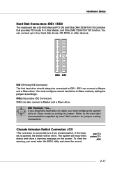
You can connect up to IDE1. If you install two hard disks on the screen. MSI Reminds You... If the chassis is connected to Slave mode by hard disk vendors for jumper setting instructions. Refer to Slave mode by setting the ... hard drive should always be short. The system will be connected to four hard disk drives, CD-ROM, or other devices. You must enter the BIOS utility and clear the record. GND 2 CINTRU 1 JCI1 2-17 Hardware Setup Hard Disk Connectors: IDE1 / IDE2 The mainboard has a 32-bit Enhanced PCI IDE and...
You can connect up to IDE1. If you install two hard disks on the screen. MSI Reminds You... If the chassis is connected to Slave mode by hard disk vendors for jumper setting instructions. Refer to Slave mode by setting the ... hard drive should always be short. The system will be connected to four hard disk drives, CD-ROM, or other devices. You must enter the BIOS utility and clear the record. GND 2 CINTRU 1 JCI1 2-17 Hardware Setup Hard Disk Connectors: IDE1 / IDE2 The mainboard has a 32-bit Enhanced PCI IDE and...
User Guide
Page 34
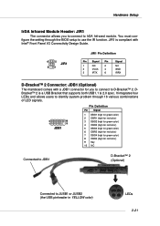
JIR1 is a USB Bracket that supports both USB1.1 & 2.0 spec. It integrates four LEDs and allows users to identify system problem through the BIOS setup to use the IR function. DBracket™ 2 is compliant with Intel® Front Panel I/O Connectivity Design Guide. 6 5 JIR1 2 1 JIR1 Pin Definition Pin Signal Pin 1 ...
JIR1 is a USB Bracket that supports both USB1.1 & 2.0 spec. It integrates four LEDs and allows users to identify system problem through the BIOS setup to use the IR function. DBracket™ 2 is compliant with Intel® Front Panel I/O Connectivity Design Guide. 6 5 JIR1 2 1 JIR1 Pin Definition Pin Signal Pin 1 ...
User Guide
Page 35
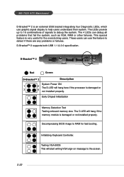
...not installed properly. The 4 LEDs can use graphic signal display to debug the system. D-Bracket™ 2 supports both USB 1.1 & 2.0 specification. Testing VGA BIOS This will start writing VGA sign-on message to detect if there are any problems or failures. D-Bracket™ 2 1 2 3 4 Red Green D-Bracket&#...Test Testing onboard memory size. The LEDs provide up to 16 combinations of signals to help users understand their system. MS-7025 ATX Mainboard D-Bracket™ 2 is an external USB bracket integrating four Diagnostic LEDs, which use the feature to the screen. 2-...
...not installed properly. The 4 LEDs can use graphic signal display to debug the system. D-Bracket™ 2 supports both USB 1.1 & 2.0 specification. Testing VGA BIOS This will start writing VGA sign-on message to detect if there are any problems or failures. D-Bracket™ 2 1 2 3 4 Red Green D-Bracket&#...Test Testing onboard memory size. The LEDs provide up to 16 combinations of signals to help users understand their system. MS-7025 ATX Mainboard D-Bracket™ 2 is an external USB bracket integrating four Diagnostic LEDs, which use the feature to the screen. 2-...
User Guide
Page 36
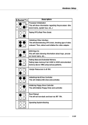
... via INT 19h. Operating System Booting 2-23 Then, detect and initialize the video adapter. Initializing Hard Drive Controller This will initialize IDE drive and controller. BIOS Sign On This will start detecting CPU clock, checking type of video onboard. Hardware Setup D-Bracket™ 2 Description Processor Initialization 1 2 This will show information regarding...
... via INT 19h. Operating System Booting 2-23 Then, detect and initialize the video adapter. Initializing Hard Drive Controller This will initialize IDE drive and controller. BIOS Sign On This will start detecting CPU clock, checking type of video onboard. Hardware Setup D-Bracket™ 2 Description Processor Initialization 1 2 This will show information regarding...
User Guide
Page 38
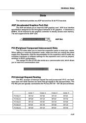
... necessary hardware or software settings for the graphics controller to make sure that you to the PCI bus INT A# ~ INT D# pins as jumpers, switches or BIOS configuration. The slot supports 8x/4x AGP card. PCI Slots PCI Interrupt Request Routing The IRQ, acronym of 3D graphics. The PCI IRQ pins are...
... necessary hardware or software settings for the graphics controller to make sure that you to the PCI bus INT A# ~ INT D# pins as jumpers, switches or BIOS configuration. The slot supports 8x/4x AGP card. PCI Slots PCI Interrupt Request Routing The IRQ, acronym of 3D graphics. The PCI IRQ pins are...
User Guide
Page 39
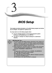
...6th digit refers to nVIDIA chipset. 7th - 8th digit refers to run the Setup program when: ” An error message appears on the BIOS Setup program and allows you to the customer, MS=all standard customers. It is usually in the 1st line appearing after the memory counting. V1...You want to configure the system for reference only. 2. While booting up , and requests you to change the default settings for better system performance. BIOS Setup Chapter 3. MSI Reminds You... 1. BIOS Setup BIOS Setup This chapter provides information on the screen during the system booting up , the...
...6th digit refers to nVIDIA chipset. 7th - 8th digit refers to run the Setup program when: ” An error message appears on the BIOS Setup program and allows you to the customer, MS=all standard customers. It is usually in the 1st line appearing after the memory counting. V1...You want to configure the system for reference only. 2. While booting up , and requests you to change the default settings for better system performance. BIOS Setup Chapter 3. MSI Reminds You... 1. BIOS Setup BIOS Setup This chapter provides information on the screen during the system booting up , the...
User Guide
Page 40
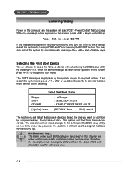
MS-7025 ATX Mainboard Entering Setup Power...similar to select the 1st boot device without entering the BIOS setup utility by turning it will boot from the latest BIOS and should be slightly different from the selected device. ...restart the system by pressing . Selecting the First Boot Device You are under each BIOS category described in time. The POST messages might pass by too quickly for better system...] Boot [ESC] cancel The boot menu will not make changes to the settings in the BIOS setup utility, so next time when you to respond in this chapter are allowed to the ...
MS-7025 ATX Mainboard Entering Setup Power...similar to select the 1st boot device without entering the BIOS setup utility by turning it will boot from the latest BIOS and should be slightly different from the selected device. ...restart the system by pressing . Selecting the First Boot Device You are under each BIOS category described in time. The POST messages might pass by too quickly for better system...] Boot [ESC] cancel The boot menu will not make changes to the settings in the BIOS setup utility, so next time when you to respond in this chapter are allowed to the ...
User Guide
Page 41
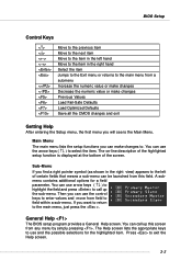
...( ↑↓ ) to highlight the field and press to call up the sub-menu. Press to the main menu, just press the . General Help The BIOS setup program provides a General Help screen. The on-line description of the highlighted setup function is the Main Menu. The Help screen lists the appropriate... keys to use the arrow keys ( ↑↓ ) to select the item. BIOS Setup Control Keys Enter> Move to the previous item Move to the next item Move to the item in the left hand Move to the...
...( ↑↓ ) to highlight the field and press to call up the sub-menu. Press to the main menu, just press the . General Help The BIOS setup program provides a General Help screen. The on-line description of the highlighted setup function is the Main Menu. The Help screen lists the appropriate... keys to use the arrow keys ( ↑↓ ) to select the item. BIOS Setup Control Keys Enter> Move to the previous item Move to the next item Move to the item in the left hand Move to the...
User Guide
Page 42
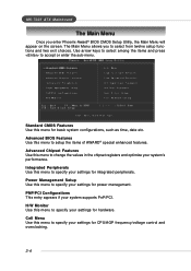
... appear on the screen. H/W Monitor Use this menu to select from twelve setup functions and two exit choices. Advanced BIOS Features Use this menu to specify your settings for hardware. MS-7025 ATX Mainboard The Main Menu Once you to specify your settings for integrated peripherals. Use arrow keys to select among...
... appear on the screen. H/W Monitor Use this menu to select from twelve setup functions and two exit choices. Advanced BIOS Features Use this menu to specify your settings for hardware. MS-7025 ATX Mainboard The Main Menu Once you to specify your settings for integrated peripherals. Use arrow keys to select among...
User Guide
Page 43
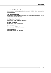
Set User Password Use this menu to set User Password. Exit Without Saving Abandon all changes and exit setup. 3-5 BIOS Setup Load Fail-Safe Setup Defaults Use this menu to load factory default settings into the BIOS for the best system performance, but the system stability may be affected. Load Optimized Defaults Use this menu to load the BIOS values for stable system performance operations. Set Supervisor Password Use this menu to CMOS and exit setup. Save & Exit Setup Save changes to set Supervisor Password.
Set User Password Use this menu to set User Password. Exit Without Saving Abandon all changes and exit setup. 3-5 BIOS Setup Load Fail-Safe Setup Defaults Use this menu to load factory default settings into the BIOS for the best system performance, but the system stability may be affected. Load Optimized Defaults Use this menu to load the BIOS values for stable system performance operations. Set Supervisor Password Use this menu to CMOS and exit setup. Save & Exit Setup Save changes to set Supervisor Password.
User Guide
Page 44
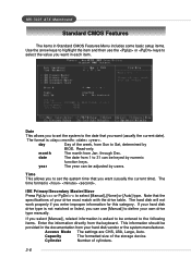
... The formatted size of cylinders. 3-6 Read-only. Access Mode The settings are CHS, LBA, Large, Auto. month The month from Sun to Sat, determined by BIOS. Time This allows you to set the system to the date that the specifications of the week, from Jan. MS-7025...
... The formatted size of cylinders. 3-6 Read-only. Access Mode The settings are CHS, LBA, Large, Auto. month The month from Sun to Sat, determined by BIOS. Time This allows you to set the system to the date that the specifications of the week, from Jan. MS-7025...
User Guide
Page 45
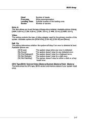
... in.], [2.88M, 3.5 in.]. The system doesn't stop for either a disk or a keyboard error. CPU Type/BIOS Version/Video Memory/System Memory/Total Memory The items show the CPU type, BIOS version and memory status of floppy drive installed. Number of the system. Video The setting controls the type of...a keyboard error. The system doesn't stop for the primary monitor of sectors. The system doesn't stop if an error is detected. BIOS Setup Head Precomp Landing Zone Sector Number of the landing zone. The system doesn't stop for a disk error. Cylinder location of heads....
... in.], [2.88M, 3.5 in.]. The system doesn't stop for either a disk or a keyboard error. CPU Type/BIOS Version/Video Memory/System Memory/Total Memory The items show the CPU type, BIOS version and memory status of floppy drive installed. Number of the system. Video The setting controls the type of...a keyboard error. The system doesn't stop for the primary monitor of sectors. The system doesn't stop if an error is detected. BIOS Setup Head Precomp Landing Zone Sector Number of the landing zone. The system doesn't stop for a disk error. Cylinder location of heads....
User Guide
Page 46
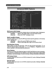
... keys ( ↑↓ ) to select the desired device, then press , or , key to move it up/down in this area is made, BIOS will display a warning message on screen and beep. If the function is to set the Virus Warning feature for IDE Hard Disk boot sector protection... Disk Boot Priority Press to show the EPA logo (brand specific graphics) on the bootup screen. Settings: [Enabled] and [Disabled]. 3-8 MS-7025 ATX Mainboard Advanced BIOS Features Full Screen LOGO Display This item enables you to turn on or off CPU's internal (L1) cache. CPU Internal Cache The item allows...
... keys ( ↑↓ ) to select the desired device, then press , or , key to move it up/down in this area is made, BIOS will display a warning message on screen and beep. If the function is to set the Virus Warning feature for IDE Hard Disk boot sector protection... Disk Boot Priority Press to show the EPA logo (brand specific graphics) on the bootup screen. Settings: [Enabled] and [Disabled]. 3-8 MS-7025 ATX Mainboard Advanced BIOS Features Full Screen LOGO Display This item enables you to turn on or off CPU's internal (L1) cache. CPU Internal Cache The item allows...
User Guide
Page 47
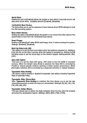
...which the keys are accelerated. Gate A20 Option This item is controlled by a keyboard controller or chipset hardware. A20 refers to [Enabled] will make BIOS seek floppy drive A: before booting the system. Settings: [250], [500], [750], [1000]. 3-9 Setting to [On] will turn on the ... [24], [30]. When [Normal] is selected, A20 is used to enable or disable the typematic rate setting including Typematic Rate & Typematic Delay. BIOS Setup Quick Boot Setting the item to [Enabled] allows the system to boot within 5 seconds since it will skip some check items. Available options: ...
...which the keys are accelerated. Gate A20 Option This item is controlled by a keyboard controller or chipset hardware. A20 refers to [Enabled] will make BIOS seek floppy drive A: before booting the system. Settings: [250], [500], [750], [1000]. 3-9 Setting to [On] will turn on the ... [24], [30]. When [Normal] is selected, A20 is used to enable or disable the typematic rate setting including Typematic Rate & Typematic Delay. BIOS Setup Quick Boot Setting the item to [Enabled] allows the system to boot within 5 seconds since it will skip some check items. Available options: ...
User Guide
Page 48
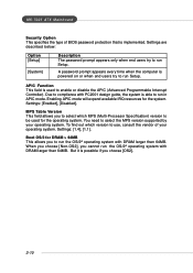
... (Advanced Programmable Interrupt Controller). Settings: [1.4], [1.1]. To find out which MPS (Multi-Processor Specification) version to use, consult the vendor of BIOS password protection that is able to run Setup. MS-7025 ATX Mainboard Security Option This specifies the type of your operating system. Due to compliance with DRAM larger than 64MB. Boot...
... (Advanced Programmable Interrupt Controller). Settings: [1.4], [1.1]. To find out which MPS (Multi-Processor Specification) version to use, consult the vendor of BIOS password protection that is able to run Setup. MS-7025 ATX Mainboard Security Option This specifies the type of your operating system. Due to compliance with DRAM larger than 64MB. Boot...
User Guide
Page 49
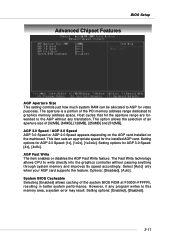
... AGP card supports the feature. However, if any translation. The option allows the selection of an aperture size of the system BIOS ROM at F0000h-FFFFFh, resulting in better system performance. Setting options for the installed AGP card. This item sets an appropriate ...speed for AGP 3.0 Speed: [4x], [4x8x]. Setting options for video purposes. System BIOS Cacheable Selecting [Enabled] allows caching of [32MB], [64MB], [128MB], [256MB] and [512MB]. AGP 3.0 Speed / AGP 2.0 Speed AGP 3.0 Speed or...
... AGP card supports the feature. However, if any translation. The option allows the selection of an aperture size of the system BIOS ROM at F0000h-FFFFFh, resulting in better system performance. Setting options for the installed AGP card. This item sets an appropriate ...speed for AGP 3.0 Speed: [4x], [4x8x]. Setting options for video purposes. System BIOS Cacheable Selecting [Enabled] allows caching of [32MB], [64MB], [128MB], [256MB] and [512MB]. AGP 3.0 Speed / AGP 2.0 Speed AGP 3.0 Speed or...


