User Guide
Page 4
... technical guide, BIOS updates, driver updates, and other information: http://www.msi.com.tw & http://www.msi. h The equipment has been exposed to the power inlet. 7. Alternatively, please try the following situations arises, get it may damage the equipment. Make sure the voltage of purchase or local distributor. fore connecting the equipment to moisture. Always Unplug the Power Cord before setting it...
... technical guide, BIOS updates, driver updates, and other information: http://www.msi.com.tw & http://www.msi. h The equipment has been exposed to the power inlet. 7. Alternatively, please try the following situations arises, get it may damage the equipment. Make sure the voltage of purchase or local distributor. fore connecting the equipment to moisture. Always Unplug the Power Cord before setting it...
User Guide
Page 5
...Recommended Memory Combination List 2-8 Installing DDR Modules 2-9 Power Supply 2-10 ATX 20-Pin Power Connector: ATX1 2-10 ATX 12V Power Connector: JPW1 2-10 Important Notification about Power Issue 2-11 Back Panel ...2-12 Mouse Connector (Green) / Keyboard Connector (Purple 2-12 IEEE1394 Port (Optional 2-12 Serial Port Connector 2-13 USB Connectors 2-13 LAN (RJ-45) Jack 2-14 Audio Port Connectors 2-14 Parallel Port Connector: LPT1 2-15 Connectors ...2-16 Floppy Disk Drive Connector: FDD1 2-16 Fan Power Connectors: CPUFAN1 / SFAN1 / SFAN2 / NBFAN1 2-16 Hard Disk Connectors: IDE1...
...Recommended Memory Combination List 2-8 Installing DDR Modules 2-9 Power Supply 2-10 ATX 20-Pin Power Connector: ATX1 2-10 ATX 12V Power Connector: JPW1 2-10 Important Notification about Power Issue 2-11 Back Panel ...2-12 Mouse Connector (Green) / Keyboard Connector (Purple 2-12 IEEE1394 Port (Optional 2-12 Serial Port Connector 2-13 USB Connectors 2-13 LAN (RJ-45) Jack 2-14 Audio Port Connectors 2-14 Parallel Port Connector: LPT1 2-15 Connectors ...2-16 Floppy Disk Drive Connector: FDD1 2-16 Fan Power Connectors: CPUFAN1 / SFAN1 / SFAN2 / NBFAN1 2-16 Hard Disk Connectors: IDE1...
User Guide
Page 6
.../Optimized Defaults 3-27 Set Supervisor/User Password 3-28 Chapter 4. IEEE 1394 Connectors: J1394_1 / J1394_2 (Optional 2-20 IrDA Infrared Module Header: JIR1 2-21 D-BracketTM 2 Connector: JDB1 (Optional 2-21 Jumpers ...2-24 Clear CMOS Jumper: JBAT1 2-24 Slots ...2-25 AGP (Accelerated Graphics Port) Slot 2-25 PCI (Peripheral Component Interconnect) Slots 2-25 PCI Interrupt Request Routing 2-25 Chapter 3. Introduction to DigiCell 4-1 Main ...4-2 H/W Diagnostic 4-4 Communication 4-5 Software Access Point 4-6 Terminology 4-6 Access Point Mode 4-7 WLAN Card Mode 4-8 Live Update...
.../Optimized Defaults 3-27 Set Supervisor/User Password 3-28 Chapter 4. IEEE 1394 Connectors: J1394_1 / J1394_2 (Optional 2-20 IrDA Infrared Module Header: JIR1 2-21 D-BracketTM 2 Connector: JDB1 (Optional 2-21 Jumpers ...2-24 Clear CMOS Jumper: JBAT1 2-24 Slots ...2-25 AGP (Accelerated Graphics Port) Slot 2-25 PCI (Peripheral Component Interconnect) Slots 2-25 PCI Interrupt Request Routing 2-25 Chapter 3. Introduction to DigiCell 4-1 Main ...4-2 H/W Diagnostic 4-4 Communication 4-5 Software Access Point 4-6 Terminology 4-6 Access Point Mode 4-7 WLAN Card Mode 4-8 Live Update...
User Guide
Page 7
... Software Under Windows (for Non-bootable RAID Array 5-8 Initializing and Using the Disk Array 5-9 RAID Drives Management 5-11 Viewing RAID Array Configurations 5-11 Setting Up a Spare RAID Disk 5-13 Rebuilding a RAID Mirrored Array 5-19 Chapter 6. nVIDIA RAID Introduction 5-1 Introduction ...5-2 System Requirement 5-2 RAID Arrays 5-2 Summary of Driver & Utility 6-1 Driver Installation 6-2 NVIDIA nForce3 System Driver 6-2 Realtek AC97 Audio Driver 6-5 Utility Installation 6-6 vii Audio Speaker Setting 4-16 Power on Agent 4-18 Power On 4-18 Power Off / Restart 4-19 Start...
... Software Under Windows (for Non-bootable RAID Array 5-8 Initializing and Using the Disk Array 5-9 RAID Drives Management 5-11 Viewing RAID Array Configurations 5-11 Setting Up a Spare RAID Disk 5-13 Rebuilding a RAID Mirrored Array 5-19 Chapter 6. nVIDIA RAID Introduction 5-1 Introduction ...5-2 System Requirement 5-2 RAID Arrays 5-2 Summary of Driver & Utility 6-1 Driver Installation 6-2 NVIDIA nForce3 System Driver 6-2 Realtek AC97 Audio Driver 6-5 Utility Installation 6-6 vii Audio Speaker Setting 4-16 Power on Agent 4-18 Power On 4-18 Power Off / Restart 4-19 Start...
User Guide
Page 9
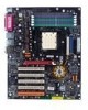
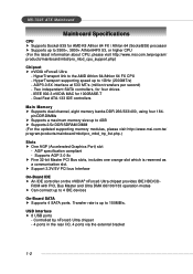
... bracket 1-2 USB Interface h 8 USB ports - Dual Fast ATA-133 IDE controllers Main Memory h Supports dual channel, eight memory banks DDR 266/333/400, using four 184- AGP3.0 8X interface at 533 MT/s (million transfers per second) - MS-7025 ATX Mainboard Mainboard Specifications CPU h Supports Socket-939 for AMD K8 Athlon 64 FX / Athlon 64 (Socket939) processor h Supports up to 4 IDE devices On-Board SATA h Supports 4 SATA ports. ROM with PIO, Bus Master and Ultra DMA 66/100/133 operation modes h Can connect up to...
... bracket 1-2 USB Interface h 8 USB ports - Dual Fast ATA-133 IDE controllers Main Memory h Supports dual channel, eight memory banks DDR 266/333/400, using four 184- AGP3.0 8X interface at 533 MT/s (million transfers per second) - MS-7025 ATX Mainboard Mainboard Specifications CPU h Supports Socket-939 for AMD K8 Athlon 64 FX / Athlon 64 (Socket939) processor h Supports up to 4 IDE devices On-Board SATA h Supports 4 SATA ports. ROM with PIO, Bus Master and Ultra DMA 66/100/133 operation modes h Can connect up to...

User Guide
Page 10
... boot from LAN, USB Device 1.1 & 2.0, and SATA HDD. 1-3 Direct Sound AC97 audio - 7.1 Channel output - 1 CD-In On-Board Peripherals h On-Board Peripherals include: - 1 floppy port supports 1 FDD with 360K, 720K, 1.2M, 1.44M and 2.88Mbytes - 1 serial port (COMA ) - 1 parallel port supporting SPP/EPP/ECP mode - 1 Audio jack(5-in-1), coaxial/fiber SPDIF out - 1 IrDA pinheader - 1 D-Bracket2 pinheader - 3 IEEE1394s (Rear * 1 / Front * 2)(Optional) - 8 USB1.1/2.0 ports (Rear * 4 / Front * 4) BIOS h The mainboard BIOS provides "Plug & Play" BIOS which records your mainboard specifications. RAID...
... boot from LAN, USB Device 1.1 & 2.0, and SATA HDD. 1-3 Direct Sound AC97 audio - 7.1 Channel output - 1 CD-In On-Board Peripherals h On-Board Peripherals include: - 1 floppy port supports 1 FDD with 360K, 720K, 1.2M, 1.44M and 2.88Mbytes - 1 serial port (COMA ) - 1 parallel port supporting SPP/EPP/ECP mode - 1 Audio jack(5-in-1), coaxial/fiber SPDIF out - 1 IrDA pinheader - 1 D-Bracket2 pinheader - 3 IEEE1394s (Rear * 1 / Front * 2)(Optional) - 8 USB1.1/2.0 ports (Rear * 4 / Front * 4) BIOS h The mainboard BIOS provides "Plug & Play" BIOS which records your mainboard specifications. RAID...
User Guide
Page 20
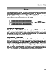
... high performance PC, workstations and servers. Hardware Setup Memory The mainboard provides 4 slots for 184-pin DDR SDRAM DIMM (Double In-Line Memory Module) modules and supports the memory size up to a maximum size of different type and density on different-channel DDR DIMMs. However, the same type and density memory modules are some rules while using dual-channel DDR, or instability may install memory modules of 1GB. You can install...
... high performance PC, workstations and servers. Hardware Setup Memory The mainboard provides 4 slots for 184-pin DDR SDRAM DIMM (Double In-Line Memory Module) modules and supports the memory size up to a maximum size of different type and density on different-channel DDR DIMMs. However, the same type and density memory modules are some rules while using dual-channel DDR, or instability may install memory modules of 1GB. You can install...
User Guide
Page 38
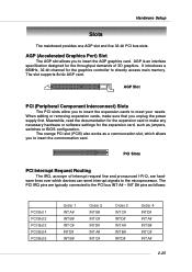
... works as jumpers, switches or BIOS configuration. When adding or removing expansion cards, make any necessary hardware or software settings for the graphics controller to insert the communcation card. The slot supports 8x/4x AGP card. It introduces a 66MHz, 32-bit channel for the expansion card, such as a communcation slot, which devices can send interrupt signals to the microprocessor. AGP Slot PCI (Peripheral Component Interconnect) Slots The PCI slots allow you to directly access main memory. AGP (Accelerated Graphics Port) Slot...
... works as jumpers, switches or BIOS configuration. When adding or removing expansion cards, make any necessary hardware or software settings for the graphics controller to insert the communcation card. The slot supports 8x/4x AGP card. It introduces a 66MHz, 32-bit channel for the expansion card, such as a communcation slot, which devices can send interrupt signals to the microprocessor. AGP Slot PCI (Peripheral Component Interconnect) Slots The PCI slots allow you to directly access main memory. AGP (Accelerated Graphics Port) Slot...
User Guide
Page 40
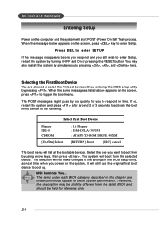
... the First Boot Device You are under continuous update for reference only. 3-2 MS-7025 ATX Mainboard Entering Setup Power on the computer and the system will not make changes to the settings in the BIOS setup utility, so next time when you power on the system, it OFF and On or pressing the RESET button. When the message below appears on the screen, press to trigger the boot menu.
... the First Boot Device You are under continuous update for reference only. 3-2 MS-7025 ATX Mainboard Entering Setup Power on the computer and the system will not make changes to the settings in the BIOS setup utility, so next time when you power on the system, it OFF and On or pressing the RESET button. When the message below appears on the screen, press to trigger the boot menu.
User Guide
Page 44
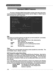
... the keyboard. year The year can be entered to the date that the specifications of cylinders. 3-6 Access Mode The settings are CHS, LBA, Large, Auto. The hard disk will not work properly if you want in the documentation from Sun to select [Manual], [None] or [Auto] type. If you can be provided in each item. day Day of the storage device. This information should be keyed...
... the keyboard. year The year can be entered to the date that the specifications of cylinders. 3-6 Access Mode The settings are CHS, LBA, Large, Auto. The hard disk will not work properly if you want in the documentation from Sun to select [Manual], [None] or [Auto] type. If you can be provided in each item. day Day of the storage device. This information should be keyed...
User Guide
Page 48
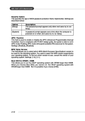
... design guide, the system is implemented. Enabling APIC mode will expand available IRQ resources for the operating system. You need to use, consult the vendor of BIOS password protection that is able to run Setup. APIC Function This field is possible if you to select which version to select the MPS version supported by your operating system. Settings: [Enabled], [Disabled]. Boot OS/2 for DRAM > 64MB...
... design guide, the system is implemented. Enabling APIC mode will expand available IRQ resources for the operating system. You need to use, consult the vendor of BIOS password protection that is able to run Setup. APIC Function This field is possible if you to select which version to select the MPS version supported by your operating system. Settings: [Enabled], [Disabled]. Boot OS/2 for DRAM > 64MB...
User Guide
Page 49
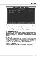
... system performance. This item sets an appropriate speed for AGP 2.0 Speed: [1x], [1x2x], [1x2x4x]. Setting options for video purposes. Select [Auto] only when your AGP card supports the feature. AGP Fast Write The item enables or disables the AGP Fast Write feature. The Fast Write technology allows CPU to this memory area, a system error may result. Options: [Disabled], [Auto]. BIOS Setup Advanced Chipset Features AGP Aperture Size This setting controls just how much system...
... system performance. This item sets an appropriate speed for AGP 2.0 Speed: [1x], [1x2x], [1x2x4x]. Setting options for video purposes. Select [Auto] only when your AGP card supports the feature. AGP Fast Write The item enables or disables the AGP Fast Write feature. The Fast Write technology allows CPU to this memory area, a system error may result. Options: [Disabled], [Auto]. BIOS Setup Advanced Chipset Features AGP Aperture Size This setting controls just how much system...
User Guide
Page 51
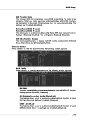
... [Disabled]. The settings are : [Enabled], [Disabled]. Onboard Device Press to enter the sub-menu and the following screen appears: IDE RAID This item is used to enable or disable the RAID function for faster drive accesses. SATA 1/2/3/4 RAID This feature allows users to enable or disable the DMA transfer function of the IDE Hard Drive. The settings are : [Enabled], [Disabled]. The settings are : [Enabled], [Disabled]. Setting options: [Enabled], [Disabled]. BIOS Setup IDE Prefetch Mode The onboard IDE drive interfaces support IDE prefetching, for each IDE hard disk drive...
... [Disabled]. The settings are : [Enabled], [Disabled]. Onboard Device Press to enter the sub-menu and the following screen appears: IDE RAID This item is used to enable or disable the RAID function for faster drive accesses. SATA 1/2/3/4 RAID This feature allows users to enable or disable the DMA transfer function of the IDE Hard Drive. The settings are : [Enabled], [Disabled]. The settings are : [Enabled], [Disabled]. Setting options: [Enabled], [Disabled]. BIOS Setup IDE Prefetch Mode The onboard IDE drive interfaces support IDE prefetching, for each IDE hard disk drive...
User Guide
Page 52
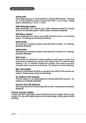
...you to enable or disable onchip Serial-ATA controller 3 & 4. Setting options: [Enabled], [Disabled]. Primary Graphics Adapter Initialize the AGP video display before initializing any other controller cards to connect an audio device. Thus the AGP display becomes the primary display. The settings are : [Auto], [Disabled]. Settings: [Enabled], [Disabled]. The settings are : [Enabled], [Disabled]. Onboard Giga LAN (Optional) This setting controls the onboard Giga LAN controller. USB Mouse Support Select [Enabled] if you want to use a USB-interfaced keyboard or storage device in the...
...you to enable or disable onchip Serial-ATA controller 3 & 4. Setting options: [Enabled], [Disabled]. Primary Graphics Adapter Initialize the AGP video display before initializing any other controller cards to connect an audio device. Thus the AGP display becomes the primary display. The settings are : [Auto], [Disabled]. Settings: [Enabled], [Disabled]. The settings are : [Enabled], [Disabled]. Onboard Giga LAN (Optional) This setting controls the onboard Giga LAN controller. USB Mouse Support Select [Enabled] if you want to use a USB-interfaced keyboard or storage device in the...
User Guide
Page 60
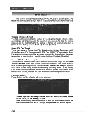
...), the fans will speed up for cooling down to keep the temperatures stable. Monitor function is available only if there is once opened. On the contrary if the current temperatures reach the minimum threshold (the set the field to [Enabled] later. MS-7025 ATX Mainboard H/W Monitor This section shows the status of the monitored hardware devices/components such as CPU voltage, temperatures and all fans' speeds. 3-22 Setting options: [Enabled], [Reset], [Disabled].
...), the fans will speed up for cooling down to keep the temperatures stable. Monitor function is available only if there is once opened. On the contrary if the current temperatures reach the minimum threshold (the set the field to [Enabled] later. MS-7025 ATX Mainboard H/W Monitor This section shows the status of the monitored hardware devices/components such as CPU voltage, temperatures and all fans' speeds. 3-22 Setting options: [Enabled], [Reset], [Disabled].
User Guide
Page 61
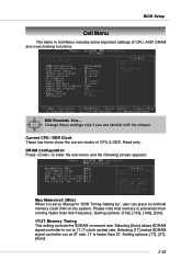
... are familiar with the chipset. Setting options: [1T], [2T], [Auto]. 3-23 BIOS Setup Cell Menu The items in "DDR Timing Setting by", user can place an artificial memory clock limit on the system. Setting options: [100], [133], [166], [200]. 1T/2T Memory Timing This setting controls the SDRAM command rate. MSI Reminds You... Current CPU / DDR Clock These two items show the current clocks of CPU, AGP, DRAM and overclocking functions. Selecting [1T...
... are familiar with the chipset. Setting options: [1T], [2T], [Auto]. 3-23 BIOS Setup Cell Menu The items in "DDR Timing Setting by", user can place an artificial memory clock limit on the system. Setting options: [100], [133], [166], [200]. 1T/2T Memory Timing This setting controls the SDRAM command rate. MSI Reminds You... Current CPU / DDR Clock These two items show the current clocks of CPU, AGP, DRAM and overclocking functions. Selecting [1T...
User Guide
Page 62
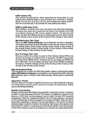
... DRAM is adjustable. Selecting [Manual] allows users to CAS (column address strobe). Dynamic Overclocking Dynamic Overclocking Technology is selected, the timing delay of data like 3D games or the video process, and the CPU frequency need to be shorten to increase the performance. When the motherboard detects CPU is temporarily suspending or staying in the low load balance, it . Setting options: [Auto], [5 Bus Clocks], [6 Bus Clocks], [7 Bus Clocks], [8 Bus Clocks], [9 Bus Clocks], [10 Bus Clocks], [11 Bus Clocks], [12 Bus Clocks...
... DRAM is adjustable. Selecting [Manual] allows users to CAS (column address strobe). Dynamic Overclocking Dynamic Overclocking Technology is selected, the timing delay of data like 3D games or the video process, and the CPU frequency need to be shorten to increase the performance. When the motherboard detects CPU is temporarily suspending or staying in the low load balance, it . Setting options: [Auto], [5 Bus Clocks], [6 Bus Clocks], [7 Bus Clocks], [8 Bus Clocks], [9 Bus Clocks], [10 Bus Clocks], [11 Bus Clocks], [12 Bus Clocks...
User Guide
Page 63
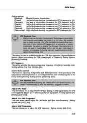
... suggest user to make sure that your CPU's from overheating due to enable or disable the FSB clock generator's Spread Spectrum feature. Setting options: [Enabled], [Disabled]. Setting options are : [200]~[300]. When overclocking the FSB, always set it 's better to disable the Dynamic Overclocking or to have the memories plugged in DIMM1. MSI Reminds You... BIOS Setup Setting options: [Disabled] [Private] [Sergeant] [Captain] [Colonel] [General] [Commander] Disable Dynamic Overclocking. 1st level of overclocking, increasing the CPU frequency by...
... suggest user to make sure that your CPU's from overheating due to enable or disable the FSB clock generator's Spread Spectrum feature. Setting options: [Enabled], [Disabled]. Setting options are : [200]~[300]. When overclocking the FSB, always set it 's better to disable the Dynamic Overclocking or to have the memories plugged in DIMM1. MSI Reminds You... BIOS Setup Setting options: [Disabled] [Private] [Sergeant] [Captain] [Colonel] [General] [Commander] Disable Dynamic Overclocking. 1st level of overclocking, increasing the CPU frequency by...

User Guide
Page 75
... the main menu and the Live Update program will appear on the update instructions, insert the companion CD and refer to the "Live Update Guide" under the "Manual" Tab. 4-9 If the product you purchased does not support any of the OSD products online. Live BIOS - Updates the firmware of the functions listed above, a "sorry" message is a tool used to detect and update your BIOS/ drivers/VGA BIOS/VGA Driver/OSD/Utility online...
... the main menu and the Live Update program will appear on the update instructions, insert the companion CD and refer to the "Live Update Guide" under the "Manual" Tab. 4-9 If the product you purchased does not support any of the OSD products online. Live BIOS - Updates the firmware of the functions listed above, a "sorry" message is a tool used to detect and update your BIOS/ drivers/VGA BIOS/VGA Driver/OSD/Utility online...
User Guide
Page 93
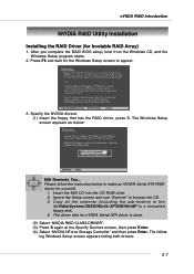
... Devices screen, then press Enter. (4) Select "NVIDIA NForce Storage Controller" and then press Enter. The following Windows Setup screen appears listing both drivers: 5-7 Specify the NVIDIA drivers: (1) Insert the floppy that has the RAID driver, press S. Ignore the Setup screen and use "Explorer" to a formatted floppy disk. 4. nVIDIA RAID Introduction NVIDIA RAID Utility Installation Installing the RAID Driver (for yourself. 1. After you complete the RAID BIOS setup, boot from the Windows CD, and the Windows Setup program starts. 2. Please follow the instruction below : MSI...
... Devices screen, then press Enter. (4) Select "NVIDIA NForce Storage Controller" and then press Enter. The following Windows Setup screen appears listing both drivers: 5-7 Specify the NVIDIA drivers: (1) Insert the floppy that has the RAID driver, press S. Ignore the Setup screen and use "Explorer" to a formatted floppy disk. 4. nVIDIA RAID Introduction NVIDIA RAID Utility Installation Installing the RAID Driver (for yourself. 1. After you complete the RAID BIOS setup, boot from the Windows CD, and the Windows Setup program starts. 2. Please follow the instruction below : MSI...

