User Guide
Page 10
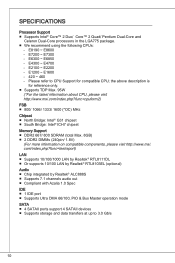
... DMA 66/100, PIO & Bus Master operation mode SATA ■ 4 SATAII ports support 4 SATAII devices ■ Supports storage and data transfers at up to CPU Support for reference only. ■ Supports TDP Max. 95W (*For the latest information about CPU, please visit http://www.msi.com/index.php?func=cpuform2) FSB ■ 800/ 1066/ 1333/ 1600 (*OC...
... DMA 66/100, PIO & Bus Master operation mode SATA ■ 4 SATAII ports support 4 SATAII devices ■ Supports storage and data transfers at up to CPU Support for reference only. ■ Supports TDP Max. 95W (*For the latest information about CPU, please visit http://www.msi.com/index.php?func=cpuform2) FSB ■ 800/ 1066/ 1333/ 1600 (*OC...
User Guide
Page 15
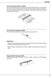
Floppy Disk Drive Connector: FDD1 This connector supports 360 KB, 720 KB, 1.2 MB, 1.44 MB or 2.88 MB floppy disk drive....113.2G6V1V.rP7o1.SuG81-n.rO9Gdo2.NurG0o2n#.ruR1do2n.eu+2ds2n5.+3dV2.5+4V5.GVround ATX 4-Pin Power Connector: JPWR2 This 12V power connector is used to provide power to the CPU. 2.G1.rGouronudnd 4.+31.+21V2V Important * Make sure that all the...) is inserted in the proper orientation and the pins are connected to proper ATX power supplies to connect an ATX 24-pin power supply. MS-7529 ATX 24-Pin Power Connector: JPWR1 This connector allows you to ensure stable operation ...
Floppy Disk Drive Connector: FDD1 This connector supports 360 KB, 720 KB, 1.2 MB, 1.44 MB or 2.88 MB floppy disk drive....113.2G6V1V.rP7o1.SuG81-n.rO9Gdo2.NurG0o2n#.ruR1do2n.eu+2ds2n5.+3dV2.5+4V5.GVround ATX 4-Pin Power Connector: JPWR2 This 12V power connector is used to provide power to the CPU. 2.G1.rGouronudnd 4.+31.+21V2V Important * Make sure that all the...) is inserted in the proper orientation and the pins are connected to proper ATX power supplies to connect an ATX 24-pin power supply. MS-7529 ATX 24-Pin Power Connector: JPWR1 This connector allows you to ensure stable operation ...
User Guide
Page 16
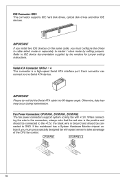
...fan with +12V. Fan Power Connectors: CPUFAN1, SYSFAN1, SYSFAN2 The fan power connectors support system cooling fan with speed sensor to IDE device documentation supplied by setting jumpers. Refer to take advantage of the CPU fan control. Otherwise, data loss may occur during transmission. the black wire is ... positive and should be connected to master / slave mode by the vendors for jumper setting instructions. IDE Connector: IDE1 This connector supports IDE hard disk drives, optical disk drives and other IDE devices. Important Please do not fold the Serial ATA cable into 90-degree...
...fan with +12V. Fan Power Connectors: CPUFAN1, SYSFAN1, SYSFAN2 The fan power connectors support system cooling fan with speed sensor to IDE device documentation supplied by setting jumpers. Refer to take advantage of the CPU fan control. Otherwise, data loss may occur during transmission. the black wire is ... positive and should be connected to master / slave mode by the vendors for jumper setting instructions. IDE Connector: IDE1 This connector supports IDE hard disk drives, optical disk drives and other IDE devices. Important Please do not fold the Serial ATA cable into 90-degree...
User Guide
Page 19
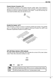
...you must enter the BIOS utility and clear the record. 1.C2.IGNTroRuUnd Parallel Port Header: JLPT1 This connector is a standard printer port that supports Enhanced Parallel Port (EPP) and Extended Capabilities Parallel Port (ECP) mode. 2.A4F.ED6R.#P8RI.1N#L0PI1T.TG2#_1r.GoS4u.1LrGon6INurd1.oGn#8ud...1P35NR1.DP7N41R.DP9N5R2.AD1NC26.DB3K2U7.#P5SE.YSLCT APS LED Status Indicator: LED2 (optional) The APS (Active Phase Switching) LED indicates the current CPU power phase mode. MS-7529 Chassis Intrusion Connector: JCI1 This connector connects to read. The parallel port is used to connect an ...
...you must enter the BIOS utility and clear the record. 1.C2.IGNTroRuUnd Parallel Port Header: JLPT1 This connector is a standard printer port that supports Enhanced Parallel Port (EPP) and Extended Capabilities Parallel Port (ECP) mode. 2.A4F.ED6R.#P8RI.1N#L0PI1T.TG2#_1r.GoS4u.1LrGon6INurd1.oGn#8ud...1P35NR1.DP7N41R.DP9N5R2.AD1NC26.DB3K2U7.#P5SE.YSLCT APS LED Status Indicator: LED2 (optional) The APS (Active Phase Switching) LED indicates the current CPU power phase mode. MS-7529 Chassis Intrusion Connector: JCI1 This connector connects to read. The parallel port is used to connect an ...
User Guide
Page 24
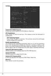
... you to enter the sub-menu. 24 Memory-Z Press to adjust the CPU ratio. This submenu shows the information of CPU/ Memory. This sub-menu shows the technologies that the installed CPU supported. Adjusted CPU Ratio This item allows you to adjust the CPU Ratio, please set the performance level of the microprocessor whether the computer...
... you to enter the sub-menu. 24 Memory-Z Press to adjust the CPU ratio. This submenu shows the information of CPU/ Memory. This sub-menu shows the technologies that the installed CPU supported. Adjusted CPU Ratio This item allows you to adjust the CPU Ratio, please set the performance level of the microprocessor whether the computer...


