User Guide
Page 3
...fore connecting the equipment to User's Manual. † The equipment has dropped and damaged. † The equipment has obvious sign of the power source and adjust properly 110/220V be noted. 10. All cautions and warnings on the enclosure are for future reference. 3. DO NOT LEAVETHIS...11. Safety Instructions 1. DO NOT COVER THE OPENINGS. 6. Replac e only with the same or equivalent type rec ommended by a service personnel: † The power cord or plug is damaged. † Liquid has penetrated into the opening that people can not get the equipment checked by the m an uf ac...
...fore connecting the equipment to User's Manual. † The equipment has dropped and damaged. † The equipment has obvious sign of the power source and adjust properly 110/220V be noted. 10. All cautions and warnings on the enclosure are for future reference. 3. DO NOT LEAVETHIS...11. Safety Instructions 1. DO NOT COVER THE OPENINGS. 6. Replac e only with the same or equivalent type rec ommended by a service personnel: † The power cord or plug is damaged. † Liquid has penetrated into the opening that people can not get the equipment checked by the m an uf ac...
User Guide
Page 4
... for help. FCC-B Radio Frequency Interference Statement T h is eq uip men t h as been tested and found to comply with Part 15 of the FCC Rules. power cord, if any interference received, including interference that may cause harmful interference to operate the equipment. Notice 2 Shielded interface cables and A.C. Operation is subject to...
... for help. FCC-B Radio Frequency Interference Statement T h is eq uip men t h as been tested and found to comply with Part 15 of the FCC Rules. power cord, if any interference received, including interference that may cause harmful interference to operate the equipment. Notice 2 Shielded interface cables and A.C. Operation is subject to...
User Guide
Page 8
... Processing Unit 2-2 Introduction to LGA 775 CPU 2-3 CPU & Cooler Installation 2-5 Memory ...2-6 Introduction to DDRII SDRAM 2-7 Memory Module Population Rules 2-7 Installing DDRII Modules 2-8 Power Supply ...2-8 ATX 24-Pin Power Connector: ATX 2-9 ATX 12V Power Connector: JPW/ JPWR 2-9 IEEE 1394 Port (optional 2-10 Mouse/Keyboard Connector 2-11 Back Panel ...2-11 Serial Port Connector: COM Port 2-11 USB Connectors...
... Processing Unit 2-2 Introduction to LGA 775 CPU 2-3 CPU & Cooler Installation 2-5 Memory ...2-6 Introduction to DDRII SDRAM 2-7 Memory Module Population Rules 2-7 Installing DDRII Modules 2-8 Power Supply ...2-8 ATX 24-Pin Power Connector: ATX 2-9 ATX 12V Power Connector: JPW/ JPWR 2-9 IEEE 1394 Port (optional 2-10 Mouse/Keyboard Connector 2-11 Back Panel ...2-11 Serial Port Connector: COM Port 2-11 USB Connectors...
User Guide
Page 9
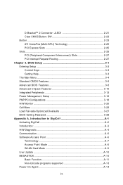
... A-7 Access Point Mode A-8 WLAN Card Mode A-9 Live Update ...A-10 MEGA STICK ...A-10 Basic Function A-11 Non-Unicode programs supported A-13 Power On Agent A-14 ix D-Bracket™ 2 Connector: JLED1 2-21 Clear CMOS Button: SW 2-23 Button ...2-23 ATi CrossFire (Multi-GPU...Getting Help 3-3 The Main Menu ...3-4 Standard CMOS Features 3-6 Advanced BIOS Features 3-8 Advanced Chipset Features 3-10 Integrated Peripherals 3-12 Power Management Setup 3-16 PNP/PCI Configurations 3-18 H/W Monitor ...3-20 Cell Menu ...3-22 Load Fail-safe/Optimized Deafaults 3-27 BIOS Setting Password 3-28...
... A-7 Access Point Mode A-8 WLAN Card Mode A-9 Live Update ...A-10 MEGA STICK ...A-10 Basic Function A-11 Non-Unicode programs supported A-13 Power On Agent A-14 ix D-Bracket™ 2 Connector: JLED1 2-21 Clear CMOS Button: SW 2-23 Button ...2-23 ATi CrossFire (Multi-GPU...Getting Help 3-3 The Main Menu ...3-4 Standard CMOS Features 3-6 Advanced BIOS Features 3-8 Advanced Chipset Features 3-10 Integrated Peripherals 3-12 Power Management Setup 3-16 PNP/PCI Configurations 3-18 H/W Monitor ...3-20 Cell Menu ...3-22 Load Fail-safe/Optimized Deafaults 3-27 BIOS Setting Password 3-28...
User Guide
Page 10
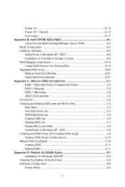
Power On A-15 Power Off / Restart A-16 Auto Login A-17 Appendix B. Intel ICH7HD SATA RAID B-1 Using the Intel Matrix Stroage Manager Option ROM B-2 BIOS Configuration B-2 Installing Software B-8 Install Driver ...
Power On A-15 Power Off / Restart A-16 Auto Login A-17 Appendix B. Intel ICH7HD SATA RAID B-1 Using the Intel Matrix Stroage Manager Option ROM B-2 BIOS Configuration B-2 Installing Software B-8 Install Driver ...
User Guide
Page 16
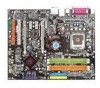
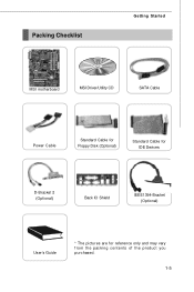
Packing Checklist Getting Started MSI motherboard MSI Driver/Utility CD SATA Cable Power Cable Standard Cable for Floppy Disk (Optional) Standard Cable for IDE Devices D-Bracket 2 (Optional) Back IO Shield IEEE1394-Bracket (Optional) User's Guide * The pictures are for reference only and may vary f rom the pac king c ontents of the product you p ur c h as ed . 1-5
Packing Checklist Getting Started MSI motherboard MSI Driver/Utility CD SATA Cable Power Cable Standard Cable for Floppy Disk (Optional) Standard Cable for IDE Devices D-Bracket 2 (Optional) Back IO Shield IEEE1394-Bracket (Optional) User's Guide * The pictures are for reference only and may vary f rom the pac king c ontents of the product you p ur c h as ed . 1-5
User Guide
Page 19
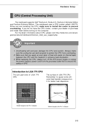
... Remember to purchase and install them before turning on it for better heat dispersion. While replacing the CPU, always turn off the ATX power supply or unplug the power supply's power cord from overheating. 2. The mainboard uses a CPU socket called LGA775. Important 1. Always make sure to install the cooler to protect... pin-pad side of CPU. Introduction to ensure the safety of LGA 775 CPU. For the latest information about CPU, please visit http://www.msi.com.tw/program/ produc ts /mainboar d/mbd/pr o_mbd_c pu _s upport .php. W hen you apply an even layer of LGA 775 CPU...
... Remember to purchase and install them before turning on it for better heat dispersion. While replacing the CPU, always turn off the ATX power supply or unplug the power supply's power cord from overheating. 2. The mainboard uses a CPU socket called LGA775. Important 1. Always make sure to install the cooler to protect... pin-pad side of CPU. Introduction to ensure the safety of LGA 775 CPU. For the latest information about CPU, please visit http://www.msi.com.tw/program/ produc ts /mainboar d/mbd/pr o_mbd_c pu _s upport .php. W hen you apply an even layer of LGA 775 CPU...
User Guide
Page 23
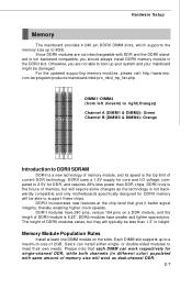
...respectively for DDRII memory will work as the technology is not backwardly compatible and only motherboards specifically designed for single-channel DDR, while both channels (in height. Otherwise, you ...M can install either single- For the updated supporting memory modules, please visit http://www.msi. The height of 2GB. Please note that give it better signal integrity, thereby enabling ...1.8V supply for core and I/O voltage, compared to 2.5V for DDR, and requires 28% less power than 1.3" in different color) populated with DDR and the DDRII standard is 5.25". DDR2 modules have ...
...respectively for DDRII memory will work as the technology is not backwardly compatible and only motherboards specifically designed for single-channel DDR, while both channels (in height. Otherwise, you ...M can install either single- For the updated supporting memory modules, please visit http://www.msi. The height of 2GB. Please note that give it better signal integrity, thereby enabling ...1.8V supply for core and I/O voltage, compared to 2.5V for DDR, and requires 28% less power than 1.3" in different color) populated with DDR and the DDRII standard is 5.25". DDR2 modules have ...
User Guide
Page 25
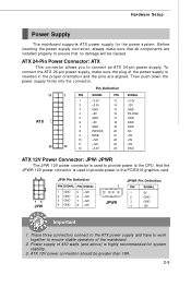
...PW R OK 20 NC 9 5VSB 21 +5V 10 +12V 22 +5V 12 11 +12V 12 +3.3V 23 +5V 24 GND ATX 12V Power Connector: JPW/ JPWR The JPW 12V power connector is inserted in the proper orientation and the pins are installed properly to ensure that no damage will be greater than... connector, always make sure the plug of the power supply is used to provide power to ensure stable operation of 450 watts (and above) is used to provide power to connect an ATX 24-pin power supply. These three connectors connect to the ATX power supply and have to work together to the PCIEX16 ...
...PW R OK 20 NC 9 5VSB 21 +5V 10 +12V 22 +5V 12 11 +12V 12 +3.3V 23 +5V 24 GND ATX 12V Power Connector: JPW/ JPWR The JPW 12V power connector is inserted in the proper orientation and the pins are installed properly to ensure that no damage will be greater than... connector, always make sure the plug of the power supply is used to provide power to ensure stable operation of 450 watts (and above) is used to provide power to connect an ATX 24-pin power supply. These three connectors connect to the ATX power supply and have to work together to the PCIEX16 ...
User Guide
Page 30
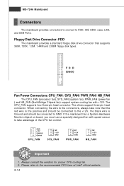
... connected to the +12V, the black wire is Ground and should be connected to GND. FD D (black) Fan Power Connectors: CPU_FAN / SYS_FAN / PWR_FAN / NB_FAN The CPU_FAN (processor fan), SYS_FAN (system fan), PW R_FAN (power fan ) and NB_FAN (NorthBridge Chipset fan) support system cooling fan with speed sensor to the connectors, always take...
... connected to the +12V, the black wire is Ground and should be connected to GND. FD D (black) Fan Power Connectors: CPU_FAN / SYS_FAN / PWR_FAN / NB_FAN The CPU_FAN (processor fan), SYS_FAN (system fan), PW R_FAN (power fan ) and NB_FAN (NorthBridge Chipset fan) support system cooling fan with speed sensor to the connectors, always take...
User Guide
Page 33
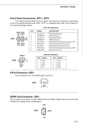
... for digital audio transmission. JFP1 is used to connect SPDIF (Sony & Philips Digital Interconnect Format) interface for CD-ROM audio connector. JFP1 Pin Definition PIN Power Power LED Switch 1 2 JFP1 2 1 10 3 9 4 5 HDD Reset 6 LED Switch 7 8 9 SIGNAL HD_LED_P FP PW R/SLP HD_LED_N FP PW R/SLP RST_SW_N PWR_SW_P...pull-up Hard disk active LED MSG LED pull-up Reset Switch low reference pull-down to GND Power Switch high reference pull-up Reset Switch high reference pull-up Power Switch low reference pull-down to the front panel switches and LEDs. JCD1 R GND L SPDIF-Out...
... for digital audio transmission. JFP1 is used to connect SPDIF (Sony & Philips Digital Interconnect Format) interface for CD-ROM audio connector. JFP1 Pin Definition PIN Power Power LED Switch 1 2 JFP1 2 1 10 3 9 4 5 HDD Reset 6 LED Switch 7 8 9 SIGNAL HD_LED_P FP PW R/SLP HD_LED_N FP PW R/SLP RST_SW_N PWR_SW_P...pull-up Hard disk active LED MSG LED pull-up Reset Switch low reference pull-down to GND Power Switch high reference pull-up Reset Switch high reference pull-up Power Switch low reference pull-down to the front panel switches and LEDs. JCD1 R GND L SPDIF-Out...
User Guide
Page 35
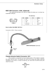
Pin Definition 2 10 1 J1394_1 PIN SIGNAL PIN 1 TPA+ 2 3 Ground 4 5 TPB+ 6 7 Cable power 8 9 Key (no pin) 10 SIGNAL TPAGround TPBCable power Ground How to attach the IEEE 1394 Port: Connected to J1394_1 (Green connector) Foolproof design IEEE1394 Bracket (Optional) Chassis Intrusion Switch Connector: JCI1 This connector ...
Pin Definition 2 10 1 J1394_1 PIN SIGNAL PIN 1 TPA+ 2 3 Ground 4 5 TPB+ 6 7 Cable power 8 9 Key (no pin) 10 SIGNAL TPAGround TPBCable power Ground How to attach the IEEE 1394 Port: Connected to J1394_1 (Green connector) Foolproof design IEEE1394 Bracket (Optional) Chassis Intrusion Switch Connector: JCI1 This connector ...
User Guide
Page 37
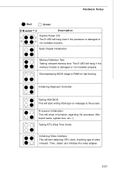
... the memory module is damaged or 3 4 not installed properly. Then, detect and initialize the video adapter. 2-21 Hardware Setup Red Green D-Bracket™ 2 Description System Power ON 1 2 The D-LED will hang here if the processor is damaged or not installed properly. Testing VGA BIOS This will start writing VGA sign-on...
... the memory module is damaged or 3 4 not installed properly. Then, detect and initialize the video adapter. 2-21 Hardware Setup Red Green D-Bracket™ 2 Description System Power ON 1 2 The D-LED will hang here if the processor is damaged or not installed properly. Testing VGA BIOS This will start writing VGA sign-on...
User Guide
Page 39
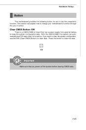
... function. W ith the CMOS RAM, the system can automatically boot OS every time it is a CMOS RAM on . Hardware Setup Button The motherboard provides the following button for you want to clear the system configuration, use of button. Clear CMOS Button: SW There is turned on board that...before clearing CMOS data. 2-23 SW Important Make sure that has a power supply from external battery to keep the system configuration data. This section will explain how to clear the data. Press the button to change your motherboard's function through the use the SW (Clear CMOS Button) to clear data...
... function. W ith the CMOS RAM, the system can automatically boot OS every time it is a CMOS RAM on . Hardware Setup Button The motherboard provides the following button for you want to clear the system configuration, use of button. Clear CMOS Button: SW There is turned on board that...before clearing CMOS data. 2-23 SW Important Make sure that has a power supply from external battery to keep the system configuration data. This section will explain how to clear the data. Press the button to change your motherboard's function through the use the SW (Clear CMOS Button) to clear data...
User Guide
Page 40
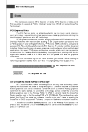
You can auto detect the CrossFire mode by software, therefore you unplug the power supply first. To utilize this technology, always install the CrossFire Edition graphics card in the Primary PCIE x16 (PEG1) slot and install the CrossFire... Edition graphics card in BIOS by ATI that you don't have to complete CrossFire: 1. W hen adding or removing expansion cards, make sure that allows the power of 4.0 GB/s over a PCI Express x1 lane for graphics controllers. Moreover, PCI Express architecture provides a high performance graphics infrastructure for Desktop Platforms doubling the...
You can auto detect the CrossFire mode by software, therefore you unplug the power supply first. To utilize this technology, always install the CrossFire Edition graphics card in the Primary PCIE x16 (PEG1) slot and install the CrossFire... Edition graphics card in BIOS by ATI that you don't have to complete CrossFire: 1. W hen adding or removing expansion cards, make sure that allows the power of 4.0 GB/s over a PCI Express x1 lane for graphics controllers. Moreover, PCI Express architecture provides a high performance graphics infrastructure for Desktop Platforms doubling the...
User Guide
Page 43
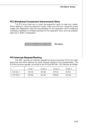
... configuration. Hardware Setup PCI (Peripheral Component Interconnect) Slots The PCI slots allow you to insert the expansion cards to make sure that you unplug the power supply first. Meanwhile, read the documentation for the expansion card, such as follows: PCI Slot 1 PCI Slot 2 Order 1 INT A# INT B# Order 2 INT B# INT C# Order 3 INT...
... configuration. Hardware Setup PCI (Peripheral Component Interconnect) Slots The PCI slots allow you to insert the expansion cards to make sure that you unplug the power supply first. Meanwhile, read the documentation for the expansion card, such as follows: PCI Slot 1 PCI Slot 2 Order 1 INT A# INT B# Order 2 INT B# INT C# Order 3 INT...
User Guide
Page 45
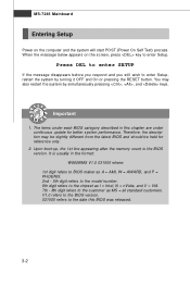
...RESET button. Important 1. V1.0 refers to the BIOS version. 031505 refers to the customer as MS = all standard customers. MS-7246 Mainboard Entering Setup Power on the screen, press key to enter Setup, restart the system by simultaneously pressing , , and keys. Upon boot-up, the 1st line appearing after...this BIOS was released. 3-2 It is the BIOS version. W hen the message below appears on the computer and the system will start POST (Power On Self Test) process. Press DEL to enter SETUP If the message disappears before you respond and you still wish to enter Setup. You ...
...RESET button. Important 1. V1.0 refers to the BIOS version. 031505 refers to the customer as MS = all standard customers. MS-7246 Mainboard Entering Setup Power on the screen, press key to enter Setup, restart the system by simultaneously pressing , , and keys. Upon boot-up, the 1st line appearing after...this BIOS was released. 3-2 It is the BIOS version. W hen the message below appears on the computer and the system will start POST (Power On Self Test) process. Press DEL to enter SETUP If the message disappears before you respond and you still wish to enter Setup. You ...
User Guide
Page 47
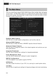
... of AWARD® special enhanced features. Cell Menu Use this menu to specify your settings for power management. Standard CMOS Features Use this menu to select from the eleven setup functions and two exit choices. Power Management Setup Use this menu for frequency/voltage control and overclocking. 3-4 MS-7246 Mainboard The Main...
... of AWARD® special enhanced features. Cell Menu Use this menu to specify your settings for power management. Standard CMOS Features Use this menu to select from the eleven setup functions and two exit choices. Power Management Setup Use this menu for frequency/voltage control and overclocking. 3-4 MS-7246 Mainboard The Main...
User Guide
Page 51
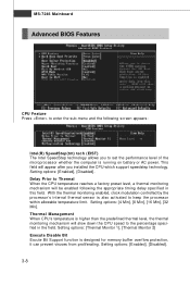
... the sub-menu and the following the appropriate timing delay specified in the field. Thermal Management W hen CPU's temperature is running on battery or AC power. This field will appear after you to set the performance level of the microprocessor whether the computer is higher than the predefined thermal level, the...
... the sub-menu and the following the appropriate timing delay specified in the field. Thermal Management W hen CPU's temperature is running on battery or AC power. This field will appear after you to set the performance level of the microprocessor whether the computer is higher than the predefined thermal level, the...
User Guide
Page 53
...Advanced Programmable Interrupt Controller). Setting options: [Yes], [No]. Boot Up NumLock LED This setting is to set the Num Lock status when the system is powered on . Setting to [On] will skip some check items. Setting options: [Enabled], [Disabled]. But it will turn on the Num Lock key when ...the system is powered on . MS-7246 Mainboard Quick Boot Setting the item to [Enabled] allows the system to boot within 5 seconds since it is possible if you ...
...Advanced Programmable Interrupt Controller). Setting options: [Yes], [No]. Boot Up NumLock LED This setting is to set the Num Lock status when the system is powered on . Setting to [On] will skip some check items. Setting options: [Enabled], [Disabled]. But it will turn on the Num Lock key when ...the system is powered on . MS-7246 Mainboard Quick Boot Setting the item to [Enabled] allows the system to boot within 5 seconds since it is possible if you ...

