

User Guide
Page 8
... Pentium 4/ Celeron D LGA 775 processors (For the latest information about CPU, please visit http:// www.msi.com.tw/cpusupport.htm) Supported FSB l 800 / 533 MHz Chipset l North Bridge: Intel® 945GZ chipset l South Bridge: Intel® ICH7 chipset Memory Support l DDR2 400/ 533 SDRAM (2GB Max) l 2 DDR2 DIMMs ...compatible components, please visit http:// www.msi.com.tw/testreport.htm) LAN l Supports 10/100 Mb/s Fast Ethernet by Realtek RTL 8100C l Or Supports 10/100/1000 Fast Ethermet by Realtek RTL 8110SC Audio l Chip integrated by Realtek ALC883, supports HD 5.1-channel audio-out l Or chip...
... Pentium 4/ Celeron D LGA 775 processors (For the latest information about CPU, please visit http:// www.msi.com.tw/cpusupport.htm) Supported FSB l 800 / 533 MHz Chipset l North Bridge: Intel® 945GZ chipset l South Bridge: Intel® ICH7 chipset Memory Support l DDR2 400/ 533 SDRAM (2GB Max) l 2 DDR2 DIMMs ...compatible components, please visit http:// www.msi.com.tw/testreport.htm) LAN l Supports 10/100 Mb/s Fast Ethernet by Realtek RTL 8100C l Or Supports 10/100/1000 Fast Ethermet by Realtek RTL 8110SC Audio l Chip integrated by Realtek ALC883, supports HD 5.1-channel audio-out l Or chip...
User Guide
Page 11
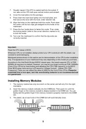
...the load lever lightly onto the load plate, and then secure the lever with the plastic cap covered to [Frequency/ Voltage Control]à[Adjust CPU FSB Frequency]. Mainboard photos shown in the DIMM slot. 3. However, you can barely see the golden finger if the memory module is ...properly inserted in this board supports CPU of FSB 800MHz at each side of your mainboard may let your CPU socket pin with the hook under retention tab. 10. Installing Memory Modules 1. You can adjust the value ...
...the load lever lightly onto the load plate, and then secure the lever with the plastic cap covered to [Frequency/ Voltage Control]à[Adjust CPU FSB Frequency]. Mainboard photos shown in the DIMM slot. 3. However, you can barely see the golden finger if the memory module is ...properly inserted in this board supports CPU of FSB 800MHz at each side of your mainboard may let your CPU socket pin with the hook under retention tab. 10. Installing Memory Modules 1. You can adjust the value ...
User Guide
Page 12
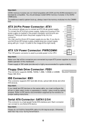
Floppy Disk Drive Connector: FDD1 This connector supports 360KB, 720KB, 1.2MB, 1.44MB or 2.88MB floppy disk drive. Important: If you install two IDE devices...12V +3.3V ATX 12V Power Connector: PWRCONN1 +12V +12V This 12V power connector is used to provide power to the CPU. You should always install DDR2 memory modules in the proper orientation and the pins are connected to proper ATX power supplies ... that all the connectors are aligned. Power supply of the mainboard. IDE Connector: IDE1 This connector supports IDE hard disk drives, optical disk drives and other IDE devices.
Floppy Disk Drive Connector: FDD1 This connector supports 360KB, 720KB, 1.2MB, 1.44MB or 2.88MB floppy disk drive. Important: If you install two IDE devices...12V +3.3V ATX 12V Power Connector: PWRCONN1 +12V +12V This 12V power connector is used to provide power to the CPU. You should always install DDR2 memory modules in the proper orientation and the pins are connected to proper ATX power supplies ... that all the connectors are aligned. Power supply of the mainboard. IDE Connector: IDE1 This connector supports IDE hard disk drives, optical disk drives and other IDE devices.
User Guide
Page 13
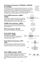
..., you to connect the front panel audio and is compliant with speed sensor to keep the data of the CPU fan control. Fan Power Connectors: CPUFAN1, SYSFAN1 & SYSFAN2 The fan power connectors support system cooling fan with Intel® Front Panel I/O Connectivity Design Guide. When connecting the wire to the connectors, always...
..., you to connect the front panel audio and is compliant with speed sensor to keep the data of the CPU fan control. Fan Power Connectors: CPUFAN1, SYSFAN1 & SYSFAN2 The fan power connectors support system cooling fan with Intel® Front Panel I/O Connectivity Design Guide. When connecting the wire to the connectors, always...
User Guide
Page 16
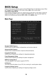
... respond and you still wish to enter Setup, restart the system by simultaneously pressing , , and keys. Integrated Peripherals Use this menu to specify your system supports PnP/PCI. PNP/PCI Configurations This entry appears if your settings for integrated peripherals. Power Management Setup Use this menu to specify your settings for... and the system will start POST (Power On Self Test) process. Main Page Standard CMOS Features Use this menu to setup the items of your CPU, fan, warning for basic system configurations, such as time, date etc.
... respond and you still wish to enter Setup, restart the system by simultaneously pressing , , and keys. Integrated Peripherals Use this menu to specify your system supports PnP/PCI. PNP/PCI Configurations This entry appears if your settings for integrated peripherals. Power Management Setup Use this menu to specify your settings for... and the system will start POST (Power On Self Test) process. Main Page Standard CMOS Features Use this menu to setup the items of your CPU, fan, warning for basic system configurations, such as time, date etc.


