User Guide
Page 4
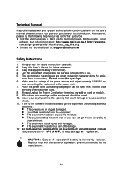
... this User's Manual for technical guide, BIOS updates, driver updates, and other information: http://www.msi.com.tw & http://www.msi. h Visit the MSI homepage & FAQ site for future reference. 3. Place the power cord such a way that could damage or cause electrical shock. 11. fore connecting the equipment to moisture. Technical Support If a problem arises with the same or equivalent type recommended by a service personnel: h The power...
... this User's Manual for technical guide, BIOS updates, driver updates, and other information: http://www.msi.com.tw & http://www.msi. h Visit the MSI homepage & FAQ site for future reference. 3. Place the power cord such a way that could damage or cause electrical shock. 11. fore connecting the equipment to moisture. Technical Support If a problem arises with the same or equivalent type recommended by a service personnel: h The power...
User Guide
Page 5
...2-3 CPU & Cooler Installation 2-4 Memory ...2-7 Introduction to DDR2 SDRAM 2-7 Memory Module Population Rules 2-8 Installing DDR2 Modules 2-8 Power Supply ...2-9 ATX 24-Pin Power Connector: ATX1 2-9 ATX 12V Power Connector: JPW1 2-9 Back Panel ...2-10 Mouse/Keyboard Connector 2-10 VGA Connector (Optional 2-10 Serial Port Connector 2-11 USB Connectors 2-11 LAN (RJ-45) Jack 2-12 Audio Port Connectors 2-12 Parallel Port Connector: LPT1 2-13 Connectors ...2-14 Floppy Disk Drive Connector: FDD1 2-14 Fan Power Connectors: CPUFAN2/SYSFAN1/NBFAN1/PWRFAN1 ....... 2-14 Hard Disk Connectors...
...2-3 CPU & Cooler Installation 2-4 Memory ...2-7 Introduction to DDR2 SDRAM 2-7 Memory Module Population Rules 2-8 Installing DDR2 Modules 2-8 Power Supply ...2-9 ATX 24-Pin Power Connector: ATX1 2-9 ATX 12V Power Connector: JPW1 2-9 Back Panel ...2-10 Mouse/Keyboard Connector 2-10 VGA Connector (Optional 2-10 Serial Port Connector 2-11 USB Connectors 2-11 LAN (RJ-45) Jack 2-12 Audio Port Connectors 2-12 Parallel Port Connector: LPT1 2-13 Connectors ...2-14 Floppy Disk Drive Connector: FDD1 2-14 Fan Power Connectors: CPUFAN2/SYSFAN1/NBFAN1/PWRFAN1 ....... 2-14 Hard Disk Connectors...
User Guide
Page 10
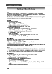
.... h Three 32-bit v2.3 Master PCI bus slots (support 3.3v/5v PCI bus interface). Supports AHCI controller with transfer rate up to 2GB memory size. 7058 ATX Mainboard Mainboard Specifications CPU h Supports Intel® Pentium 4 Prescott LGA775 processors in ICH6/ICH6R. - Supports PCI Express x16 interface. - Serial ATA 150 RAID 0, RAID 1 and Matrix RAID (for ICH6R only). 1-2 h Supports Dual channel DDR1 & DDR2 memory architecture. On-Board IDE h One Ultra DMA 66/100 IDE controllers integrated in ICH6/ICH6R. - Supports PIO, Bus Master operation modes. - Can connect up to...
.... h Three 32-bit v2.3 Master PCI bus slots (support 3.3v/5v PCI bus interface). Supports AHCI controller with transfer rate up to 2GB memory size. 7058 ATX Mainboard Mainboard Specifications CPU h Supports Intel® Pentium 4 Prescott LGA775 processors in ICH6/ICH6R. - Supports PCI Express x16 interface. - Serial ATA 150 RAID 0, RAID 1 and Matrix RAID (for ICH6R only). 1-2 h Supports Dual channel DDR1 & DDR2 memory architecture. On-Board IDE h One Ultra DMA 66/100 IDE controllers integrated in ICH6/ICH6R. - Supports PIO, Bus Master operation modes. - Can connect up to...
User Guide
Page 11
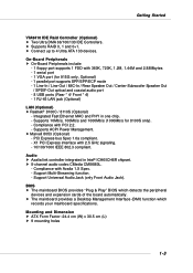
... / 8110S (Optional) - Supports ACPI Power Management. Support Multi-Streaming function. - h Supports RAID 0, 1 and 0+1. On-Board Peripherals h On-Board Peripherals include: - 1 floppy port supports 1 FDD with 2.5 GHz signaling. - 10/100/1000 IEEE 802.3 compliant. X1 PCI Express interface with 360K, 720K, 1.2M, 1.44M and 2.88Mbytes - 1 serial port - 1 VGA port (for 8100S only). - h Marvell 8053 (Optional) - PCI Express bus Spec 1.0a compliant. - Compliance with PCI 2.2. - BIOS h The mainboard BIOS provides "Plug & Play" BIOS which records your mainboard specifications...
... / 8110S (Optional) - Supports ACPI Power Management. Support Multi-Streaming function. - h Supports RAID 0, 1 and 0+1. On-Board Peripherals h On-Board Peripherals include: - 1 floppy port supports 1 FDD with 2.5 GHz signaling. - 10/100/1000 IEEE 802.3 compliant. X1 PCI Express interface with 360K, 720K, 1.2M, 1.44M and 2.88Mbytes - 1 serial port - 1 VGA port (for 8100S only). - h Marvell 8053 (Optional) - PCI Express bus Spec 1.0a compliant. - Compliance with PCI 2.2. - BIOS h The mainboard BIOS provides "Plug & Play" BIOS which records your mainboard specifications...
User Guide
Page 20
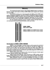
For the updated supporting memory modules, please visit http://www.msi. DDR2 uses a 1.8V supply for core and I/O voltage, compared to 2.5V for DDR1, and requires 28% less power than 1.3" in DDR1 slot (DIMM2 & DIMM4). DDR1 SDRAM is similar to support these chips. Wrong installation may cause damage of memory, but doubles the rate by transferring data twice per cycle. DDR2 modules have smaller and...
For the updated supporting memory modules, please visit http://www.msi. DDR2 uses a 1.8V supply for core and I/O voltage, compared to 2.5V for DDR1, and requires 28% less power than 1.3" in DDR1 slot (DIMM2 & DIMM4). DDR1 SDRAM is similar to support these chips. Wrong installation may cause damage of memory, but doubles the rate by transferring data twice per cycle. DDR2 modules have smaller and...
User Guide
Page 21
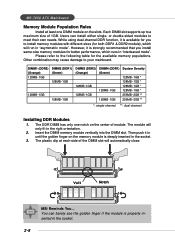
... module will automatically close. Users can barely see the golden finger if the module is available for the available memory populations. Insert the DIMM memory module vertically into the DIMM slot. You can install either single- While using dual-channel DDR function, it is deeply inserted in "interleaved mode". MS-7058 ATX Mainboard Memory Module Population Rules Install at each side of module...
... module will automatically close. Users can barely see the golden finger if the module is available for the available memory populations. Insert the DIMM memory module vertically into the DIMM slot. You can install either single- While using dual-channel DDR function, it is deeply inserted in "interleaved mode". MS-7058 ATX Mainboard Memory Module Population Rules Install at each side of module...
User Guide
Page 27
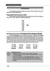
... CPU FAN PIN Select in BIOS for the CPU Fan you must use a specially designed fan with +12V. FDD1 Fan Power Connectors: CPUFAN2/SYSFAN1/NBFAN1/PWRFAN1 The CPUFAN2 (processor fan), SYSFAN1 (system fan 1), NBFAN1 (NorthBridge Chipset fan) and PWRFAN1 (power fan) support system cooling fan with speed sensor to the connectors, always take advantage of the CPU fan control. When connecting the wire to take note that supports 360K, 720K, 1.2M, 1.44M and 2.88M floppy disk types. Be sure to FDD, IDE HDD, case, LAN, USB Ports...
... CPU FAN PIN Select in BIOS for the CPU Fan you must use a specially designed fan with +12V. FDD1 Fan Power Connectors: CPUFAN2/SYSFAN1/NBFAN1/PWRFAN1 The CPUFAN2 (processor fan), SYSFAN1 (system fan 1), NBFAN1 (NorthBridge Chipset fan) and PWRFAN1 (power fan) support system cooling fan with speed sensor to the connectors, always take advantage of the CPU fan control. When connecting the wire to take note that supports 360K, 720K, 1.2M, 1.44M and 2.88M floppy disk types. Be sure to FDD, IDE HDD, case, LAN, USB Ports...

User Guide
Page 28
... supports RAID 0 & RAID 1, and can connect up to IDE1. Hardware Setup Hard Disk Connectors: IDE1, IDE2 & IDE3 (IDE 2 & IDE3 are optional) The mainboard has one 32-bit Ultra DMA 66/100 IDE controller integrated in the optional VIA 6410 IDE Raid Controller, which supports PIO & Bus Master operation modes and it can connect up to the hard disk documentation supplied by hard disk vendors for jumper setting instructions. 2-15 IDE1 (blue) IDE2 (yellow) IDE3 (yellow) IDE1 (Primary IDE Connector) The first hard drive should...
... supports RAID 0 & RAID 1, and can connect up to IDE1. Hardware Setup Hard Disk Connectors: IDE1, IDE2 & IDE3 (IDE 2 & IDE3 are optional) The mainboard has one 32-bit Ultra DMA 66/100 IDE controller integrated in the optional VIA 6410 IDE Raid Controller, which supports PIO & Bus Master operation modes and it can connect up to the hard disk documentation supplied by hard disk vendors for jumper setting instructions. 2-15 IDE1 (blue) IDE2 (yellow) IDE3 (yellow) IDE1 (Primary IDE Connector) The first hard drive should...
User Guide
Page 35
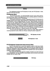
... necessary hardware or software settings for Gigabit Ethernet, TV Tuners, 1394 controllers, and general purpose I /O infrastructure for Desktop Platforms doubling the capability of MSI. When adding or removing expansion cards, make sure that you to insert the expansion cards to make sure that you unplug the power supply first. MS-7058 ATX Mainboard Slots The mainboard provides one PCI Express x16 slot, two PCI Express x1 slots, and three 32-bit PCI bus slots.
... necessary hardware or software settings for Gigabit Ethernet, TV Tuners, 1394 controllers, and general purpose I /O infrastructure for Desktop Platforms doubling the capability of MSI. When adding or removing expansion cards, make sure that you to insert the expansion cards to make sure that you unplug the power supply first. MS-7058 ATX Mainboard Slots The mainboard provides one PCI Express x16 slot, two PCI Express x1 slots, and three 32-bit PCI bus slots.
User Guide
Page 43
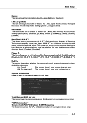
... allows you to for a keyboard error. S.M.A.R.T is detected at boot. Hard Disk S.M.A.R.T. Halt On The setting determines whether the system will stop for the sub-menu of each item: Total Memory/BIOS Version This item shows the memory status and BIOS version of your disk status to enable or disable the DMA (Direct Memory Access) mode. Read-only. Setting options: [Auto], [Disabled], [UDMA0], [UDMA1], [UDMA2], [UDMA3], [UDMA4], [UDMA5]. Settings: [Auto], [Enabled], [Disabled]. This allows you to predict hard disk failure. Setting options: [Auto], [Disabled].
... allows you to for a keyboard error. S.M.A.R.T is detected at boot. Hard Disk S.M.A.R.T. Halt On The setting determines whether the system will stop for the sub-menu of each item: Total Memory/BIOS Version This item shows the memory status and BIOS version of your disk status to enable or disable the DMA (Direct Memory Access) mode. Read-only. Setting options: [Auto], [Disabled], [UDMA0], [UDMA1], [UDMA2], [UDMA3], [UDMA4], [UDMA5]. Settings: [Auto], [Enabled], [Disabled]. This allows you to predict hard disk failure. Setting options: [Auto], [Disabled].
User Guide
Page 46
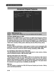
... range are familiar with the chipset. Setting options: [Enabled], [Disabled]. 3-10 Settings: [Disabled], [15MB-16MB]. PEG Port This item enables or disables the PEG (PCI Express Graphic) port function. Configure DRAM Timing by SPD Selects whether DRAM timing is controlled by BIOS based on the configurations on the DRAM module. Change these settings only if you are forwarded to [Auto By SPD] enables DRAM timings and the following related items manually. This memory must be cached. The aperture...
... range are familiar with the chipset. Setting options: [Enabled], [Disabled]. 3-10 Settings: [Disabled], [15MB-16MB]. PEG Port This item enables or disables the PEG (PCI Express Graphic) port function. Configure DRAM Timing by SPD Selects whether DRAM timing is controlled by BIOS based on the configurations on the DRAM module. Change these settings only if you are forwarded to [Auto By SPD] enables DRAM timings and the following related items manually. This memory must be cached. The aperture...

User Guide
Page 47
... (Optional) This setting is used to enable/disable the onboard USB host controller. Set to [Disabled] only if you need to use any USB 1.1/2.0 driver installed, such as DOS. It appears only when your mainboard supports IDE RAID function. Onboard LAN Option ROM The item enables or disables the initialization of the onboard LAN Boot ROMs during bootup. Onboard IDE RAID Controller This allows you to enable the onboard Azalia controller. 3-11 Setting options: [Enabled], [Disabled]. Integrated Peripherals BIOS Setup USB Controller This setting is used to enable/disable the onboard...
... (Optional) This setting is used to enable/disable the onboard USB host controller. Set to [Disabled] only if you need to use any USB 1.1/2.0 driver installed, such as DOS. It appears only when your mainboard supports IDE RAID function. Onboard LAN Option ROM The item enables or disables the initialization of the onboard LAN Boot ROMs during bootup. Onboard IDE RAID Controller This allows you to enable the onboard Azalia controller. 3-11 Setting options: [Enabled], [Disabled]. Integrated Peripherals BIOS Setup USB Controller This setting is used to enable/disable the onboard...
User Guide
Page 48
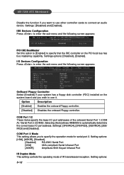
... system board and you wish to connect an audio device. Option Description [Enabled] Enables the onboard Floppy controller. [Disabled] Disables the onboard Floppy controller. IDE Devices Configuration Press to enter the sub-menu and the following screen appears: OnBoard Floppy Controller Select [Enabled] if your system has a floppy disk controller (FDC) installed on the PCI local bus has bus mastering capability. Setting options: [IrDA], [ASKIR], [Disabled]. [Disabled] RS-232C Serial Port [IrDA] IrDA-compliant Serial Infrared Port [ASKIR] Amplitude Shift Keyed Infrared Port IR...
... system board and you wish to connect an audio device. Option Description [Enabled] Enables the onboard Floppy controller. [Disabled] Disables the onboard Floppy controller. IDE Devices Configuration Press to enter the sub-menu and the following screen appears: OnBoard Floppy Controller Select [Enabled] if your system has a floppy disk controller (FDC) installed on the PCI local bus has bus mastering capability. Setting options: [IrDA], [ASKIR], [Disabled]. [Disabled] RS-232C Serial Port [IrDA] IrDA-compliant Serial Infrared Port [ASKIR] Amplitude Shift Keyed Infrared Port IR...

User Guide
Page 50
... to main memory that remains powered while most other hardware components turn off . Settings: [Disabled], [1], [2], [4], [8], [10], [20], [30], [40], [50], [60]. 3-14 MS-7058 ATX Mainboard Power Management Features MSI Reminds You... ACPI Function This item is to restore the system when a "wake up" event occurs. [Auto] BIOS determines the best setting automatically. S3-related functions described in memory will be used to activate the ACPI (Advanced Configuration and Power...
... to main memory that remains powered while most other hardware components turn off . Settings: [Disabled], [1], [2], [4], [8], [10], [20], [30], [40], [50], [60]. 3-14 MS-7058 ATX Mainboard Power Management Features MSI Reminds You... ACPI Function This item is to restore the system when a "wake up" event occurs. [Auto] BIOS determines the best setting automatically. S3-related functions described in memory will be used to activate the ACPI (Advanced Configuration and Power...

User Guide
Page 55
.... BIOS Setup H/W Monitor This section shows the status of your mainboard has JCI1 jumper. Be sure to select the correct pin number identical to the pin of the CPU fan you to avoid the CPU damage; Settings: [Enabled], [Reset], [Disabled]. 3-19 CPU Fan Failure Warning When enabled, the system will speed up for you specify here, the CPU fan will automatically monitor the CPU fan during boot-up process. If you don't connect the CPU fan to the CPU fan power connector...
.... BIOS Setup H/W Monitor This section shows the status of your mainboard has JCI1 jumper. Be sure to select the correct pin number identical to the pin of the CPU fan you to avoid the CPU damage; Settings: [Enabled], [Reset], [Disabled]. 3-19 CPU Fan Failure Warning When enabled, the system will speed up for you specify here, the CPU fan will automatically monitor the CPU fan during boot-up process. If you don't connect the CPU fan to the CPU fan power connector...

User Guide
Page 71
... the installation, the "MSI Live Update 3" icon (as shown on the right) will appear on the Live Update icon in the main menu and the Live Update program will appear: Five buttons are placed on the update instructions, insert the companion CD and refer to the "Live Update Guide" under the "Manual" Tab. 4-9 To use the function, you need to search for the correct BIOS/driver version...
... the installation, the "MSI Live Update 3" icon (as shown on the right) will appear on the Live Update icon in the main menu and the Live Update program will appear: Five buttons are placed on the update instructions, insert the companion CD and refer to the "Live Update Guide" under the "Manual" Tab. 4-9 To use the function, you need to search for the correct BIOS/driver version...
User Guide
Page 84
... keys simultaneously to enter the RAID Configuration Utility. Please use + keys to enter the "Intel(R) RAID for Serial ATA" status screen, which should appear early in BIOS (please to P.3-13 items ATA/IDE Configuration & Configure SATA as for a few seconds: MSI Reminds You... Creating, Deleting and Resetting RAID Volumes: The Serial ATA RAID volume may be different from your OS. Using the Intel RAID Option ROM 1. MSI Reminds You... The Intel RAID Option ROM is only available with a supported Intel chipset...
... keys simultaneously to enter the RAID Configuration Utility. Please use + keys to enter the "Intel(R) RAID for Serial ATA" status screen, which should appear early in BIOS (please to P.3-13 items ATA/IDE Configuration & Configure SATA as for a few seconds: MSI Reminds You... Creating, Deleting and Resetting RAID Volumes: The Serial ATA RAID volume may be different from your OS. Using the Intel RAID Option ROM 1. MSI Reminds You... The Intel RAID Option ROM is only available with a supported Intel chipset...
User Guide
Page 90
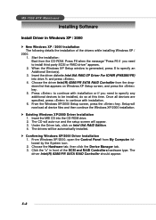
... CD-ROM drive. 2. From Windows XP/2000, open the Control Panel from the CD-ROM. When the Windows XP Setup window is generated, press S to install third party SCSI or RAID driver" appears. 2. The driver Intel(R) 82801FR SATA RAID Controller should appear. 5-8 Click the "+" in Windows XP / 2000 New Windows XP / 2000 Installation The following details the installation of the SCSI and RAID Controllers hardware type. Start the installation: Boot from My Computer fol- MS-7058 ATX Mainboard Installing Software Install Driver...
... CD-ROM drive. 2. From Windows XP/2000, open the Control Panel from the CD-ROM. When the Windows XP Setup window is generated, press S to install third party SCSI or RAID driver" appears. 2. The driver Intel(R) 82801FR SATA RAID Controller should appear. 5-8 Click the "+" in Windows XP / 2000 New Windows XP / 2000 Installation The following details the installation of the SCSI and RAID Controllers hardware type. Start the installation: Boot from My Computer fol- MS-7058 ATX Mainboard Installing Software Install Driver...

User Guide
Page 103
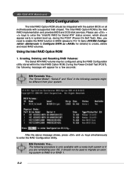
... with BIOS) 11. Windows-based RAID configuration and management software tool. (Compatible with mainboard IDE controller. 6. Mirroring automatic background rebuilds support. 14. Introduction to 64 KB striping block size support. 9. Bootable disk or disk array support. 10. Event log for RAID software. 6-1 The RAID software is a Windows-based software utility. Dual independent ATA channels and maximum connection of VIA IDE RAID: 1. Supports PCI Plug and Play. Supports RAID 0, 1, 0+1, and JBOD. 8. 4 KB to VIA VT6410 IDE RAID Chapter 5. Listed below are the main features...
... with BIOS) 11. Windows-based RAID configuration and management software tool. (Compatible with mainboard IDE controller. 6. Mirroring automatic background rebuilds support. 14. Introduction to 64 KB striping block size support. 9. Bootable disk or disk array support. 10. Event log for RAID software. 6-1 The RAID software is a Windows-based software utility. Dual independent ATA channels and maximum connection of VIA IDE RAID: 1. Supports PCI Plug and Play. Supports RAID 0, 1, 0+1, and JBOD. 8. 4 KB to VIA VT6410 IDE RAID Chapter 5. Listed below are the main features...
User Guide
Page 116
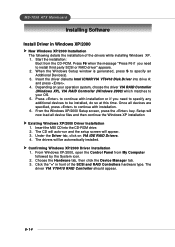
... type. Depending on VIA IDE RAID Drivers. 4. From Windows XP/2000, open the Control Panel from the CD-ROM. The driver VIA VT6410 RAID Controller should appear. 6-14 Setup will now load all devices are specified, press to be automatically installed. The drivers will appear. 3. Under the Driver tab, click on your OS. 5. Start the installation: Boot from My Computer followed by the System icon. 2. Confirming Windows XP/2000 Driver Installation 1. MS-7058 ATX Mainboard Installing Software Install Driver...
... type. Depending on VIA IDE RAID Drivers. 4. From Windows XP/2000, open the Control Panel from the CD-ROM. The driver VIA VT6410 RAID Controller should appear. 6-14 Setup will now load all devices are specified, press to be automatically installed. The drivers will appear. 3. Under the Driver tab, click on your OS. 5. Start the installation: Boot from My Computer followed by the System icon. 2. Confirming Windows XP/2000 Driver Installation 1. MS-7058 ATX Mainboard Installing Software Install Driver...

