User Guide
Page 8
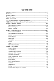
... ...2-11 Button ...2-19 Slots ...2-22 LED Status Indicators 2-26 Chapter 3 BIOS Setup 3-1 Entering Setup ...3-2 The Main Menu ...3-4 Standard CMOS Features 3-6 Advanced BIOS Features 3-8 Integrated Peripherals 3-11 Power Management Setup 3-13 H/W Monitor ...3-16 Green Power ...3-17 BIOS Setting Password 3-18 Cell Menu ...3-19 User Setting ...3-26 M-Flash ...3-27 Load Fail-Safe/ Optimized Defaults 3-30 CONTENTS Copyright...
... ...2-11 Button ...2-19 Slots ...2-22 LED Status Indicators 2-26 Chapter 3 BIOS Setup 3-1 Entering Setup ...3-2 The Main Menu ...3-4 Standard CMOS Features 3-6 Advanced BIOS Features 3-8 Integrated Peripherals 3-11 Power Management Setup 3-13 H/W Monitor ...3-16 Green Power ...3-17 BIOS Setting Password 3-18 Cell Menu ...3-19 User Setting ...3-26 M-Flash ...3-27 Load Fail-Safe/ Optimized Defaults 3-30 CONTENTS Copyright...
User Guide
Page 26
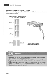
... SATA7 SATA7 & SATA8 are controlled by JMB322 Important 1. SATA7 & SATA8 support RAID 0/ RAID 1/ JBOD function and you can connect to the BIOS section or Appendix section). 2-12 MS-7577 Mainboard Serial ATA Connector: SATA1~ SATA8 This connector is a high-speed Serial ATA interface port. Each... connector can set RAID mode in BIOS setup or in DRIVE BOOSTER MANAGER (refer to one Serial ATA device. Please always use the AM D default Black SATA connectors (...
... SATA7 SATA7 & SATA8 are controlled by JMB322 Important 1. SATA7 & SATA8 support RAID 0/ RAID 1/ JBOD function and you can connect to the BIOS section or Appendix section). 2-12 MS-7577 Mainboard Serial ATA Connector: SATA1~ SATA8 This connector is a high-speed Serial ATA interface port. Each... connector can set RAID mode in BIOS setup or in DRIVE BOOSTER MANAGER (refer to one Serial ATA device. Please always use the AM D default Black SATA connectors (...
User Guide
Page 27
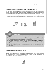
...system cooling fan with 3 or 4 pins power connector are both available for proper CPU cooling fan. 2. Fan cooler set with +12V. W hen connecting the wire to the connectors, always note that will automatically control the CPU fan speed... consult the vendors for CPUFAN1. GND CINTRU 2 1 2-13 To clear the warning, you must enter the BIOS utility and clear the record. GND +1 2V SE NS OR CONTROL SE NS OR +1 2V GND CPUFAN1 ... positive and should be connected to GND. If the motherboard has a System Hardware Monitor chipset on the screen. CPUFAN1 supports fan control.
...system cooling fan with 3 or 4 pins power connector are both available for proper CPU cooling fan. 2. Fan cooler set with +12V. W hen connecting the wire to the connectors, always note that will automatically control the CPU fan speed... consult the vendors for CPUFAN1. GND CINTRU 2 1 2-13 To clear the warning, you must enter the BIOS utility and clear the record. GND +1 2V SE NS OR CONTROL SE NS OR +1 2V GND CPUFAN1 ... positive and should be connected to GND. If the motherboard has a System Hardware Monitor chipset on the screen. CPUFAN1 supports fan control.
User Guide
Page 34
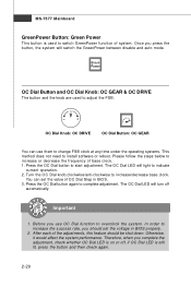
... software or reboot. You can use OC Dial function to complete adjustment. OC Dial Knob: OC DRIVE OC Dial Button: OC GEAR You can set the voltage in BIOS. 3. Before you should be shut down. OC Dial Button and OC Dial Knob: OC GEAR & OC DRIVE The button and the knob are... used to start adjustment. After each of the adjustments, this feature should set the value of system. Press the OC Dial button again to overclock the...
... software or reboot. You can use OC Dial function to complete adjustment. OC Dial Knob: OC DRIVE OC Dial Button: OC GEAR You can set the voltage in BIOS. 3. Before you should be shut down. OC Dial Button and OC Dial Knob: OC GEAR & OC DRIVE The button and the knob are... used to start adjustment. After each of the adjustments, this feature should set the value of system. Press the OC Dial button again to overclock the...
User Guide
Page 36
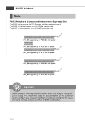
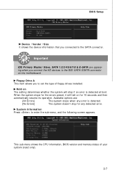
... supports up to PCIE 2.0 x8 speed PCI_E4 supports up to PCIE 2.0 x16 speed PCI_E5 supports up to configure any necessary hardware or software settings for the expansion card to 8.0 GB/s transfer rate. Meanwhile, read the documentation for the expansion card, such as jumpers, switches or... BIOS configuration. 2-22 The PCIE x16 slots support up to 250 MB/s transfer rate. MS-7577 Mainboard Slots PCIE (Peripheral Component Interconnect Express) Slot ...
... supports up to PCIE 2.0 x8 speed PCI_E4 supports up to PCIE 2.0 x16 speed PCI_E5 supports up to configure any necessary hardware or software settings for the expansion card to 8.0 GB/s transfer rate. Meanwhile, read the documentation for the expansion card, such as jumpers, switches or... BIOS configuration. 2-22 The PCIE x16 slots support up to 250 MB/s transfer rate. MS-7577 Mainboard Slots PCIE (Peripheral Component Interconnect Express) Slot ...
User Guide
Page 39
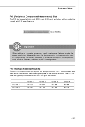
The PCI IRQ pins are hardware lines over which devices can send interrupt signals to configure any necessary hardware or software settings for the expansion card to the microprocessor. Hardware Setup PCI (Peripheral Component Interconnect) Slot The PCI slot supports LAN card, SCSI card, USB card, and ... PCI Interrupt Request Routing The IRQ, acronym of interrupt request line and pronounced I-R-Q, are typically connected to the PCI bus pins as jumpers, switches or BIOS configuration.
The PCI IRQ pins are hardware lines over which devices can send interrupt signals to configure any necessary hardware or software settings for the expansion card to the microprocessor. Hardware Setup PCI (Peripheral Component Interconnect) Slot The PCI slot supports LAN card, SCSI card, USB card, and ... PCI Interrupt Request Routing The IRQ, acronym of interrupt request line and pronounced I-R-Q, are typically connected to the PCI bus pins as jumpers, switches or BIOS configuration.

User Guide
Page 42
Chapter 3 BIOS Setup BIOS Setup This chapter provides information on the BIOS Setup program and allows you to run the Setup program when: ² An error message appears on the screen during the system booting up, and requests you to change the default settings for optimum use. You may need to run SETUP. ² You want to configure the system for customized features. 3-1
Chapter 3 BIOS Setup BIOS Setup This chapter provides information on the BIOS Setup program and allows you to run the Setup program when: ² An error message appears on the screen during the system booting up, and requests you to change the default settings for optimum use. You may need to run SETUP. ² You want to configure the system for customized features. 3-1
User Guide
Page 45
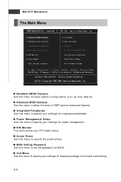
... for frequency/voltage control and overclocking. 3-4 Integrated Peripherals Use this menu to specify your settings for basic system configurations, such as time, date etc. H/W Monitor This entry shows your settings for BIOS. Cell Menu Use this menu to set the password for integrated peripherals. BIOS Setting Password Use this menu to specify your PC health status.
... for frequency/voltage control and overclocking. 3-4 Integrated Peripherals Use this menu to specify your settings for basic system configurations, such as time, date etc. H/W Monitor This entry shows your settings for BIOS. Cell Menu Use this menu to set the password for integrated peripherals. BIOS Setting Password Use this menu to specify your PC health status.
User Guide
Page 46
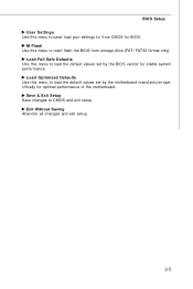
Exit Without Saving Abandon all changes and exit setup. 3-5 Save & Exit Setup Save changes to / from storage drive (FAT/ FAT32 format only). BIOS Setup User Settings Use this menu to save/ load your settings to CMOS and exit setup. M-Flash Use this menu to load the default values set by the motherboard manufacturer specifically for stable system performance. Load Optimized Defaults Use this menu to load the default values set by the BIOS vendor for optimal performance of the motherboard. Load Fail-Safe Defaults Use this menu to read/ flash the BIOS from CMOS for BIOS.
Exit Without Saving Abandon all changes and exit setup. 3-5 Save & Exit Setup Save changes to / from storage drive (FAT/ FAT32 format only). BIOS Setup User Settings Use this menu to save/ load your settings to CMOS and exit setup. M-Flash Use this menu to load the default values set by the motherboard manufacturer specifically for stable system performance. Load Optimized Defaults Use this menu to load the default values set by the BIOS vendor for optimal performance of the motherboard. Load Fail-Safe Defaults Use this menu to read/ flash the BIOS from CMOS for BIOS.
User Guide
Page 47
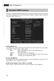
year The year can be adjusted by users. Date (MM:DD:YY) This allows you to set the system time that you want (usually the current time). through Dec. The time format is . IDE Primary Master/ Slave, SATA1~8, E-SATA Press to enter ..., and the following screen appears. 3-6 date The date from 1 to 31 can be keyed by BIOS. Read-only. The format is . day Day of the week, from Jan. Time (HH:MM :SS) This allows you to set the system to the date that you want in Standard CMOS Features Menu include some...
year The year can be adjusted by users. Date (MM:DD:YY) This allows you to set the system time that you want (usually the current time). through Dec. The time format is . IDE Primary Master/ Slave, SATA1~8, E-SATA Press to enter ..., and the following screen appears. 3-6 date The date from 1 to 31 can be keyed by BIOS. Read-only. The format is . day Day of the week, from Jan. Time (HH:MM :SS) This allows you to set the system to the date that you want in Standard CMOS Features Menu include some...
User Guide
Page 48
...for the errors preset, it will stop for 15 seconds and then automatically resume its operation. Hold on The setting determines whether the system will halt on the motherboard. BIOS Setup Device / Vender / Size It shows the device information that you connect the HD devices to the IDE.../ SATA/ ESATA connector on for any error is detected at boot. System Information Press to set the type of your system (read...
...for the errors preset, it will stop for 15 seconds and then automatically resume its operation. Hold on The setting determines whether the system will halt on the motherboard. BIOS Setup Device / Vender / Size It shows the device information that you connect the HD devices to the IDE.../ SATA/ ESATA connector on for any error is detected at boot. System Information Press to set the type of your system (read...
User Guide
Page 49
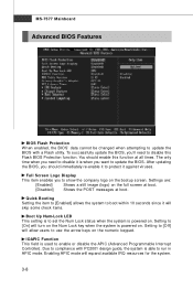
... skip some check items. Boot Up Num-Lock LED This setting is to set the Num Lock status when the system is powered on the bootup screen. After updating the BIOS, you should enable this Flash BIOS Protection function. Setting to [Off] will turn on the Num Lock key when...with a Flash utility. Settings are: [Enabled] Shows a still image (logo) on the full screen at boot. [Disabled] Shows the POST messages at all times. The only time when you want to update the BIOS. MS-7577 Mainboard Advanced BIOS Features BIOS Flash Protection W hen enabled, the BIOS' data cannot be ...
... skip some check items. Boot Up Num-Lock LED This setting is to set the Num Lock status when the system is powered on the bootup screen. After updating the BIOS, you should enable this Flash BIOS Protection function. Setting to [Off] will turn on the Num Lock key when...with a Flash utility. Settings are: [Enabled] Shows a still image (logo) on the full screen at boot. [Disabled] Shows the POST messages at all times. The only time when you want to update the BIOS. MS-7577 Mainboard Advanced BIOS Features BIOS Flash Protection W hen enabled, the BIOS' data cannot be ...
User Guide
Page 50
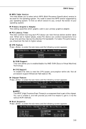
... adapter. To find out which MPS (Multi-Processor Specification) version to be used for a longer time and thus improve the effective PCI bandwidth. W hen set the item to higher values. C1E Support To enable this item to select the MPS version supported by your operating system. Boot Sequence Press to...-menu and the following screen appears: SVM Support This item allows you to enable/disable the AMD SVM (Secure Virtual Machine) Tec hn ology. BIOS Setup MPS Table Version This field allows you to select which version to use, consult the vendor of the chipset. You need to read the...
... adapter. To find out which MPS (Multi-Processor Specification) version to be used for a longer time and thus improve the effective PCI bandwidth. W hen set the item to higher values. C1E Support To enable this item to select the MPS version supported by your operating system. Boot Sequence Press to...-menu and the following screen appears: SVM Support This item allows you to enable/disable the AMD SVM (Secure Virtual Machine) Tec hn ology. BIOS Setup MPS Table Version This field allows you to select which version to use, consult the vendor of the chipset. You need to read the...
User Guide
Page 51
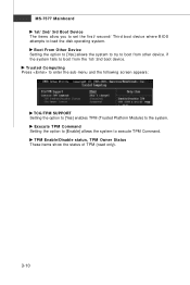
...10 Trusted Computing Press to enter the sub-menu and the following screen appears: TCG/TPM SUPPORT Setting the option to [Yes] enables TPM (Trusted Platform Module) to execute TPM Command. Boot From Other Device Setting the option to [Yes] allows the system to try to load the disk operating system. ...MS-7577 Mainboard 1st/ 2nd/ 3rd Boot Device The items allow you to set the first/ second/ Third boot device where BIOS attempts to boot from the 1st/ ...
...10 Trusted Computing Press to enter the sub-menu and the following screen appears: TCG/TPM SUPPORT Setting the option to [Yes] enables TPM (Trusted Platform Module) to execute TPM Command. Boot From Other Device Setting the option to [Yes] allows the system to try to load the disk operating system. ...MS-7577 Mainboard 1st/ 2nd/ 3rd Boot Device The items allow you to set the first/ second/ Third boot device where BIOS attempts to boot from the 1st/ ...
User Guide
Page 52
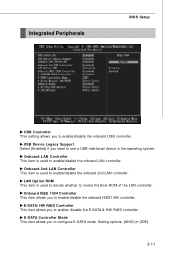
LAN Option ROM This item is used to enable/disable the onboard 2nd LAN controller. Setting options: [AHCI] or [IDE]. 3-11 USB Device Legacy Support Select [Enabled] if you need to enable/ disable the E-SATA & HW RAID controller. E-SATA/ HW RAID ... enable/disable the onboard USB controller. Onboard 2nd LAN Controller This item is used to decide whether to configure E-SATA mode. Integrated Peripherals BIOS Setup USB Controller This setting allows you to enable/disable the onboard IEEE1394 controller. E-SATA Controller Mode This item allows you to invoke the Boot ROM of the...
LAN Option ROM This item is used to enable/disable the onboard 2nd LAN controller. Setting options: [AHCI] or [IDE]. 3-11 USB Device Legacy Support Select [Enabled] if you need to enable/ disable the E-SATA & HW RAID controller. E-SATA/ HW RAID ... enable/disable the onboard USB controller. Onboard 2nd LAN Controller This item is used to decide whether to configure E-SATA mode. Integrated Peripherals BIOS Setup USB Controller This setting allows you to enable/disable the onboard IEEE1394 controller. E-SATA Controller Mode This item allows you to invoke the Boot ROM of the...
User Guide
Page 53
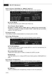
...menu and the following screen appears: PCI IDE BusMaster This item allows you to enable or disable the SATA controller. Onboard Audio This setting is used to IDE drives. Setting options: [RAID],[AHCI] or [IDE]. I/O Device Configuration Press to enter the sub-menu, and the following screen appears. MS... for the first serial port. 3-12 Current Mode This item shows the current SATA mode. RAID Mode This item allows you to enable/ disable BIOS to used to enable the RAID0/ RAID1/ JBOD/ Normal (non-RAID) mode for reading/ writing to enable/disable the onboard audio controller. Read...
...menu and the following screen appears: PCI IDE BusMaster This item allows you to enable or disable the SATA controller. Onboard Audio This setting is used to IDE drives. Setting options: [RAID],[AHCI] or [IDE]. I/O Device Configuration Press to enter the sub-menu, and the following screen appears. MS... for the first serial port. 3-12 Current Mode This item shows the current SATA mode. RAID Mode This item allows you to enable/ disable BIOS to used to enable the RAID0/ RAID1/ JBOD/ Normal (non-RAID) mode for reading/ writing to enable/disable the onboard audio controller. Read...
User Guide
Page 54
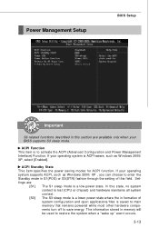
...modes for ACPI function. The information stored in memory will be used to activate the ACPI (Advanced Configuration and Power Management Interface) Function. If your BIOS supports S3 sleep mode. In this state, no system context is lost (CPU or chipset) and hardware maintains all system context. [S3] The ... in this field. ACPI Function This item is saved to main memory that remains powered while most other hardware components turn off to save energy. Settings are available only when your operating system is ACPI-aware, such as W indows 2000/ XP , you can choose to enter the Standby mode ...
...modes for ACPI function. The information stored in memory will be used to activate the ACPI (Advanced Configuration and Power Management Interface) Function. If your BIOS supports S3 sleep mode. In this state, no system context is lost (CPU or chipset) and hardware maintains all system context. [S3] The ... in this field. ACPI Function This item is saved to main memory that remains powered while most other hardware components turn off to save energy. Settings are available only when your operating system is ACPI-aware, such as W indows 2000/ XP , you can choose to enter the Standby mode ...

User Guide
Page 55
...to RAM) sleep state. Wake Up Event Setup Press and the following sub-menu appears. Resume From S3 By PS/2 Keyboard/ Mouse This setting determines whether the system will be awakened from S3 (Suspend to the status before power failure or interrupt occurred. Restore On AC Power Loss ...activity of the power button. Resume By PCI Device (PM E#) W hen set to select the indication method of Power LED. Power Button Function This feature sets the function of the USB device to wake up event by BIOS or OS. Settings are : [OFF] Always leaves the computer in the power off state....
...to RAM) sleep state. Wake Up Event Setup Press and the following sub-menu appears. Resume From S3 By PS/2 Keyboard/ Mouse This setting determines whether the system will be awakened from S3 (Suspend to the status before power failure or interrupt occurred. Restore On AC Power Loss ...activity of the power button. Resume By PCI Device (PM E#) W hen set to select the indication method of Power LED. Power Button Function This feature sets the function of the USB device to wake up event by BIOS or OS. Settings are : [OFF] Always leaves the computer in the power off state....
User Guide
Page 59
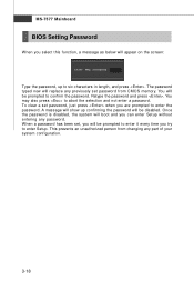
..., just press when you are prompted to abort the selection and not enter a password. W hen a password has been set password from changing any part of your system configuration. 3-18 This prevents an unauthorized person from CMOS memory. You may also press to .... The password typed now will replace any password. Once the password is disabled, the system will be prompted to confirm the password. MS-7577 Mainboard BIOS Setting Password W hen you select this function, a message as below will appear on the screen: Type the password, up confirming the password will be prompted...
..., just press when you are prompted to abort the selection and not enter a password. W hen a password has been set password from changing any part of your system configuration. 3-18 This prevents an unauthorized person from CMOS memory. You may also press to .... The password typed now will replace any password. Once the password is disabled, the system will be prompted to confirm the password. MS-7577 Mainboard BIOS Setting Password W hen you select this function, a message as below will appear on the screen: Type the password, up confirming the password will be prompted...
User Guide
Page 71
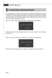
... below appears: Pressing Y loads the default factory settings for optimal performance of the BIOS settings to restore all of the motherboard. The Fail-Safe Defaults are the default values set by the motherboard manufacturer specifically for optimal system performance. 3-30 The Optimized Defaults are the default values set by the BIOS vendor for the most stable, minimal system...
... below appears: Pressing Y loads the default factory settings for optimal performance of the BIOS settings to restore all of the motherboard. The Fail-Safe Defaults are the default values set by the motherboard manufacturer specifically for optimal system performance. 3-30 The Optimized Defaults are the default values set by the BIOS vendor for the most stable, minimal system...

