User Guide
Page 2
...; JMicron® is registered trademark of JMicron Technology Corporation. ■ Netware® is the intellectual property of MICRO-STAR INTERNATIONAL. Alternatively, please try the following help resources for further guidance. ◙ Visit the MSI website for FAQ, technical guide, BIOS updates, driver updates, and other information: http://www.msi.com/index.php?func=service ◙ Contact our technical staff at...
...; JMicron® is registered trademark of JMicron Technology Corporation. ■ Netware® is the intellectual property of MICRO-STAR INTERNATIONAL. Alternatively, please try the following help resources for further guidance. ◙ Visit the MSI website for FAQ, technical guide, BIOS updates, driver updates, and other information: http://www.msi.com/index.php?func=service ◙ Contact our technical staff at...
User Guide
Page 8
... History ii Technical Support ii Safety Instructions iii FCC-B Radio Frequency Interference Statement iv WEEE (Waste Electrical and Electronic Equipment) Statement v Chapter 1 Getting Started 1-1 Mainboard Specifications 1-2 Mainboard Layout 1-4 Packing Checklist 1-5 Chapter 2 Hardware Setup 2-1 Quick Components Guide 2-2 CPU (Central Processing Unit 2-3 Memory 2-6 Power Supply 2-8 Back Panel 2-9 Connectors 2-11 Jumpers 2-17 Switch 2-18 Slots 2-19 LED Status Indicators 2-20 Chapter 3 BIOS Setup 3-1 Entering Setup 3-2 The Main Menu 3-4 Standard CMOS Features 3-6 Advanced...
... History ii Technical Support ii Safety Instructions iii FCC-B Radio Frequency Interference Statement iv WEEE (Waste Electrical and Electronic Equipment) Statement v Chapter 1 Getting Started 1-1 Mainboard Specifications 1-2 Mainboard Layout 1-4 Packing Checklist 1-5 Chapter 2 Hardware Setup 2-1 Quick Components Guide 2-2 CPU (Central Processing Unit 2-3 Memory 2-6 Power Supply 2-8 Back Panel 2-9 Connectors 2-11 Jumpers 2-17 Switch 2-18 Slots 2-19 LED Status Indicators 2-20 Chapter 3 BIOS Setup 3-1 Entering Setup 3-2 The Main Menu 3-4 Standard CMOS Features 3-6 Advanced...

User Guide
Page 24
....GVround ATX 4-pin Power Connector: JPWR2 This power connector is used to provide power to the CPU. 2.G1.rGouronudnd 4.+31.+21V2V Important • Make sure that all the connectors are aligned. If you'd like . Then push down the power supply firmly into the connector. To connect the ATX 24-pin power supply, make sure the plug of 350 watts (and above) is highly recommended for system stability. 2-8 ▍ Hardware Setup Power Supply ATX 24-pin Power Connector...
....GVround ATX 4-pin Power Connector: JPWR2 This power connector is used to provide power to the CPU. 2.G1.rGouronudnd 4.+31.+21V2V Important • Make sure that all the connectors are aligned. If you'd like . Then push down the power supply firmly into the connector. To connect the ATX 24-pin power supply, make sure the plug of 350 watts (and above) is highly recommended for system stability. 2-8 ▍ Hardware Setup Power Supply ATX 24-pin Power Connector...

User Guide
Page 25
...; VGA Port The DB15-pin female connector is provided for attaching USB devices such as keyboard, mouse, or other end of the cable is properly connected to your monitor (refer to your monitor manual for more information.) ▶ HDMI Port The High-Definition Multimedia Interface (HDMI) is an all-digital audio/video interface capable of transmitting uncompressed streams. HDMI supports all TV format, including standard, enhanced, or high-definition video, plus multi-channel...
...; VGA Port The DB15-pin female connector is provided for attaching USB devices such as keyboard, mouse, or other end of the cable is properly connected to your monitor (refer to your monitor manual for more information.) ▶ HDMI Port The High-Definition Multimedia Interface (HDMI) is an all-digital audio/video interface capable of transmitting uncompressed streams. HDMI supports all TV format, including standard, enhanced, or high-definition video, plus multi-channel...

User Guide
Page 27
...-ddkdfdfldkddj adfdsdddjdfddf fkadadsf dddffdfadasfadfsddsddadasdsaddsdafsddadsdddfdsadddffffafsfsdafsdf ff df 3 1/2" Fl oppy Disk Dr i veConnector CD-RMOSMI Kdkldkddfkkakfskkdskkdakaddfdddffdfkadd-kdffdldkddjdafdsdddjdfddfdfkaadsfdddffdfadasfsadfddsddadasdsaddsdafsddadsdddfdsadddfffaffsfsdasfdfffdf 3 1/2" F loppy Di sk D r ive Connector Important If you install two IDE devices on the same cable, you must configure the drives separately to IDE device's documentation supplied by setting jumpers. Refer to master / slave mode by the vendors for jumper setting instructions. 2-11
...-ddkdfdfldkddj adfdsdddjdfddf fkadadsf dddffdfadasfadfsddsddadasdsaddsdafsddadsdddfdsadddffffafsfsdafsdf ff df 3 1/2" Fl oppy Disk Dr i veConnector CD-RMOSMI Kdkldkddfkkakfskkdskkdakaddfdddffdfkadd-kdffdldkddjdafdsdddjdfddfdfkaadsfdddffdfadasfsadfddsddadasdsaddsdafsddadsdddfdsadddfffaffsfsdasfdfffdf 3 1/2" F loppy Di sk D r ive Connector Important If you install two IDE devices on the same cable, you must configure the drives separately to IDE device's documentation supplied by setting jumpers. Refer to master / slave mode by the vendors for jumper setting instructions. 2-11

User Guide
Page 28
... fan power connectors support system cooling fan with 3 or 4 pins power connector are both available for proper CPU cooling fan. • CPUFAN1 supports fan control. Otherwise, data loss may select how percentage of the CPU fan control. If the mainboard has a System Hardware Monitor chipset on-board, you must use a specially designed fan with speed sensor to the recommended CPU fans at processor's official website or consult the vendors for CPUFAN1. • SYSFAN1 support fan control, too. When connecting the wire...
... fan power connectors support system cooling fan with 3 or 4 pins power connector are both available for proper CPU cooling fan. • CPUFAN1 supports fan control. Otherwise, data loss may select how percentage of the CPU fan control. If the mainboard has a System Hardware Monitor chipset on-board, you must use a specially designed fan with speed sensor to the recommended CPU fans at processor's official website or consult the vendors for CPUFAN1. • SYSFAN1 support fan control, too. When connecting the wire...

User Guide
Page 33
If you want to clear the system configuration, set the jumper to clear data. 1 JCMOS 1 Keep Data 1 Clear Data Important You can automatically boot OS every time it will damage the mainboard. 2-17 it is turned on ; Then return to keep the data of system configuration. Avoid clearing the CMOS while the system is on . With the CMOS RAM, the system can clear CMOS by shorting 2-3 pin while the system is off. MS-7549 Jumpers Clear CMOS Jumper: JBAT1 There is a CMOS RAM onboard that has a power supply from an external battery to 1-2 pin position.
If you want to clear the system configuration, set the jumper to clear data. 1 JCMOS 1 Keep Data 1 Clear Data Important You can automatically boot OS every time it will damage the mainboard. 2-17 it is turned on ; Then return to keep the data of system configuration. Avoid clearing the CMOS while the system is on . With the CMOS RAM, the system can clear CMOS by shorting 2-3 pin while the system is off. MS-7549 Jumpers Clear CMOS Jumper: JBAT1 There is a CMOS RAM onboard that has a power supply from an external battery to 1-2 pin position.

User Guide
Page 35
... Slots PCI (Peripheral Component Interconnect) Express Slot The PCI Express slot supports the PCI Express interface expansion card. PCI Express x16 Slot PCI Express x1 Slot PCI (Peripheral Component Interconnect) Slot The PCI slot supports LAN card, SCSI card, USB card, and other add-on cards that comply with PCI specifications. 32-bit PCI Slot Important When adding or removing expansion cards, make sure that you unplug the power supply first. The PCI IRQ pins are hardware lines over which devices can send interrupt signals to configure any necessary hardware or software settings...
... Slots PCI (Peripheral Component Interconnect) Express Slot The PCI Express slot supports the PCI Express interface expansion card. PCI Express x16 Slot PCI Express x1 Slot PCI (Peripheral Component Interconnect) Slot The PCI slot supports LAN card, SCSI card, USB card, and other add-on cards that comply with PCI specifications. 32-bit PCI Slot Important When adding or removing expansion cards, make sure that you unplug the power supply first. The PCI IRQ pins are hardware lines over which devices can send interrupt signals to configure any necessary hardware or software settings...

User Guide
Page 43
... Technology) capability for the hard disks. S.M.A.R.T is a utility that monitors your system (read only). 3-7 This sub-menu shows the CPU information, BIOS version and memory status of your disk status to predict hard disk failure. This allows you an opportunity to move data from a hard disk that is not already formatted with LBA mode disabled. ▶ DMA Mode Select DMA Mode. ▶ Hard Disk S.M.A.R.T. Setting to enable or disable the LBA Mode. MS-7549 ▶ Device / Vendor / Size...
... Technology) capability for the hard disks. S.M.A.R.T is a utility that monitors your system (read only). 3-7 This sub-menu shows the CPU information, BIOS version and memory status of your disk status to predict hard disk failure. This allows you an opportunity to move data from a hard disk that is not already formatted with LBA mode disabled. ▶ DMA Mode Select DMA Mode. ▶ Hard Disk S.M.A.R.T. Setting to enable or disable the LBA Mode. MS-7549 ▶ Device / Vendor / Size...

User Guide
Page 44
... screen at boot. [Disabled] Shows the POST messages at boot. ▶ Quick Booting Setting the item to [Enabled] allows the system to boot within 10 seconds since it will alarm beep. ▶ Full Screen Logo Display This item enables this area, BIOS will show the company logo on the boot-up screen. Setting to enable or disable the APIC (Advanced Programmable Interrupt Controller). Setting to [Off] will allow users to use the arrow keys...
... screen at boot. [Disabled] Shows the POST messages at boot. ▶ Quick Booting Setting the item to [Enabled] allows the system to boot within 10 seconds since it will alarm beep. ▶ Full Screen Logo Display This item enables this area, BIOS will show the company logo on the boot-up screen. Setting to enable or disable the APIC (Advanced Programmable Interrupt Controller). Setting to [Off] will allow users to use the arrow keys...

User Guide
Page 45
..., multimonitor support for computers that is your operating system. This setting controls the exact memory size shared to it will provide you with ATI integrated graphics processors (IGPs). 3-9 To find out which version to use an PCI Express based graphics card in conjunction with the means to get to the VGA card. ▶ Surround View SURROUNDVIEW provides the power and convenience of the chipset. You can enable it...
..., multimonitor support for computers that is your operating system. This setting controls the exact memory size shared to it will provide you with ATI integrated graphics processors (IGPs). 3-9 To find out which version to use an PCI Express based graphics card in conjunction with the means to get to the VGA card. ▶ Surround View SURROUNDVIEW provides the power and convenience of the chipset. You can enable it...

User Guide
Page 47
... to enable/disable the onboard USB controller. ▶ USB Device Legacy Support Select [Enabled] if you need to use a USB-interfaced device in the operating system. ▶ Onboard LAN Controller This item is used to enable/disable the onboard 1st LAN controller. ▶ LAN Option ROM This item is used to decide whether to invoke the Boot ROM of the LAN controller. ▶ HD Audio Controller This setting is used to enable/disable the onboard audio controller. ▶ On-Chip ATA Devices Press to enter the sub-menu and the following screen appears: ▶ PCI IDE...
... to enable/disable the onboard USB controller. ▶ USB Device Legacy Support Select [Enabled] if you need to use a USB-interfaced device in the operating system. ▶ Onboard LAN Controller This item is used to enable/disable the onboard 1st LAN controller. ▶ LAN Option ROM This item is used to decide whether to invoke the Boot ROM of the LAN controller. ▶ HD Audio Controller This setting is used to enable/disable the onboard audio controller. ▶ On-Chip ATA Devices Press to enter the sub-menu and the following screen appears: ▶ PCI IDE...

User Guide
Page 49
... a "wake up" event occurs. ▶ Power Button Function This feature sets the function of system configuration and open applications/files is saved to save energy. If your operating system supports ACPI, such as Windows 2000/ XP , you press the power button, the computer enters the sus- 3-13 Settings are: [Power Off] The power button functions as normal power off to main memory that remains powered while most other hardware compo- Settings...
... a "wake up" event occurs. ▶ Power Button Function This feature sets the function of system configuration and open applications/files is saved to save energy. If your operating system supports ACPI, such as Windows 2000/ XP , you press the power button, the computer enters the sus- 3-13 Settings are: [Power Off] The power button functions as normal power off to main memory that remains powered while most other hardware compo- Settings...

User Guide
Page 50
... By USB Device The item allows the activity of the USB device to wake up the system from S3 (Suspend to RAM) sleep state. ▶ Resume From S3 By PS/2 Keyboard This setting determines whether the system will be awakened from what power saving modes when input signal of the PS/2 mouse is detected. ▶ Resume By PCI Device (PME#) When set to [Enabled], the...
... By USB Device The item allows the activity of the USB device to wake up the system from S3 (Suspend to RAM) sleep state. ▶ Resume From S3 By PS/2 Keyboard This setting determines whether the system will be awakened from what power saving modes when input signal of the PS/2 mouse is detected. ▶ Resume By PCI Device (PME#) When set to [Enabled], the...

User Guide
Page 51
... [Enabled] later. ▶ CPU Smart FAN Target The mainboard provides the Smart Fan function which can enable a fan target value here. To clear the warning message, set the field to speed up for cooling down automatically. ▶ PC Health Status ▶ CPU/ System Temperature, CPU FAN/ SYS FAN 1 Speed, CPU Vcore, 3.3V, 5V, 12V These items display the current status of all of the monitored hardware devices/components such as CPU voltage, temperatures and all fans' speeds...
... [Enabled] later. ▶ CPU Smart FAN Target The mainboard provides the Smart Fan function which can enable a fan target value here. To clear the warning message, set the field to speed up for cooling down automatically. ▶ PC Health Status ▶ CPU/ System Temperature, CPU FAN/ SYS FAN 1 Speed, CPU Vcore, 3.3V, 5V, 12V These items display the current status of all of the monitored hardware devices/components such as CPU voltage, temperatures and all fans' speeds...

User Guide
Page 59
... option is download from official website and must be saved in the root directory of the USB/ Storage drive. It only supports particular file name, which is the official BIOS file name from us. [Boot] After allocated particular BIOS file, system will skip MB ROM chip data and boot with thisparticular BIOS inside USB drive (FAT/ FAT32 format only). [Disabled] Disable M-Flash function. [BIOS Update] Flash BIOS via the USB/ Storage drive directly. M-Flash MS-7549 == BIOS Update or Load BIOS From USB drive== ▶ M-Flash...
... option is download from official website and must be saved in the root directory of the USB/ Storage drive. It only supports particular file name, which is the official BIOS file name from us. [Boot] After allocated particular BIOS file, system will skip MB ROM chip data and boot with thisparticular BIOS inside USB drive (FAT/ FAT32 format only). [Disabled] Disable M-Flash function. [BIOS Update] Flash BIOS via the USB/ Storage drive directly. M-Flash MS-7549 == BIOS Update or Load BIOS From USB drive== ▶ M-Flash...

User Guide
Page 60
▍ BIOS Setup Important • Please refer to the block diagram below about the M-Flash function. • Due to confirm the current M-flash process. ▶ Load BIOS source file from the USB/ Storage (FAT/32 format only) drive. 3-24 Using this item to select particular BIOS file from When the M-Flash function as sets to [USB Drive] or [BIOS Update], this item is selectable. flash operation, and you may refer the beeps from the system to the special design of some graphics cards will cause dark screen during M-
▍ BIOS Setup Important • Please refer to the block diagram below about the M-Flash function. • Due to confirm the current M-flash process. ▶ Load BIOS source file from the USB/ Storage (FAT/32 format only) drive. 3-24 Using this item to select particular BIOS file from When the M-Flash function as sets to [USB Drive] or [BIOS Update], this item is selectable. flash operation, and you may refer the beeps from the system to the special design of some graphics cards will cause dark screen during M-
User Guide
Page 92
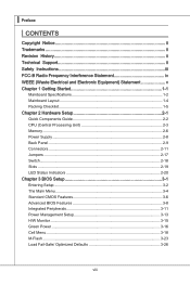
... instruction below to select "Specify Additional Device". For Windows Vista: During the Operating system installation, after the RAID volume is done. 4. The next screen should confirm that contains the RAID driver, press the "S" key to make a SATA RAID driver for RAID controller is formatted, and Windows setup starts copying files. tinue. 9. When prompted, insert the floppy disk and press Enter. You should con- Leave the disk in the : - Select the compatible RAID controller for Windows XP: \\ChipSet\AMD...
... instruction below to select "Specify Additional Device". For Windows Vista: During the Operating system installation, after the RAID volume is done. 4. The next screen should confirm that contains the RAID driver, press the "S" key to make a SATA RAID driver for RAID controller is formatted, and Windows setup starts copying files. tinue. 9. When prompted, insert the floppy disk and press Enter. You should con- Leave the disk in the : - Select the compatible RAID controller for Windows XP: \\ChipSet\AMD...

User Guide
Page 93
The AMD chipset drivers includes RAID Driver. 4. B-9 Under the Driver tab, click on AMD chipset drivers by your need. Insert the MSI DVD into the DVD-ROM drive. 2. The driver will appear. 3. The DVD will auto-run and the setup screen will be automatically installed. MS-7549 Installing the RAID Driver Under Windows (for Non-bootable RAID Array) 1.
The AMD chipset drivers includes RAID Driver. 4. B-9 Under the Driver tab, click on AMD chipset drivers by your need. Insert the MSI DVD into the DVD-ROM drive. 2. The driver will appear. 3. The DVD will auto-run and the setup screen will be automatically installed. MS-7549 Installing the RAID Driver Under Windows (for Non-bootable RAID Array) 1.
User Guide
Page 97
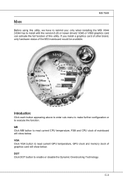
... current GPU temperature, GPU clock and memory clock of this utility, we have to remind you install a graphics card of other brand, only hardware status of the MSI mainboard would be available. MB Click MB button to enable or disable the Dynamic Overclocking Technology. MS-7549 Main Before using this utility. VGA Click VGA button to install with the version 8.26 or newer driver)/ V046 or V060 graphics card can activate the full function of graphics card will...
... current GPU temperature, GPU clock and memory clock of this utility, we have to remind you install a graphics card of other brand, only hardware status of the MSI mainboard would be available. MB Click MB button to enable or disable the Dynamic Overclocking Technology. MS-7549 Main Before using this utility. VGA Click VGA button to install with the version 8.26 or newer driver)/ V046 or V060 graphics card can activate the full function of graphics card will...


