User Guide
Page 5
... the CPU Fan 2-5 Memory ...2-7 Introduction to DDR SDRAM 2-7 DDR Module Combination 2-8 Installing DDR Modules 2-8 Power Supply ...2-9 ATX 20-Pin Power Connector: CONN1 2-9 ATX 12V Power Connector: ATX12V 2-9 Back Panel ...2-10 Mouse Connector 2-10 Keyboard Connector 2-10 Serial Port Connectors: COMA 2-11 ...USB Connectors 2-11 VGA Connector 2-11 RJ-45 LAN Jack 2-12 Audio Port Connectors 2-12 Midi/Joystick Connector...
... the CPU Fan 2-5 Memory ...2-7 Introduction to DDR SDRAM 2-7 DDR Module Combination 2-8 Installing DDR Modules 2-8 Power Supply ...2-9 ATX 20-Pin Power Connector: CONN1 2-9 ATX 12V Power Connector: ATX12V 2-9 Back Panel ...2-10 Mouse Connector 2-10 Keyboard Connector 2-10 Serial Port Connectors: COMA 2-11 ...USB Connectors 2-11 VGA Connector 2-11 RJ-45 LAN Jack 2-12 Audio Port Connectors 2-12 Midi/Joystick Connector...
User Guide
Page 8
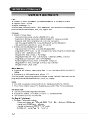
.../2X interface with 1.2GB/s bandwidth - High performance MuTIOL connect to 3.06GHz. MS-7005 Micro ATX Mainboard Mainboard Specifications CPU h Socket 478 for P4 processors (Northwood/Prescott) at 400 MHz... size without ECC. (For the uplated supporting memory modules, please visit http://www.msi.com.tw/ program/products/mainboard/mbd/pro_mbd_trp_list.php.) Slots h One AGP (Accelerated ... Integrated audio controller with 360K, 720K, 1.2M, 1.44M and 2.88 Mbytes. - 1 serial port (COMA) and 1 VGA port - 1 parallel port supports SPP/EPP/ECP mode - 6 USB 2.0/1.1 ports (Rear * 2 / Front * 4) ...
.../2X interface with 1.2GB/s bandwidth - High performance MuTIOL connect to 3.06GHz. MS-7005 Micro ATX Mainboard Mainboard Specifications CPU h Socket 478 for P4 processors (Northwood/Prescott) at 400 MHz... size without ECC. (For the uplated supporting memory modules, please visit http://www.msi.com.tw/ program/products/mainboard/mbd/pro_mbd_trp_list.php.) Slots h One AGP (Accelerated ... Integrated audio controller with 360K, 720K, 1.2M, 1.44M and 2.88 Mbytes. - 1 serial port (COMA) and 1 VGA port - 1 parallel port supports SPP/EPP/ECP mode - 6 USB 2.0/1.1 ports (Rear * 2 / Front * 4) ...
User Guide
Page 10
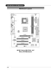
AT X Power Supply FDD1 DDR 1 DDR 2 S Y S FA N 1 IDE 2 IDE 1 MS-7005 Micro ATX Mainboard Mainboard Layout Top : mouse Bottom: keyboard CPUFAN1 Top : Parallel Port Bottom: COM A VGA Port Top : Game port Bottom: Line-Out Line-In Mic T: LAN jack B: USB ports AT X 1 2 V SiS 651 AGP Slot Realtek 8201BL PCI Slot 1 JCD1 JSP1 PCI Slot 2 Codec JAUD1 PCI Slot 3 JFP2 JUSB2 BATT + SiS 962L J BAT 1 JCI1 JFP1 JUSB1 Winbond W83697HF BIOS 651M-V Series (MS-7005) v2.X Micro ATX Mainboard 1-4
AT X Power Supply FDD1 DDR 1 DDR 2 S Y S FA N 1 IDE 2 IDE 1 MS-7005 Micro ATX Mainboard Mainboard Layout Top : mouse Bottom: keyboard CPUFAN1 Top : Parallel Port Bottom: COM A VGA Port Top : Game port Bottom: Line-Out Line-In Mic T: LAN jack B: USB ports AT X 1 2 V SiS 651 AGP Slot Realtek 8201BL PCI Slot 1 JCD1 JSP1 PCI Slot 2 Codec JAUD1 PCI Slot 3 JFP2 JUSB2 BATT + SiS 962L J BAT 1 JCI1 JFP1 JUSB1 Winbond W83697HF BIOS 651M-V Series (MS-7005) v2.X Micro ATX Mainboard 1-4

User Guide
Page 20
... No connection 3 GND Ground 4 VCC +5V 5 Keyboard Clock Keyboard clock 6 NC No connection 2-10 MS-7005 Micro ATX Mainboard Back Panel The back panel provides the following connectors: Mouse Parallel Midi/Joystick LAN Keyboard COMA VGA Port L-out L-in MIC USB Ports Mouse Connector The mainboard provides a standard PS/2® mouse mini DIN...
... No connection 3 GND Ground 4 VCC +5V 5 Keyboard Clock Keyboard clock 6 NC No connection 2-10 MS-7005 Micro ATX Mainboard Back Panel The back panel provides the following connectors: Mouse Parallel Midi/Joystick LAN Keyboard COMA VGA Port L-out L-in MIC USB Ports Mouse Connector The mainboard provides a standard PS/2® mouse mini DIN...

User Guide
Page 21
... 1 7 +Data 1 8 GND DESCRIPTION +5V Negative Data Channel 0 Positive Data Channel 0 Ground +5V Negative Data Channel 1 Positive Data Channel 1 Ground VGA Connector The mainboard provides a DB 15-pin female connector to it. Hardware Setup Serial Port Connectors: COMA The mainboard offers one 9-pin male DIN connector... as keyboard, mouse or other serial device directly to connect a VGA monitor. 5 1 15 11 VGA Connector (DB 15-pin) Pin Signal Description Pin 1 RED 2 3 BLUE 4 5 GND 6 7 GND 8 9 +5V ...
... 1 7 +Data 1 8 GND DESCRIPTION +5V Negative Data Channel 0 Positive Data Channel 0 Ground +5V Negative Data Channel 1 Positive Data Channel 1 Ground VGA Connector The mainboard provides a DB 15-pin female connector to it. Hardware Setup Serial Port Connectors: COMA The mainboard offers one 9-pin male DIN connector... as keyboard, mouse or other serial device directly to connect a VGA monitor. 5 1 15 11 VGA Connector (DB 15-pin) Pin Signal Description Pin 1 RED 2 3 BLUE 4 5 GND 6 7 GND 8 9 +5V ...

User Guide
Page 36
..., 5.25 in.], [720K, 3.5 in.], [1.44M, 3.5 in.], [2.88M, 3.5 in]. Floppy 3 Mode Support The item allows you to set the type of the system. Available options: [EGA/VGA], [CGA 40], [CGA 80], [MONO]. Available options are : [Disabled], [Drive A], [Drive B], [Both]. Base/Extended/Total Memory The three items show the memory status of video... adapter used for either a disk or a key- Video The setting controls the type of your system (read only). 3-6 MS-7005 Micro ATX Mainboard Drive A/B This item allows you to set the Floppy 3 Mode.
..., 5.25 in.], [720K, 3.5 in.], [1.44M, 3.5 in.], [2.88M, 3.5 in]. Floppy 3 Mode Support The item allows you to set the type of the system. Available options: [EGA/VGA], [CGA 40], [CGA 80], [MONO]. Available options are : [Disabled], [Drive A], [Drive B], [Both]. Base/Extended/Total Memory The three items show the memory status of video... adapter used for either a disk or a key- Video The setting controls the type of your system (read only). 3-6 MS-7005 Micro ATX Mainboard Drive A/B This item allows you to set the Floppy 3 Mode.
User Guide
Page 44
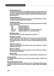
... [3] or [1]. Settings: [PCI Slot], [AGP]. Setting options: [4MB], [8MB], [16MB], [32MB], [64MB]. 3-14 Selecting [Auto] allows BIOS to the VGA card. Settings: [Disabled], [3F8/IRQ4], [2F8/IRQ3], [3E8/IRQ4], [2E8/IRQ3], [Auto]. Parallel Port Mode This item selects the operating mode for the onboard...the exact memory size shared to automatically determine the correct base I /O port address and IRQ of the onboard parallel port. MS-7005 Micro ATX Mainboard Onboard Serial Port 1 The item specify the base I/O port address and IRQ for the onboard Midi Port. Midi Port IRQ The ...
... [3] or [1]. Settings: [PCI Slot], [AGP]. Setting options: [4MB], [8MB], [16MB], [32MB], [64MB]. 3-14 Selecting [Auto] allows BIOS to the VGA card. Settings: [Disabled], [3F8/IRQ4], [2F8/IRQ3], [3E8/IRQ4], [2E8/IRQ3], [Auto]. Parallel Port Mode This item selects the operating mode for the onboard...the exact memory size shared to automatically determine the correct base I /O port address and IRQ of the onboard parallel port. MS-7005 Micro ATX Mainboard Onboard Serial Port 1 The item specify the base I/O port address and IRQ for the onboard Midi Port. Midi Port IRQ The ...

User Guide
Page 49
...if any ISA bus adapter in the PCI device configuration space is the VGA Palette Snoop bit (0 is directed to both the PCI VGA device's palette registers and the ISA VGA device's palette registers, permitting the palette registers of both VGA devices to be identical. The setting must be reserved for further request... handle data from the CPU on each IRQ a type depending on every video device. Bit 5 of the command register in the system requires VGA palette snooping. 3-19 BIOS Setup IRQ Resources list IRQ 3/4/5/7/9/10/11/12/14/15 for users to set each set of palette registers on ...
...if any ISA bus adapter in the PCI device configuration space is the VGA Palette Snoop bit (0 is directed to both the PCI VGA device's palette registers and the ISA VGA device's palette registers, permitting the palette registers of both VGA devices to be identical. The setting must be reserved for further request... handle data from the CPU on each IRQ a type depending on every video device. Bit 5 of the command register in the system requires VGA palette snooping. 3-19 BIOS Setup IRQ Resources list IRQ 3/4/5/7/9/10/11/12/14/15 for users to set each set of palette registers on ...


