User Guide
Page 5
...for Socket 478 2-4 Installing the CPU Fan 2-5 Memory ...2-7 Introduction to DDR SDRAM 2-7 DDR Module Combination 2-8 Installing DDR Modules 2-8 Power Supply ...2-9 ATX 20-Pin Power Connector: CONN1 2-9 ATX 12V Power Connector: ATX12V 2-9 Back Panel ...2-10 Mouse Connector 2-10 Keyboard Connector 2-10 Serial Port Connectors: COMA 2-11 USB Connectors 2-11 VGA ... Connector: FDD1 2-14 Fan Power Connectors: CPUFAN1/SYSFAN1 2-14 Hard Disk Connectors: IDE1 & IDE2 2-15 CD-In Connector: JCD1 2-16 v Getting Started 1-1 Mainboard Specifications 1-2 Mainboard Layout 1-4 Chapter 2.
...for Socket 478 2-4 Installing the CPU Fan 2-5 Memory ...2-7 Introduction to DDR SDRAM 2-7 DDR Module Combination 2-8 Installing DDR Modules 2-8 Power Supply ...2-9 ATX 20-Pin Power Connector: CONN1 2-9 ATX 12V Power Connector: ATX12V 2-9 Back Panel ...2-10 Mouse Connector 2-10 Keyboard Connector 2-10 Serial Port Connectors: COMA 2-11 USB Connectors 2-11 VGA ... Connector: FDD1 2-14 Fan Power Connectors: CPUFAN1/SYSFAN1 2-14 Hard Disk Connectors: IDE1 & IDE2 2-15 CD-In Connector: JCD1 2-16 v Getting Started 1-1 Mainboard Specifications 1-2 Mainboard Layout 1-4 Chapter 2.
User Guide
Page 7
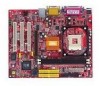
The 651M-V Series is based on SiS® 651 (702 pin BGA) & SiS® 962L MuTIOL Media I/O (371 BGA) chipsets and provides 6 USB 2.0 ports for purchasing 651M-V Series (MS-7005) v2.X Micro ATX mainboard. With all these special designs, the 651M-V Series delivers a high performance and professional desktop platform solution. 1-1 Getting Started Getting Started Thank you for high-speed data transmission.
The 651M-V Series is based on SiS® 651 (702 pin BGA) & SiS® 962L MuTIOL Media I/O (371 BGA) chipsets and provides 6 USB 2.0 ports for purchasing 651M-V Series (MS-7005) v2.X Micro ATX mainboard. With all these special designs, the 651M-V Series delivers a high performance and professional desktop platform solution. 1-1 Getting Started Getting Started Thank you for high-speed data transmission.
User Guide
Page 8
MS-7005 Micro ATX Mainboard Mainboard Specifications CPU h Socket 478 for P4 processors (Northwood/Prescott) at 400 MHz/533 MHz h Supports up to 2GB memory size without ECC. (For the uplated supporting memory modules, please visit http://www.msi.com.tw/ program/products/mainboard/mbd/pro_mbd_trp_list.php.) Slots ... DMA 33/66/100/133 operation modes. h Hyper-Threading CPU. (For the latest information about CPU, please visit http://www.msi.com.tw/program/ products/mainboard/mbd/pro_mbd_cpu_support.php) Chipset h SiS 651 (702 pin BGA) - High throughput SiS MuTIOL connect to SiS962L MuTIOL Media I ...
MS-7005 Micro ATX Mainboard Mainboard Specifications CPU h Socket 478 for P4 processors (Northwood/Prescott) at 400 MHz/533 MHz h Supports up to 2GB memory size without ECC. (For the uplated supporting memory modules, please visit http://www.msi.com.tw/ program/products/mainboard/mbd/pro_mbd_trp_list.php.) Slots ... DMA 33/66/100/133 operation modes. h Hyper-Threading CPU. (For the latest information about CPU, please visit http://www.msi.com.tw/program/ products/mainboard/mbd/pro_mbd_cpu_support.php) Chipset h SiS 651 (702 pin BGA) - High throughput SiS MuTIOL connect to SiS962L MuTIOL Media I ...
User Guide
Page 10
AT X Power Supply FDD1 DDR 1 DDR 2 S Y S FA N 1 IDE 2 IDE 1 MS-7005 Micro ATX Mainboard Mainboard Layout Top : mouse Bottom: keyboard CPUFAN1 Top : Parallel Port Bottom: COM A VGA Port Top : Game port Bottom: Line-Out Line-In Mic T: LAN jack B: USB ports AT X 1 2 V SiS 651 AGP Slot Realtek 8201BL PCI Slot 1 JCD1 JSP1 PCI Slot 2 Codec JAUD1 PCI Slot 3 JFP2 JUSB2 BATT + SiS 962L J BAT 1 JCI1 JFP1 JUSB1 Winbond W83697HF BIOS 651M-V Series (MS-7005) v2.X Micro ATX Mainboard 1-4
AT X Power Supply FDD1 DDR 1 DDR 2 S Y S FA N 1 IDE 2 IDE 1 MS-7005 Micro ATX Mainboard Mainboard Layout Top : mouse Bottom: keyboard CPUFAN1 Top : Parallel Port Bottom: COM A VGA Port Top : Game port Bottom: Line-Out Line-In Mic T: LAN jack B: USB ports AT X 1 2 V SiS 651 AGP Slot Realtek 8201BL PCI Slot 1 JCD1 JSP1 PCI Slot 2 Codec JAUD1 PCI Slot 3 JFP2 JUSB2 BATT + SiS 962L J BAT 1 JCI1 JFP1 JUSB1 Winbond W83697HF BIOS 651M-V Series (MS-7005) v2.X Micro ATX Mainboard 1-4

User Guide
Page 11
It also provides the instructions on the mainboard. While doing the installation, be careful in holding the comonents and follow the installation procedures. 2-1 Hardware Setup Chapter 2. Hardware Setup Hardware Setup This chapter tells you how to install the CPU, memory modules, and expansion cards, as well as how to setup the jumpers on connecting the peripheral devices, such as the mouse, keyboard, etc.
It also provides the instructions on the mainboard. While doing the installation, be careful in holding the comonents and follow the installation procedures. 2-1 Hardware Setup Chapter 2. Hardware Setup Hardware Setup This chapter tells you how to install the CPU, memory modules, and expansion cards, as well as how to setup the jumpers on connecting the peripheral devices, such as the mouse, keyboard, etc.

User Guide
Page 13
...MHz 533 MHz DDR 266 OK OK DDR 333 OK OK MSI Reminds You... For the latest information about CPU, please visit http://www.msi.com.tw/ program/products/mainboard/mbd/pro_mbd_cpu_support.php Example of CPU. 2-3 The mainboard uses a CPU socket called PGA478 for easy CPU installation.... Replacing the CPU While replacing the CPU, always turn off the ATX power supply or unplug the power ...
...MHz 533 MHz DDR 266 OK OK DDR 333 OK OK MSI Reminds You... For the latest information about CPU, please visit http://www.msi.com.tw/ program/products/mainboard/mbd/pro_mbd_cpu_support.php Example of CPU. 2-3 The mainboard uses a CPU socket called PGA478 for easy CPU installation.... Replacing the CPU While replacing the CPU, always turn off the ATX power supply or unplug the power ...

User Guide
Page 14
...CPU down the CPU Close Lever 2-4 As the CPU is likely to move while the lever is being closed, always close the lever with your mainboard. Gold arrow Correct CPU placement O 5. Sliding Plate 90 degree 3. If the CPU is properly and completely embedded into the socket and close the...away from the socket. The CPU can not be completely embedded into the socket and can only fit in the correct orientation. MS-7005 Micro ATX Mainboard CPU Installation Procedures for the gold arrow. The gold arrow should be seen. Make sure to raise the lever up to your fingers ...
...CPU down the CPU Close Lever 2-4 As the CPU is likely to move while the lever is being closed, always close the lever with your mainboard. Gold arrow Correct CPU placement O 5. Sliding Plate 90 degree 3. If the CPU is properly and completely embedded into the socket and close the...away from the socket. The CPU can not be completely embedded into the socket and can only fit in the correct orientation. MS-7005 Micro ATX Mainboard CPU Installation Procedures for the gold arrow. The gold arrow should be seen. Make sure to raise the lever up to your fingers ...

User Guide
Page 16
fan power cable NOTES 2-6 MS-7005 Micro ATX Mainboard 5. Connect the fan power cable from the mounted fan to the 3-pin fan power connector on the board.
fan power cable NOTES 2-6 MS-7005 Micro ATX Mainboard 5. Connect the fan power cable from the mounted fan to the 3-pin fan power connector on the board.

User Guide
Page 17
Hardware Setup Memory The mainboard provides two 184-pin unbuffered DDR200/DDR266/DDR333 DDR SDRAM, and supports the memory size up to 3. 3 volts used in SDR SDRAM, and requires 184-...-pin DIMM modules used by transferring data twice per cycle. To operate properly, at least one DIMM module must be installed. com.tw/program/products/mainboard/mbd/pro_mbd_trp_list.php. DDR DIMM Slots (DDR 1~2) Introduction to DDR SDRAM DDR (Double Data Rate) SDRAM is similar to conventional SDRAM, but doubles the rate...
Hardware Setup Memory The mainboard provides two 184-pin unbuffered DDR200/DDR266/DDR333 DDR SDRAM, and supports the memory size up to 3. 3 volts used in SDR SDRAM, and requires 184-...-pin DIMM modules used by transferring data twice per cycle. To operate properly, at least one DIMM module must be installed. com.tw/program/products/mainboard/mbd/pro_mbd_trp_list.php. DDR DIMM Slots (DDR 1~2) Introduction to DDR SDRAM DDR (Double Data Rate) SDRAM is similar to conventional SDRAM, but doubles the rate...
User Guide
Page 18
You can be installed on the memory module is properly inserted in the socket. 3. Volt Notch MSI Reminds You... Then push it in until the golden finger on the slots in any combination as follows: Slot DDR 1 (Bank 0 & 1) DDR 2 (Bank 2 & 3) Memory Module S/D ...the module is deeply inserted in the socket. 2-8 Memory modules can install either single- or double-sided modules to meet your own needs. MS-7005 Micro ATX Mainboard DDR Module Combination Install at each side of module. The module will automatically close. The DDR DIMM has only one DIMM module on the center...
You can be installed on the memory module is properly inserted in the socket. 3. Volt Notch MSI Reminds You... Then push it in until the golden finger on the slots in any combination as follows: Slot DDR 1 (Bank 0 & 1) DDR 2 (Bank 2 & 3) Memory Module S/D ...the module is deeply inserted in the socket. 2-8 Memory modules can install either single- or double-sided modules to meet your own needs. MS-7005 Micro ATX Mainboard DDR Module Combination Install at each side of module. The module will automatically close. The DDR DIMM has only one DIMM module on the center...

User Guide
Page 19
... supply connector, always make sure the plug of the power supply is used to provide power to ensure that all components are aligned. ATX 12V Power Connector: ATX12V This 12V power connector is inserted in the proper orientation and the pins are installed properly to the CPU. ... GND 18 -5V 19 5V 20 5V 3 4 1 2 ATX12V ATX12V Pin Definition PIN SIGNAL 1 GND 2 GND 3 12V 4 12V 2-9 To connect to an ATX power supply. Hardware Setup Power Supply The mainboard supports ATX power supply for the power system. Then push down the power supply firmly into the connector...
... supply connector, always make sure the plug of the power supply is used to provide power to ensure that all components are aligned. ATX 12V Power Connector: ATX12V This 12V power connector is inserted in the proper orientation and the pins are installed properly to the CPU. ... GND 18 -5V 19 5V 20 5V 3 4 1 2 ATX12V ATX12V Pin Definition PIN SIGNAL 1 GND 2 GND 3 12V 4 12V 2-9 To connect to an ATX power supply. Hardware Setup Power Supply The mainboard supports ATX power supply for the power system. Then push down the power supply firmly into the connector...

User Guide
Page 20
... 2 NC 3 GND 4 VCC 5 Mouse Clock 6 NC DESCRIPTION Mouse DATA No connection Ground +5V Mouse clock No connection Keyboard Connector The mainboard provides a standard PS/2® keyboard mini DIN connector for attaching a PS/2® mouse. You can plug a PS/2® mouse directly into... DATA 2 NC No connection 3 GND Ground 4 VCC +5V 5 Keyboard Clock Keyboard clock 6 NC No connection 2-10 MS-7005 Micro ATX Mainboard Back Panel The back panel provides the following connectors: Mouse Parallel Midi/Joystick LAN Keyboard COMA VGA Port L-out L-in MIC USB Ports...
... 2 NC 3 GND 4 VCC 5 Mouse Clock 6 NC DESCRIPTION Mouse DATA No connection Ground +5V Mouse clock No connection Keyboard Connector The mainboard provides a standard PS/2® keyboard mini DIN connector for attaching a PS/2® mouse. You can plug a PS/2® mouse directly into... DATA 2 NC No connection 3 GND Ground 4 VCC +5V 5 Keyboard Clock Keyboard clock 6 NC No connection 2-10 MS-7005 Micro ATX Mainboard Back Panel The back panel provides the following connectors: Mouse Parallel Midi/Joystick LAN Keyboard COMA VGA Port L-out L-in MIC USB Ports...

User Guide
Page 21
... GND 5 VCC 6 -Data 1 7 +Data 1 8 GND DESCRIPTION +5V Negative Data Channel 0 Positive Data Channel 0 Ground +5V Negative Data Channel 1 Positive Data Channel 1 Ground VGA Connector The mainboard provides a DB 15-pin female connector to it. Pin Definition 1 2 3 4 5 PIN 1 2 3 4 6 7 8 9 5 9-Pin Male DIN Connector 6 7 8 9 SIGNAL DCD... Ready) Ground Data Set Ready Request To Send Clear To Send Ring Indicate USB Connectors The mainboard provides a UHCI (Universal Host Controller Interface) Universal Serial Bus root for attaching USB devices such as serial port COM A.
... GND 5 VCC 6 -Data 1 7 +Data 1 8 GND DESCRIPTION +5V Negative Data Channel 0 Positive Data Channel 0 Ground +5V Negative Data Channel 1 Positive Data Channel 1 Ground VGA Connector The mainboard provides a DB 15-pin female connector to it. Pin Definition 1 2 3 4 5 PIN 1 2 3 4 6 7 8 9 5 9-Pin Male DIN Connector 6 7 8 9 SIGNAL DCD... Ready) Ground Data Set Ready Request To Send Clear To Send Ring Indicate USB Connectors The mainboard provides a UHCI (Universal Host Controller Interface) Universal Serial Bus root for attaching USB devices such as serial port COM A.
User Guide
Page 22
You can turn rear audio connectors from 2-channel to 4-/6-channel audio. 2-12 Mic is a connector for Speakers or Headphones. MS-7005 Micro ATX Mainboard RJ-45 LAN Jack The mainboard provides one standard RJ-45 jack for connection to the LAN jack. RJ-45 LAN Jack Pin Definition PIN SIGNAL 1 TDP 2 TDN...Pair Not Used Not Used Audio Port Connectors Line Out is a connector for microphones. 1/8" Stereo Audio Connectors Line Out Line In MIC MSI Reminds You... Line In is provided to offer support for external CD player, Tape player, or other audio devices. For advanced audio ...
You can turn rear audio connectors from 2-channel to 4-/6-channel audio. 2-12 Mic is a connector for Speakers or Headphones. MS-7005 Micro ATX Mainboard RJ-45 LAN Jack The mainboard provides one standard RJ-45 jack for connection to the LAN jack. RJ-45 LAN Jack Pin Definition PIN SIGNAL 1 TDP 2 TDN...Pair Not Used Not Used Audio Port Connectors Line Out is a connector for microphones. 1/8" Stereo Audio Connectors Line Out Line In MIC MSI Reminds You... Line In is provided to offer support for external CD player, Tape player, or other audio devices. For advanced audio ...

User Guide
Page 23
... Ground 25 GND Ground 2-13 Hardware Setup Midi/Joystick Connector You can connect a joystick or game pad to this connector. Parallel Port Connector: LPT1 The mainboard provides a 25-pin female centronic connector as LPT.
... Ground 25 GND Ground 2-13 Hardware Setup Midi/Joystick Connector You can connect a joystick or game pad to this connector. Parallel Port Connector: LPT1 The mainboard provides a 25-pin female centronic connector as LPT.
User Guide
Page 24
... the fan control. GND +12V SENSOR CPUFAN1 GND +12V SENSOR SYSFAN1 MSI Reminds You... 1. Always consult the vendors for proper CPU cooling fan. 2. MS-7005 Micro ATX Mainboard Connectors The mainboard provides connectors to connect to the actual CPU temperature. 2-14 Floppy Disk... Drive Connector: FDD1 The mainboard provides a standard floppy disk drive connector that will automatically control ...
... the fan control. GND +12V SENSOR CPUFAN1 GND +12V SENSOR SYSFAN1 MSI Reminds You... 1. Always consult the vendors for proper CPU cooling fan. 2. MS-7005 Micro ATX Mainboard Connectors The mainboard provides connectors to connect to the actual CPU temperature. 2-14 Floppy Disk... Drive Connector: FDD1 The mainboard provides a standard floppy disk drive connector that will automatically control ...

User Guide
Page 25
MSI Reminds You... You can connect up to IDE1. IDE2 IDE1 IDE1 (Primary IDE Connector) The first hard drive should always be connected to four hard disk drives, CD-ROM, 120MB Floppy and other devices. Refer to Slave mode by setting its jumper. Hardware Setup Hard Disk Connectors: IDE1 & IDE2 The mainboard has...
MSI Reminds You... You can connect up to IDE1. IDE2 IDE1 IDE1 (Primary IDE Connector) The first hard drive should always be connected to four hard disk drives, CD-ROM, 120MB Floppy and other devices. Refer to Slave mode by setting its jumper. Hardware Setup Hard Disk Connectors: IDE1 & IDE2 The mainboard has...
User Guide
Page 26
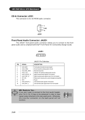
... Left channel audio signal to front panel 6 AUD_RET_R Right channel audio signal return from front panel 7 HP_ON Reserved for CD-ROM audio connector. MS-7005 Micro ATX Mainboard CD-In Connector: JCD1 The connector is compliant with Intel® Front Panel I/O Connectivity Design Guide. Otherwise, the Line-Out connector on the back panel... Filtered +5V used by analog audio circuits 5 AUD_FPOUT_R Right channel audio signal to front panel 10 AUD_RET_L Left channel audio signal return from front panel MSI Reminds You...
... Left channel audio signal to front panel 6 AUD_RET_R Right channel audio signal return from front panel 7 HP_ON Reserved for CD-ROM audio connector. MS-7005 Micro ATX Mainboard CD-In Connector: JCD1 The connector is compliant with Intel® Front Panel I/O Connectivity Design Guide. Otherwise, the Line-Out connector on the back panel... Filtered +5V used by analog audio circuits 5 AUD_FPOUT_R Right channel audio signal to front panel 10 AUD_RET_L Left channel audio signal return from front panel MSI Reminds You...

User Guide
Page 27
JCI1 Front Panel Connectors: JFP1 & JFP2 The mainboard provides two front panel connectors for electrical connection to GND Reserved. JFP1 is connected to 2-pin connector chassis switch. Do not use. If the Chassis ...
JCI1 Front Panel Connectors: JFP1 & JFP2 The mainboard provides two front panel connectors for electrical connection to GND Reserved. JFP1 is connected to 2-pin connector chassis switch. Do not use. If the Chassis ...
User Guide
Page 28
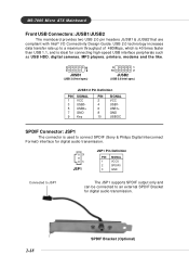
MS-7005 Micro ATX Mainboard Front USB Connectors: JUSB1/JUSB2 The mainboard provides two USB 2.0 pin headers JUSB1 & JUSB2 that are compliant with Intel® I/O Connectivity Design Guide. USB 2.0 technology increases data transfer rate up to a maximum ...
MS-7005 Micro ATX Mainboard Front USB Connectors: JUSB1/JUSB2 The mainboard provides two USB 2.0 pin headers JUSB1 & JUSB2 that are compliant with Intel® I/O Connectivity Design Guide. USB 2.0 technology increases data transfer rate up to a maximum ...


