
User Guide
Page 4
... on card or module. 9. Place the power cord such a way that could damage or cause electrical shock. 11. h Visit the MSI homepage & FAQ site for air convection hence protects the equip- Technical Support If a problem arises with the same or equivalent type recommended by a service personnel: h The power cord or plug is incorrectly replaced. h The equipment has not work according to User's Manual.
... on card or module. 9. Place the power cord such a way that could damage or cause electrical shock. 11. h Visit the MSI homepage & FAQ site for air convection hence protects the equip- Technical Support If a problem arises with the same or equivalent type recommended by a service personnel: h The power cord or plug is incorrectly replaced. h The equipment has not work according to User's Manual.
User Guide
Page 5
...the CPU Fan 2-5 Memory ...2-7 Introduction to DDR SDRAM 2-7 DDR Module Combination 2-8 Installing DDR Modules 2-8 Power Supply ...2-9 ATX 20-Pin Power Connector: CONN1 2-9 ATX 12V Power Connector: ATX12V 2-9 Back Panel ...2-10 Mouse Connector 2-10 Keyboard Connector 2-10 Serial Port Connectors: COMA 2-11 USB Connectors 2-11 VGA Connector 2-11 RJ-45 LAN Jack 2-12 Audio Port Connectors 2-12 Midi/Joystick Connector 2-13 Parallel Port Connector: LPT1 2-13 Connectors ...2-14 Floppy Disk Drive Connector: FDD1 2-14 Fan Power Connectors: CPUFAN1/SYSFAN1 2-14 Hard Disk Connectors: IDE1...
...the CPU Fan 2-5 Memory ...2-7 Introduction to DDR SDRAM 2-7 DDR Module Combination 2-8 Installing DDR Modules 2-8 Power Supply ...2-9 ATX 20-Pin Power Connector: CONN1 2-9 ATX 12V Power Connector: ATX12V 2-9 Back Panel ...2-10 Mouse Connector 2-10 Keyboard Connector 2-10 Serial Port Connectors: COMA 2-11 USB Connectors 2-11 VGA Connector 2-11 RJ-45 LAN Jack 2-12 Audio Port Connectors 2-12 Midi/Joystick Connector 2-13 Parallel Port Connector: LPT1 2-13 Connectors ...2-14 Floppy Disk Drive Connector: FDD1 2-14 Fan Power Connectors: CPUFAN1/SYSFAN1 2-14 Hard Disk Connectors: IDE1...

User Guide
Page 6
... 2-18 SPDIF Connector: JSP1 2-18 Jumpers ...2-19 Clear CMOS Jumper: JBAT1 2-19 Slots ...2-20 AGP (Accelerated Graphics Port) Slot 2-20 PCI (Peripheral Component Interconnect) Slots 2-20 PCI Interrupt Request Routing 2-20 Chapter 3. BIOS Setup 3-1 Entering Setup ...3-2 The Main Menu 3-3 Standard CMOS Features 3-5 Advanced BIOS Features 3-7 Advanced Chipset Features 3-10 Integrated Peripherals 3-12 Power Management Setup 3-15 PNP/PCI Configurations 3-18 PC Health Status 3-20 Frequency/Voltage Control 3-21 Load Fail-Safe/Optimized Defaults 3-22 Set Supervisor/User Password 3-23...
... 2-18 SPDIF Connector: JSP1 2-18 Jumpers ...2-19 Clear CMOS Jumper: JBAT1 2-19 Slots ...2-20 AGP (Accelerated Graphics Port) Slot 2-20 PCI (Peripheral Component Interconnect) Slots 2-20 PCI Interrupt Request Routing 2-20 Chapter 3. BIOS Setup 3-1 Entering Setup ...3-2 The Main Menu 3-3 Standard CMOS Features 3-5 Advanced BIOS Features 3-7 Advanced Chipset Features 3-10 Integrated Peripherals 3-12 Power Management Setup 3-15 PNP/PCI Configurations 3-18 PC Health Status 3-20 Frequency/Voltage Control 3-21 Load Fail-Safe/Optimized Defaults 3-22 Set Supervisor/User Password 3-23...
User Guide
Page 8
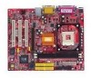
.../ECP mode - 6 USB 2.0/1.1 ports (Rear * 2 / Front * 4) 1-2 Advanced power management and PC2001 compliance - Integrated PCI to LPCC bridge Main Memory h Supports two memory banks using two 184-pin unbuffered DDR 200/266/333 DIMMs. h Supports up to 3.06GHz. On-Board Peripherals h On-Board Peripherals include: - 1 floppy port supports 2 FDDs with fast write transaction - MS-7005 Micro ATX Mainboard Mainboard Specifications CPU h Socket 478 for P4 processors (Northwood/Prescott) at 400 MHz/533 MHz h Supports up to 2GB memory size...
.../ECP mode - 6 USB 2.0/1.1 ports (Rear * 2 / Front * 4) 1-2 Advanced power management and PC2001 compliance - Integrated PCI to LPCC bridge Main Memory h Supports two memory banks using two 184-pin unbuffered DDR 200/266/333 DIMMs. h Supports up to 3.06GHz. On-Board Peripherals h On-Board Peripherals include: - 1 floppy port supports 2 FDDs with fast write transaction - MS-7005 Micro ATX Mainboard Mainboard Specifications CPU h Socket 478 for P4 processors (Northwood/Prescott) at 400 MHz/533 MHz h Supports up to 2GB memory size...
User Guide
Page 9
... port - 1 RJ-45 LAN connector Audio h AC97 link controller integrated in SiS 962L SB. Compliance with AC97 2.2 Spec - Dimension h Micro-ATX Form Factor: 24.5 cm (L) x 20.0 cm (W). Meets PC2001 audio performance requirement LAN h SiS 962L integrated MAC + Realtek 8201BL PHY - Compliance with PCI 2.2 and PC99 standard. h Supports Wake-On-LAN and remote wake-up. BIOS h 4MB Award BIOS with PNP BIOS, ACPI, SMBIOS 2.3, Green and Boot Block. h Provides DMI 2.0, WFM 2.0, WOL, WOR, chassis...
... port - 1 RJ-45 LAN connector Audio h AC97 link controller integrated in SiS 962L SB. Compliance with AC97 2.2 Spec - Dimension h Micro-ATX Form Factor: 24.5 cm (L) x 20.0 cm (W). Meets PC2001 audio performance requirement LAN h SiS 962L integrated MAC + Realtek 8201BL PHY - Compliance with PCI 2.2 and PC99 standard. h Supports Wake-On-LAN and remote wake-up. BIOS h 4MB Award BIOS with PNP BIOS, ACPI, SMBIOS 2.3, Green and Boot Block. h Provides DMI 2.0, WFM 2.0, WOL, WOR, chassis...

User Guide
Page 20
... LAN Keyboard COMA VGA Port L-out L-in MIC USB Ports Mouse Connector The mainboard provides a standard PS/2® mouse mini DIN connector for attaching a PS/2® keyboard. The connector location and pin assignments are as follows: 6 5 4 3 2 1 PS/2 Mouse (6-pin Female) Pin Definition PIN SIGNAL 1 Mouse DATA 2 NC 3 GND 4 VCC 5 Mouse Clock 6 NC DESCRIPTION Mouse DATA No connection Ground +5V Mouse clock No connection Keyboard Connector The mainboard provides a standard PS/2® keyboard mini DIN connector...
... LAN Keyboard COMA VGA Port L-out L-in MIC USB Ports Mouse Connector The mainboard provides a standard PS/2® mouse mini DIN connector for attaching a PS/2® keyboard. The connector location and pin assignments are as follows: 6 5 4 3 2 1 PS/2 Mouse (6-pin Female) Pin Definition PIN SIGNAL 1 Mouse DATA 2 NC 3 GND 4 VCC 5 Mouse Clock 6 NC DESCRIPTION Mouse DATA No connection Ground +5V Mouse clock No connection Keyboard Connector The mainboard provides a standard PS/2® keyboard mini DIN connector...

User Guide
Page 21
... Set Ready Request To Send Clear To Send Ring Indicate USB Connectors The mainboard provides a UHCI (Universal Host Controller Interface) Universal Serial Bus root for attaching USB devices such as serial port COM A. This port is 16550A high speed communication ports that send/receive 16 bytes FIFOs. Hardware Setup Serial Port Connectors: COMA The mainboard offers one 9-pin male DIN connector as keyboard, mouse or other serial device directly to connect a VGA monitor. 5 1 15 11 VGA Connector (DB 15-pin) Pin Signal Description Pin...
... Set Ready Request To Send Clear To Send Ring Indicate USB Connectors The mainboard provides a UHCI (Universal Host Controller Interface) Universal Serial Bus root for attaching USB devices such as serial port COM A. This port is 16550A high speed communication ports that send/receive 16 bytes FIFOs. Hardware Setup Serial Port Connectors: COMA The mainboard offers one 9-pin male DIN connector as keyboard, mouse or other serial device directly to connect a VGA monitor. 5 1 15 11 VGA Connector (DB 15-pin) Pin Signal Description Pin...
User Guide
Page 24
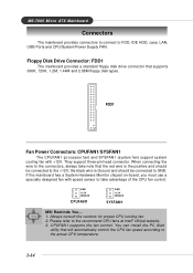
... CPU fan control. You can install the PC Alert utility that supports 360K, 720K, 1.2M, 1.44M and 2.88M floppy disk types. Always consult the vendors for proper CPU cooling fan. 2. If the mainboard has a System Hardware Monitor chipset on-board, you must use a specially designed fan with +12V. Floppy Disk Drive Connector: FDD1 The mainboard provides a standard floppy disk drive connector that will automatically control the CPU fan speed according to GND. FDD1 Fan Power Connectors: CPUFAN1/SYSFAN1 The CPUFAN1 (processor fan) and SYSFAN1 (system fan) support...
... CPU fan control. You can install the PC Alert utility that supports 360K, 720K, 1.2M, 1.44M and 2.88M floppy disk types. Always consult the vendors for proper CPU cooling fan. 2. If the mainboard has a System Hardware Monitor chipset on-board, you must use a specially designed fan with +12V. Floppy Disk Drive Connector: FDD1 The mainboard provides a standard floppy disk drive connector that will automatically control the CPU fan speed according to GND. FDD1 Fan Power Connectors: CPUFAN1/SYSFAN1 The CPUFAN1 (processor fan) and SYSFAN1 (system fan) support...
User Guide
Page 26
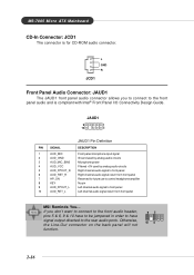
MS-7005 Micro ATX Mainboard CD-In Connector: JCD1 The connector is compliant with Intel® Front Panel I/O Connectivity Design Guide. JAUD1 9 1 10 2 JAUD1 Pin Definition PIN SIGNAL DESCRIPTION 1 AUD_MIC Front panel microphone input signal 2 AUD_GND Ground used by analog audio circuits 3 AUD_MIC_BIAS Microphone power 4 AUD_VCC Filtered +5V used by analog audio circuits 5 AUD_FPOUT_R Right channel audio signal to front panel 6 AUD_RET_R Right channel audio signal return from front panel MSI Reminds You... If...
MS-7005 Micro ATX Mainboard CD-In Connector: JCD1 The connector is compliant with Intel® Front Panel I/O Connectivity Design Guide. JAUD1 9 1 10 2 JAUD1 Pin Definition PIN SIGNAL DESCRIPTION 1 AUD_MIC Front panel microphone input signal 2 AUD_GND Ground used by analog audio circuits 3 AUD_MIC_BIAS Microphone power 4 AUD_VCC Filtered +5V used by analog audio circuits 5 AUD_FPOUT_R Right channel audio signal to front panel 6 AUD_RET_R Right channel audio signal return from front panel MSI Reminds You... If...

User Guide
Page 27
... Hard disk active LED MSG LED pull-up Reset Switch low reference pull-down to GND Power Switch high reference pull-up Reset Switch high reference pull-up Power Switch low reference pull-down to the front panel switches and LEDs. The system will be short. Do not use. JFP2 Pin Definition PIN SIGNAL PIN SIGNAL 1 GND 2 SPK- 3 SLED 4 BUZ+ 5 PLED 6 BUZ- 7 NC 8 SPK+ 2-17 To clear the warning, you must enter the BIOS setting and clear...
... Hard disk active LED MSG LED pull-up Reset Switch low reference pull-down to GND Power Switch high reference pull-up Reset Switch high reference pull-up Power Switch low reference pull-down to the front panel switches and LEDs. The system will be short. Do not use. JFP2 Pin Definition PIN SIGNAL PIN SIGNAL 1 GND 2 SPK- 3 SLED 4 BUZ+ 5 PLED 6 BUZ- 7 NC 8 SPK+ 2-17 To clear the warning, you must enter the BIOS setting and clear...

User Guide
Page 29
With the CMOS RAM, the system can clear CMOS by shorting 2-3 pin while the system is a CMOS RAM on board that has a power supply from external battery to set the computer's function. it is on . Hardware Setup Jumpers The motherboard provides the following jumpers for you want to clear the system configuration, use of system configuration. Avoid clearing the CMOS while the system is turned on ; You can automatically boot OS every time it will explain...
With the CMOS RAM, the system can clear CMOS by shorting 2-3 pin while the system is a CMOS RAM on board that has a power supply from external battery to set the computer's function. it is on . Hardware Setup Jumpers The motherboard provides the following jumpers for you want to clear the system configuration, use of system configuration. Avoid clearing the CMOS while the system is turned on ; You can automatically boot OS every time it will explain...
User Guide
Page 30
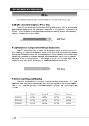
... PCI slot (PCI5) also works as jumpers, switches or BIOS configuration. The PCI IRQ pins are hardware lines over which allows you to make sure that you to insert the expansion cards to directly access main memory. The slot supports 4x/2x AGP card. It introduces a 66MHz, 32-bit channel for the expansion card, such as a communcation slot, which devices can send interrupt signals to the microprocessor. When adding or removing expansion cards...
... PCI slot (PCI5) also works as jumpers, switches or BIOS configuration. The PCI IRQ pins are hardware lines over which allows you to make sure that you to insert the expansion cards to directly access main memory. The slot supports 4x/2x AGP card. It introduces a 66MHz, 32-bit channel for the expansion card, such as a communcation slot, which devices can send interrupt signals to the microprocessor. When adding or removing expansion cards...

User Guide
Page 35
... your hard disk drive type is not matched or listed, you select [Manual], related information is asked to be entered to the following items. Enter the information directly from 1 to select [Manual], [None] or [Auto] type. IDE Primary/Secondary Master/Slave Press PgUp/ or PgDn/ to 31 can be keyed by users. BIOS Setup Standard CMOS Features The items in Standard CMOS Features Menu are [CHS], [LBA], [Large], [Auto]. The hard disk...
... your hard disk drive type is not matched or listed, you select [Manual], related information is asked to be entered to the following items. Enter the information directly from 1 to select [Manual], [None] or [Auto] type. IDE Primary/Secondary Master/Slave Press PgUp/ or PgDn/ to 31 can be keyed by users. BIOS Setup Standard CMOS Features The items in Standard CMOS Features Menu are [CHS], [LBA], [Large], [Auto]. The hard disk...
User Guide
Page 38
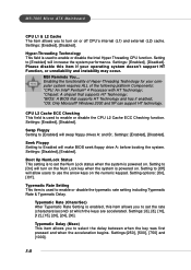
... instability may occur. Settings: [Enabled], [Disabled]. Settings: [6], [8], [10], [12], [15], [20], [24], [30]. Swap Floppy Setting to [Enabled] will increase the system performance. Setting to [On] will turn on . Seek Floppy Setting to Enabled will allow users to use the arrow keys on . Settings: [Disabled], [Enabled]. Setting to [Off] will make BIOS seek floppy drive A: before booting the system. Typematic Rate Setting This item is powered on the numeric keypad. MSI Reminds You... Settings: [Enabled], [Disabled]. Settings:[250], [500], [750...
... instability may occur. Settings: [Enabled], [Disabled]. Settings: [6], [8], [10], [12], [15], [20], [24], [30]. Swap Floppy Setting to [Enabled] will increase the system performance. Setting to [On] will turn on . Seek Floppy Setting to Enabled will allow users to use the arrow keys on . Settings: [Disabled], [Enabled]. Setting to [Off] will make BIOS seek floppy drive A: before booting the system. Typematic Rate Setting This item is powered on the numeric keypad. MSI Reminds You... Settings: [Enabled], [Disabled]. Settings:[250], [500], [750...
User Guide
Page 39
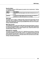
... in APIC mode. Settings: [Enabled], [Disabled]. Settings: [Enabled] and [Disabled]. 3-9 Enabling APIC mode will expand available IRQs resources for the operating system. You need to use, consult the vendor of BIOS password protection that is a utility that is able to predict hard disk failure. To find out which MPS (Multi-Processor Specification) version to be used to a safe place before the hard disk becomes offline. HDD S.M.A.R.T. Due to compliance to PC2001 design guide, the system...
... in APIC mode. Settings: [Enabled], [Disabled]. Settings: [Enabled] and [Disabled]. 3-9 Enabling APIC mode will expand available IRQs resources for the operating system. You need to use, consult the vendor of BIOS password protection that is a utility that is able to predict hard disk failure. To find out which MPS (Multi-Processor Specification) version to be used to a safe place before the hard disk becomes offline. HDD S.M.A.R.T. Due to compliance to PC2001 design guide, the system...

User Guide
Page 40
... programmed into this register are familiar with the chipset. Advanced DRAM Control 1 Press and the following sub-menu appears: System Performance This setting particularly provided by BIOS based on the configurations on the SPD (Serial Presence Detect) EEPROM on the system design. Change these settings only if you are dependent on the DRAM module. Setting options: [Safe Mode], [Normal Mode], [Fast Mode], [Turbo Mode], [Ultra Mode]. Setting options: [Auto], [2T], [1T]. 3-10
... programmed into this register are familiar with the chipset. Advanced DRAM Control 1 Press and the following sub-menu appears: System Performance This setting particularly provided by BIOS based on the configurations on the SPD (Serial Presence Detect) EEPROM on the system design. Change these settings only if you are dependent on the DRAM module. Setting options: [Safe Mode], [Normal Mode], [Fast Mode], [Turbo Mode], [Ultra Mode]. Setting options: [Auto], [2T], [1T]. 3-10
User Guide
Page 42
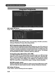
... system automatically determines the best mode for each device. Settings: [Disabled], [Enabled]. SiS OnChip PCI Device Press and the following sub-menu appears: Internal PCI/IDE The field specifies the internal primary and secondary PCI/IDE controllers. If your hard drive and your IDE hard drive supports it and the operating environment includes a DMA driver (Windows ME, XP or a third-party IDE bus master driver). Settings: [Auto], [Disabled]. IDE DMA transfer access Setting to enable BIOS support. Primary/Secondary Master/Slave Ultra DMA Ultra DMA...
... system automatically determines the best mode for each device. Settings: [Disabled], [Enabled]. SiS OnChip PCI Device Press and the following sub-menu appears: Internal PCI/IDE The field specifies the internal primary and secondary PCI/IDE controllers. If your hard drive and your IDE hard drive supports it and the operating environment includes a DMA driver (Windows ME, XP or a third-party IDE bus master driver). Settings: [Auto], [Disabled]. IDE DMA transfer access Setting to enable BIOS support. Primary/Secondary Master/Slave Ultra DMA Ultra DMA...
User Guide
Page 43
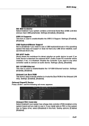
... item is disabled. Onboard Lan Boot ROM This item is used to decide whether to invoke the Boot ROM of the Onboard LAN Chip. USB Keyboard/Mouse Support Set to [Enabled] if you install add-on the system board and you wish to use a USB keyboard/mouse in this field. Setting options: [Enabled [Disabled]. 3-13 USB 2.0 Supports This item is used to enable/disable the USB 2.0 Support. If you need to use it is used . Settings: [Enabled], [Disabled]. BIOS Setup SiS USB Controller Select Enabled if your system has a floppy disk controller (FDD) installed on FDC...
... item is disabled. Onboard Lan Boot ROM This item is used to decide whether to invoke the Boot ROM of the Onboard LAN Chip. USB Keyboard/Mouse Support Set to [Enabled] if you install add-on the system board and you wish to use a USB keyboard/mouse in this field. Setting options: [Enabled [Disabled]. 3-13 USB 2.0 Supports This item is used to enable/disable the USB 2.0 Support. If you need to use it is used . Settings: [Enabled], [Disabled]. BIOS Setup SiS USB Controller Select Enabled if your system has a floppy disk controller (FDD) installed on FDC...

User Guide
Page 50
... disables the feature of your CPU, fan, overall system status, etc. Settings: [Enabled], [Reset], [Disabled]. Shutdown Temperature If the CPU temperature reaches the upper limit preset in this function, such as CPU voltages, temperatures and all of the field will be shut down automatically. To clear the warning message, set the field to prevent the CPU overheating problem. This item is available only when your mainboard has JCI1 jumper. Monitor...
... disables the feature of your CPU, fan, overall system status, etc. Settings: [Enabled], [Reset], [Disabled]. Shutdown Temperature If the CPU temperature reaches the upper limit preset in this function, such as CPU voltages, temperatures and all of the field will be shut down automatically. To clear the warning message, set the field to prevent the CPU overheating problem. This item is available only when your mainboard has JCI1 jumper. Monitor...

User Guide
Page 51
..., set to [Enabled], the system will remove (turn off) clocks from empty PCI slots to auto detect the PCI slots. CPU Frequency Use this item to [Manual]. Settings: [Manual], [Default] CPU Clock Ratio End users can introduce a temporary boost in this field. Settings: [Enabled], [Disabled]. But if you do not have any EMI problem, leave the setting at [Disabled] for frequency/voltage control. DRAM Frequency Use this item to select the appropriate frequency for EMI reduction. If you are reduced to flatter curves. Options...
..., set to [Enabled], the system will remove (turn off) clocks from empty PCI slots to auto detect the PCI slots. CPU Frequency Use this item to [Manual]. Settings: [Manual], [Default] CPU Clock Ratio End users can introduce a temporary boost in this field. Settings: [Enabled], [Disabled]. But if you do not have any EMI problem, leave the setting at [Disabled] for frequency/voltage control. DRAM Frequency Use this item to select the appropriate frequency for EMI reduction. If you are reduced to flatter curves. Options...

