
Installation Manual
Page 1
HDS Gen2 Touch Installation Manual ENGLISH lowrance.com
HDS Gen2 Touch Installation Manual ENGLISH lowrance.com

Installation Manual
Page 8
... without inbuilt sonar and structure scan. All displays are charting ready, with built-in to the dash. Power should be mounted on 10.8 V - 17 V. 6 | HDS Gen2 Touch overview | HDS Gen2 Touch Installation Manual The displays may be supplied at around 12V, but due to the variable nature of numerous optional devices that can provide sonar, radar, audio entertainment...
... without inbuilt sonar and structure scan. All displays are charting ready, with built-in to the dash. Power should be mounted on 10.8 V - 17 V. 6 | HDS Gen2 Touch overview | HDS Gen2 Touch Installation Manual The displays may be supplied at around 12V, but due to the variable nature of numerous optional devices that can provide sonar, radar, audio entertainment...
Installation Manual
Page 9
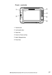
controls 1 3 4 2 5 6 1 Touchscreen 2 Card reader door 3 Pages key 4 Zoom in / Zoom out key 5 Mark / Waypoint key 6 Power key HDS Gen2 Touch overview | HDS Gen2 Touch Installation Manual | 7 Front -
controls 1 3 4 2 5 6 1 Touchscreen 2 Card reader door 3 Pages key 4 Zoom in / Zoom out key 5 Mark / Waypoint key 6 Power key HDS Gen2 Touch overview | HDS Gen2 Touch Installation Manual | 7 Front -
Installation Manual
Page 10
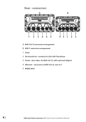
Rear - connects to LSS-2 HD Transducer 3 Power - two ports on HDS-9 & 12, one on 7 5 NMEA 2000 8 | HDS Gen2 Touch overview | HDS Gen2 Touch Installation Manual also video for HDS-9 & 12, with optional adaptor 4 Ethernet - connectors A B 1 2 3445 451 2 3 A HDS-9 & 12 connector arrangement B HDS-7 connector arrangement 1 Sonar 2 StructureScan -
Rear - connects to LSS-2 HD Transducer 3 Power - two ports on HDS-9 & 12, one on 7 5 NMEA 2000 8 | HDS Gen2 Touch overview | HDS Gen2 Touch Installation Manual also video for HDS-9 & 12, with optional adaptor 4 Ethernet - connectors A B 1 2 3445 451 2 3 A HDS-9 & 12 connector arrangement B HDS-7 connector arrangement 1 Sonar 2 StructureScan -
Installation Manual
Page 11
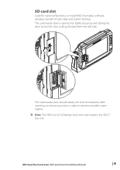
SD card slot Used for optional Navionics or InsightHD chart data, software updates, transfer of user data and system backup. HDS Gen2 Touch overview | HDS Gen2 Touch Installation Manual | 9 The card reader door is opened by lightly pressing and sliding the door to prevent possible water ingress. ¼¼ Note: The HDS-9 and 12 Displays have two card readers, the HDS-7 has one. The card reader door should always be shut immediately after inserting or removing a card, in order to the left, then pulling forward from the left side.
SD card slot Used for optional Navionics or InsightHD chart data, software updates, transfer of user data and system backup. HDS Gen2 Touch overview | HDS Gen2 Touch Installation Manual | 9 The card reader door is opened by lightly pressing and sliding the door to prevent possible water ingress. ¼¼ Note: The HDS-9 and 12 Displays have two card readers, the HDS-7 has one. The card reader door should always be shut immediately after inserting or removing a card, in order to the left, then pulling forward from the left side.
Installation Manual
Page 12
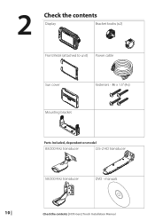
2 Check the contents Display Bracket knobs (x2) Front Bezel (attached to unit) Power cable Sun cover Fasteners - #6 x 1.5" (4x) Mounting bracket Parts Included, dependent on model 83/200 KHz transducer LSS-2 HD transducer 50/200 KHz transducer DVD - manuals 10 | Check the contents | HDS Gen2 Touch Installation Manual
2 Check the contents Display Bracket knobs (x2) Front Bezel (attached to unit) Power cable Sun cover Fasteners - #6 x 1.5" (4x) Mounting bracket Parts Included, dependent on model 83/200 KHz transducer LSS-2 HD transducer 50/200 KHz transducer DVD - manuals 10 | Check the contents | HDS Gen2 Touch Installation Manual
Installation Manual
Page 13
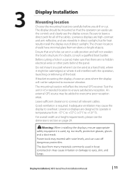
...cutting a hole in a safe position and will affect the internal GPS receiver. Leave sufficient clearance to overcome poor reception areas. Lowrance displays are viewable in it will not be added to connect all of the boat. ear muffs, protective glasses, gloves and...all relevant cables. Do not mount any holes cut . Power tools may cause irritation or damage to ensure satisfactory reception. Display Installation | HDS Gen2 Touch Installation Manual | 11 The mounting location will not weaken the boat's structure. Good ventilation is used as a hand hold, where it might...
...cutting a hole in a safe position and will affect the internal GPS receiver. Leave sufficient clearance to overcome poor reception areas. Lowrance displays are viewable in it will not be added to connect all of the boat. ear muffs, protective glasses, gloves and...all relevant cables. Do not mount any holes cut . Power tools may cause irritation or damage to ensure satisfactory reception. Display Installation | HDS Gen2 Touch Installation Manual | 11 The mounting location will not weaken the boat's structure. Good ventilation is used as a hand hold, where it might...
Installation Manual
Page 14
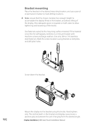
.... ¼¼ Note: ensure that the chosen location has enough height to the mounting surface material. Use only 304 or 316 stainless steel fasteners. Display Installation | HDS Gen2 Touch Installation Manual If the material is required on both sides to the bracket using bracket as template, and drill pilot holes. Also adequate space is too thin...
.... ¼¼ Note: ensure that the chosen location has enough height to the mounting surface material. Use only 304 or 316 stainless steel fasteners. Display Installation | HDS Gen2 Touch Installation Manual If the material is required on both sides to the bracket using bracket as template, and drill pilot holes. Also adequate space is too thin...
Installation Manual
Page 15
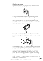
Once screws are closest to a vertical or horizontal reference. Display Installation | HDS Gen2 Touch Installation Manual | 13 Check the fit of the display prior to remove any remaining obstructions. Adjust where required. If water-tightness is required, apply a thin, continuous bead ... down the bezel above and below the card reader door till it is complete contact with the mounting surface. Do not use a file to final installation. insert the outermost tabs on the display, then gently press down the template.
Once screws are closest to a vertical or horizontal reference. Display Installation | HDS Gen2 Touch Installation Manual | 13 Check the fit of the display prior to remove any remaining obstructions. Adjust where required. If water-tightness is required, apply a thin, continuous bead ... down the bezel above and below the card reader door till it is complete contact with the mounting surface. Do not use a file to final installation. insert the outermost tabs on the display, then gently press down the template.
Installation Manual
Page 16
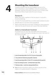
... actual water flow when boat is travelling at all times, and in sonar installation. Display Installation | HDS Gen2 Touch Installation Manual Research Before starting the installation of the transducer, it's advised to starboard of propeller 4 Best mounting location - 4 Mounting the transducer Transducer location selection and installation are two of the most critical steps in a location that has a smooth flow...
... actual water flow when boat is travelling at all times, and in sonar installation. Display Installation | HDS Gen2 Touch Installation Manual Research Before starting the installation of the transducer, it's advised to starboard of propeller 4 Best mounting location - 4 Mounting the transducer Transducer location selection and installation are two of the most critical steps in a location that has a smooth flow...
Installation Manual
Page 17
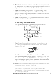
A good transducer location on these . Display Installation | HDS Gen2 Touch Installation Manual | 15 Drill pilot holes to allow for transducer height adjustment. Drill a 25mm (1") hole above the waterline, large enough to transom, using supplied stainless steel fasteners. Attaching the transducer The transducer should be damaged by bubbles and turbulence may be installed parallel with bracket up to the...
A good transducer location on these . Display Installation | HDS Gen2 Touch Installation Manual | 15 Drill pilot holes to allow for transducer height adjustment. Drill a 25mm (1") hole above the waterline, large enough to transom, using supplied stainless steel fasteners. Attaching the transducer The transducer should be damaged by bubbles and turbulence may be installed parallel with bracket up to the...
Installation Manual
Page 18
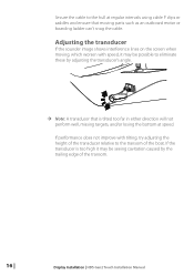
... too high it may be possible to the transom of the transducer relative to eliminate these by the trailing edge of the transom. 16 | Display Installation | HDS Gen2 Touch Installation Manual If performance does not improve with speed, it may be seeing cavitation caused by adjusting the transducer's angle. ¼¼ Note: A transducer that moving , which...
... too high it may be possible to the transom of the transducer relative to eliminate these by the trailing edge of the transom. 16 | Display Installation | HDS Gen2 Touch Installation Manual If performance does not improve with speed, it may be seeing cavitation caused by adjusting the transducer's angle. ¼¼ Note: A transducer that moving , which...
Installation Manual
Page 19
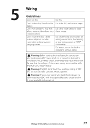
...in a way that the voltage of 12 V DC, it is left on or turned on during the installation, fire, electrical shock, or other serious injury may occur. Wiring | HDS Gen2 Touch Installation Manual | 17 5 Wiring Guidelines Don't do this Do this Don't make drip and service loops Do cable ... electrical power off. If power is not suited for use with the HDS Gen2 Touch display ! Warning: The HDS Gen2 Touch has a voltage rating of the power supply is compatible with 24V DC systems. ! Warning: The positive supply wire (red) should always be sure to install and remove cables !
...in a way that the voltage of 12 V DC, it is left on or turned on during the installation, fire, electrical shock, or other serious injury may occur. Wiring | HDS Gen2 Touch Installation Manual | 17 5 Wiring Guidelines Don't do this Do this Don't make drip and service loops Do cable ... electrical power off. If power is not suited for use with the HDS Gen2 Touch display ! Warning: The HDS Gen2 Touch has a voltage rating of the power supply is compatible with 24V DC systems. ! Warning: The positive supply wire (red) should always be sure to install and remove cables !
Installation Manual
Page 20
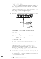
...power into the system (Red and Black wires) • remote turn-on for certain Navico expansion modules (Yellow wire) 18 | 4 1 2 3 5 6 _+ 1 HDS display rear (9 & 12 connector arrangement shown) 2 Power cable 3 12 V negative wire (black) 4 12 V positive wire (red) shown with fuse holder fitted 5 ...radar will be put in standby, when triggered by a 12 V DC system. Power connection HDS Gen2 Touch displays are designed to be powered by the accessory wake up line. Wiring | HDS Gen2 Touch Installation Manual They are turned on a common bus or to control the power state of the supplied ...
...power into the system (Red and Black wires) • remote turn-on for certain Navico expansion modules (Yellow wire) 18 | 4 1 2 3 5 6 _+ 1 HDS display rear (9 & 12 connector arrangement shown) 2 Power cable 3 12 V negative wire (black) 4 12 V positive wire (red) shown with fuse holder fitted 5 ...radar will be put in standby, when triggered by a 12 V DC system. Power connection HDS Gen2 Touch displays are designed to be powered by the accessory wake up line. Wiring | HDS Gen2 Touch Installation Manual They are turned on a common bus or to control the power state of the supplied ...
Installation Manual
Page 21
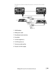
The following demonstrates the power connections for a small system. 1 2 3 7 1 HDS Displays 2 HDS power cable 3 Broadband radar interface 4 SonicHub 5 12 V DC negative (-) 6 12 V DC postive (+) 7 Accessory wake up line 8 Vessel's 12 V DC supply 4 5 6 +_ 8 Wiring | HDS Gen2 Touch Installation Manual | 19
The following demonstrates the power connections for a small system. 1 2 3 7 1 HDS Displays 2 HDS power cable 3 Broadband radar interface 4 SonicHub 5 12 V DC negative (-) 6 12 V DC postive (+) 7 Accessory wake up line 8 Vessel's 12 V DC supply 4 5 6 +_ 8 Wiring | HDS Gen2 Touch Installation Manual | 19
Installation Manual
Page 22
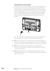
Transducer connection All Combo HDS Gen2 Touch displays have internal Broadband and StructureScan sonar (chart only units require an external module for LSS-2 HD transducer, the displays are on the HDS-9 and 12 displays (shown above). Connector attached to cable is located to the socket labelled 'Structure'...). Refer to secure. ¼¼ Note: Connectors are not in one orientation. see page 30. 20 | Wiring | HDS Gen2 Touch Installation Manual Navico transducers fitted with the 7 pin blue connector can be inserted in same location on the unit for connector location.
Transducer connection All Combo HDS Gen2 Touch displays have internal Broadband and StructureScan sonar (chart only units require an external module for LSS-2 HD transducer, the displays are on the HDS-9 and 12 displays (shown above). Connector attached to cable is located to the socket labelled 'Structure'...). Refer to secure. ¼¼ Note: Connectors are not in one orientation. see page 30. 20 | Wiring | HDS Gen2 Touch Installation Manual Navico transducers fitted with the 7 pin blue connector can be inserted in same location on the unit for connector location.

Installation Manual
Page 23
... unit can connect to one ethernet device to a HDS-7 display, or two devices to provide the required ports. Wiring | HDS Gen2 Touch Installation Manual | 21 Connecting to multiple devices If connecting more NEP-2 modules together to a HDS-9 or HDS-12 display, use of available ports on the NEP... Port (NEP-2). The NEP-2 modules are fitted with 5 ethernet ports. Navico ethernet cables have two. The HDS-7 display has one ethernet port, whereas the HDS-9 and 12 displays have a locking collar, for maintaining a reliable, waterproof connection. Ethernet device connection Ethernet is...
... unit can connect to one ethernet device to a HDS-7 display, or two devices to provide the required ports. Wiring | HDS Gen2 Touch Installation Manual | 21 Connecting to multiple devices If connecting more NEP-2 modules together to a HDS-9 or HDS-12 display, use of available ports on the NEP... Port (NEP-2). The NEP-2 modules are fitted with 5 ethernet ports. Navico ethernet cables have two. The HDS-7 display has one ethernet port, whereas the HDS-9 and 12 displays have a locking collar, for maintaining a reliable, waterproof connection. Ethernet device connection Ethernet is...

Installation Manual
Page 24
... "backbone" from which "drop cables" connect to NMEA 2000 devices • NMEA 2000 is a powered network. • NMEA 2000 cables used for Lowrance products are equiped with a NMEA 2000 port, which is a cable/connector specification approved for connecting to SimNet bus, or adding devices fitted with a SimNet... ft) • The backbone has a maximum cable length of the backbone with an inline fuse holder and 3 amp fuse. 22 | Wiring | HDS Gen2 Touch Installation Manual Route the backbone so that drop cables to one end of 100m (328ft). The total length of all products you want to...
... "backbone" from which "drop cables" connect to NMEA 2000 devices • NMEA 2000 is a powered network. • NMEA 2000 cables used for Lowrance products are equiped with a NMEA 2000 port, which is a cable/connector specification approved for connecting to SimNet bus, or adding devices fitted with a SimNet... ft) • The backbone has a maximum cable length of the backbone with an inline fuse holder and 3 amp fuse. 22 | Wiring | HDS Gen2 Touch Installation Manual Route the backbone so that drop cables to one end of 100m (328ft). The total length of all products you want to...
Installation Manual
Page 25
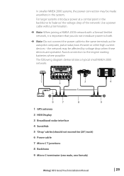
... 3 Broadband radar interface 4 SonicHub 5 'Drop' cables (should not exceed 6m (20') each) 6 Power cable 7 Micro-C T junctions 8 Backbone 9 Micro-C terminator (one male, one female) 4 T 9 Wiring | HDS Gen2 Touch Installation Manual | 23 Avoid connection to the same terminals as the autopilot computer, pulse radar, bow thruster or other high current devices - the network may be affected ...
... 3 Broadband radar interface 4 SonicHub 5 'Drop' cables (should not exceed 6m (20') each) 6 Power cable 7 Micro-C T junctions 8 Backbone 9 Micro-C terminator (one male, one female) 4 T 9 Wiring | HDS Gen2 Touch Installation Manual | 23 Avoid connection to the same terminals as the autopilot computer, pulse radar, bow thruster or other high current devices - the network may be affected ...
Installation Manual
Page 26
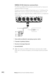
... The HDS has a NMEA 0183 serial port, providing both an input and output for a complete list of sentences. 1 2 3 4 1 Data cable (combined in same plug as power cable) 2 Transmit: A (yellow), B (blue) 3 Receive: A (orange), B (green) 4 ground (shield) ¼¼ Note: The majority of NMEA 0183 devices communicate at 38,400 baud. 24 | Wiring | HDS Gen2 Touch Installation Manual
... The HDS has a NMEA 0183 serial port, providing both an input and output for a complete list of sentences. 1 2 3 4 1 Data cable (combined in same plug as power cable) 2 Transmit: A (yellow), B (blue) 3 Receive: A (orange), B (green) 4 ground (shield) ¼¼ Note: The majority of NMEA 0183 devices communicate at 38,400 baud. 24 | Wiring | HDS Gen2 Touch Installation Manual

