

Installation Manual
Page 3
Regulatory statements This equipment is intended for observing safe boating practices. Preface | ELITE Ti Installation Manual 3 It is the owner's sole responsibility to install and use in a manner that will be the official version of ...USA, and countries of the E.U. Please contact your unit or system: lowrance.com. Copyright Copyright © 2016 Navico Holding AS. This manual represents the product as a separate document. and E.E.A. Governing Language: This statement, any instruction manuals, user guides and other information relating to the product (Documentation) may...
Regulatory statements This equipment is intended for observing safe boating practices. Preface | ELITE Ti Installation Manual 3 It is the owner's sole responsibility to install and use in a manner that will be the official version of ...USA, and countries of the E.U. Please contact your unit or system: lowrance.com. Copyright Copyright © 2016 Navico Holding AS. This manual represents the product as a separate document. and E.E.A. Governing Language: This statement, any instruction manuals, user guides and other information relating to the product (Documentation) may...

Installation Manual
Page 4
...If this device must accept any changes or modifications not expressly approved by turning the equipment off 4 Preface | ELITE Ti Installation Manual This equipment complies with the instructions, may cause harmful interference to radio communications. Operation is subject to the following... Industry Canada IC RSS-GEN, Sec 7.1.3 Warning Statement- (Required for compliance could void the user's authority to the following website: lowrance.com. Warning The user is no guarantee that may not cause harmful interference, and (2) this device must accept any interference, including ...
...If this device must accept any changes or modifications not expressly approved by turning the equipment off 4 Preface | ELITE Ti Installation Manual This equipment complies with the instructions, may cause harmful interference to radio communications. Operation is subject to the following... Industry Canada IC RSS-GEN, Sec 7.1.3 Warning Statement- (Required for compliance could void the user's authority to the following website: lowrance.com. Warning The user is no guarantee that may not cause harmful interference, and (2) this device must accept any interference, including ...

Installation Manual
Page 5
... - Portugal RO - Iceland IE - Belgium BG - Hungary IS - Malta NL - Norway PL - Denmark EE - Ireland IT - Lithuania LU - France DE - Cyprus CZ - Slovak Republic Preface | ELITE Ti Installation Manual 5
... - Portugal RO - Iceland IE - Belgium BG - Hungary IS - Malta NL - Norway PL - Denmark EE - Ireland IT - Lithuania LU - France DE - Cyprus CZ - Slovak Republic Preface | ELITE Ti Installation Manual 5
Installation Manual
Page 6
...) • StructureMap™ (StructureMap) • StructureScan® (StructureScan) • StructureScan® HD (StructureScan HD) 6 Preface | ELITE Ti Installation Manual Copyright© 2012 Fishing Hot Spots. Spain SE - Bluetooth® is a trademark of Bluetooth SIG, Inc. United Kingdom Trademarks Lowrance® and Navico® are registered trademarks of Fishing Hot Spots Inc. Fishing Hot Spots...
...) • StructureMap™ (StructureMap) • StructureScan® (StructureScan) • StructureScan® HD (StructureScan HD) 6 Preface | ELITE Ti Installation Manual Copyright© 2012 Fishing Hot Spots. Spain SE - Bluetooth® is a trademark of Bluetooth SIG, Inc. United Kingdom Trademarks Lowrance® and Navico® are registered trademarks of Fishing Hot Spots Inc. Fishing Hot Spots...
Installation Manual
Page 7
Preface | ELITE Ti Installation Manual 7 Important text that requires special attention from the reader is necessary to warn personnel that they should proceed carefully to prevent risk of injury and/or damage to a comment or some important information. Warning: Used when it is emphasized as follows: Ú Note: Used to draw the reader's attention to equipment/ personnel. About this manual This manual is a reference guide for installing the ELITE Ti.
Preface | ELITE Ti Installation Manual 7 Important text that requires special attention from the reader is necessary to warn personnel that they should proceed carefully to prevent risk of injury and/or damage to a comment or some important information. Warning: Used when it is emphasized as follows: Ú Note: Used to draw the reader's attention to equipment/ personnel. About this manual This manual is a reference guide for installing the ELITE Ti.

Installation Manual
Page 8
8 Preface | ELITE Ti Installation Manual
8 Preface | ELITE Ti Installation Manual
Installation Manual
Page 9
... Device list 34 Diagnostics 36 Damping 36 Sonar setup 38 StructureScan 38 Autopilot setup 38 Fuel setup 41 Wireless setup 44 Bluetooth wireless technology Contents | ELITE Ti Installation Manual 9
... Device list 34 Diagnostics 36 Damping 36 Sonar setup 38 StructureScan 38 Autopilot setup 38 Fuel setup 41 Wireless setup 44 Bluetooth wireless technology Contents | ELITE Ti Installation Manual 9
Installation Manual
Page 10
44 NMEA 2000 setup 45 NMEA 0183 setup 46 Touchscreen calibration 47 Software updates and data backup 50 Accessories 50 NMEA 2000 50 ELITE Ti accessories 51 Sonar accessories 52 Supported data 52 NMEA 2000 compliant PGN List 56 NMEA 0183 supported sentences 58 Specifications 60 Dimensional drawings 60 ELITE-5Ti Dimensional drawings 60 ELITE-7Ti Dimensional drawings 10 Contents | ELITE Ti Installation Manual
44 NMEA 2000 setup 45 NMEA 0183 setup 46 Touchscreen calibration 47 Software updates and data backup 50 Accessories 50 NMEA 2000 50 ELITE Ti accessories 51 Sonar accessories 52 Supported data 52 NMEA 2000 compliant PGN List 56 NMEA 0183 supported sentences 58 Specifications 60 Dimensional drawings 60 ELITE-5Ti Dimensional drawings 60 ELITE-7Ti Dimensional drawings 10 Contents | ELITE Ti Installation Manual

Installation Manual
Page 11
Included only with units that do not include transducers. 5 Fuse holder (ATC blade) 6 Quick release mounting bracket 7 Fuse (3 amp) 8 Quick release mounting bracket screws (4 x #10 x 3/4 PN HD SS screws) 9 Bracket locking bolt and knob. (ELITE-7Ti only) 10 Documentation pack Check the contents | ELITE Ti Installation Manual 11 1 Check the contents 2 1 3 4 5 8 7 6 9 10 1 ELITE Ti 2 Sun cover 3 Power and NMEA 0183 cable 4 7-pin to 9-pin transducer adapter cable.
Included only with units that do not include transducers. 5 Fuse holder (ATC blade) 6 Quick release mounting bracket 7 Fuse (3 amp) 8 Quick release mounting bracket screws (4 x #10 x 3/4 PN HD SS screws) 9 Bracket locking bolt and knob. (ELITE-7Ti only) 10 Documentation pack Check the contents | ELITE Ti Installation Manual 11 1 Check the contents 2 1 3 4 5 8 7 6 9 10 1 ELITE Ti 2 Sun cover 3 Power and NMEA 0183 cable 4 7-pin to 9-pin transducer adapter cable.

Installation Manual
Page 12
The ELITE-7Ti can send and receive data via NMEA 0183. The system also supports charts from Navico including Insight Genesis. The unit is intended for 12 V ... of available charts, visit gofreeshop.com, c-map.jeppesen.com, or navionics.com. The ELITE-5Ti and ELITE-7Ti can network over NMEA 2000, this allows access to the vessel with the supplied mounting bracket, or panel mounted on the dash. 2 12 Overview The unit has a built-in (combined press = MOB) Overview | ELITE Ti Installation Manual
The ELITE-7Ti can send and receive data via NMEA 0183. The system also supports charts from Navico including Insight Genesis. The unit is intended for 12 V ... of available charts, visit gofreeshop.com, c-map.jeppesen.com, or navionics.com. The ELITE-5Ti and ELITE-7Ti can network over NMEA 2000, this allows access to the vessel with the supplied mounting bracket, or panel mounted on the dash. 2 12 Overview The unit has a built-in (combined press = MOB) Overview | ELITE Ti Installation Manual

Installation Manual
Page 13
Press once to turn the unit ON/OFF. CHIRP, Broadband, DownScan and SideScan imaging 2 Power (12 V supply input) and NMEA 0183 Overview | ELITE Ti Installation Manual 13 4 New waypoint (long press = Find dialogue) 5 Power button Press and hold to display the System Controls dialog. 6 Card reader (behind logo) Rear connections ELITE-5Ti rear connections LTW 1 2 1 Sonar -
Press once to turn the unit ON/OFF. CHIRP, Broadband, DownScan and SideScan imaging 2 Power (12 V supply input) and NMEA 0183 Overview | ELITE Ti Installation Manual 13 4 New waypoint (long press = Find dialogue) 5 Power button Press and hold to display the System Controls dialog. 6 Card reader (behind logo) Rear connections ELITE-5Ti rear connections LTW 1 2 1 Sonar -

Installation Manual
Page 14
data input / output 3 Sonar - The memory card can be used for attaching a microSD memory card. The card reader door is opened by flipping back the logo and pulling the rubber cover open. 14 Overview | ELITE Ti Installation Manual ELITE-7Ti rear connections 12 3 1 Power (12 V supply input) and NMEA 0183 2 NMEA 2000 - CHIRP, Broadband, DownScan and SideScan imaging Card reader Used for detailed chart data, software updates, transfer of user data, and system backup.
data input / output 3 Sonar - The memory card can be used for attaching a microSD memory card. The card reader door is opened by flipping back the logo and pulling the rubber cover open. 14 Overview | ELITE Ti Installation Manual ELITE-7Ti rear connections 12 3 1 Power (12 V supply input) and NMEA 0183 2 NMEA 2000 - CHIRP, Broadband, DownScan and SideScan imaging Card reader Used for detailed chart data, software updates, transfer of user data, and system backup.

Installation Manual
Page 15
The card reader door should always be securely shut immediately after inserting or removing a card, in order to prevent possible water ingress. Overview | ELITE Ti Installation Manual 15
The card reader door should always be securely shut immediately after inserting or removing a card, in order to prevent possible water ingress. Overview | ELITE Ti Installation Manual 15
Installation Manual
Page 16
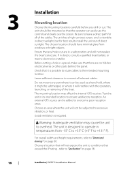
...° F). The unit should have minimal glare from -15° C to +55° C (+5° F to "Dimensional drawings" on page 58. The unit is required. Installation | ELITE Ti Installation Manual
...° F). The unit should have minimal glare from -15° C to +55° C (+5° F to "Dimensional drawings" on page 58. The unit is required. Installation | ELITE Ti Installation Manual

Installation Manual
Page 17
... the bracket, allows tilting of the unit and connecting cables in boat construction may exceed safe noise levels, and can cast off dangerous projectiles. Installation | ELITE Ti Installation Manual 17 Quick release bracket mounting 1. Use only 304 or 316 stainless steel fasteners. 3. The dust from many materials commonly used . Mark the screw locations...
... the bracket, allows tilting of the unit and connecting cables in boat construction may exceed safe noise levels, and can cast off dangerous projectiles. Installation | ELITE Ti Installation Manual 17 Quick release bracket mounting 1. Use only 304 or 316 stainless steel fasteners. 3. The dust from many materials commonly used . Mark the screw locations...

Installation Manual
Page 18
For ELITE-7Ti only, set the desired angle and then insert the locking bolt and knob. 5. Tilt the unit to stop angle movement 18 Installation | ELITE Ti Installation Manual Tighten to the desired position angle. 6.
For ELITE-7Ti only, set the desired angle and then insert the locking bolt and knob. 5. Tilt the unit to stop angle movement 18 Installation | ELITE Ti Installation Manual Tighten to the desired position angle. 6.
Installation Manual
Page 19
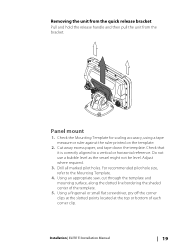
... template. Adjust where required. 3. Check the Mounting Template for scaling accuracy, using a tape measure or ruler against the ruler printed on the template. 2. Installation | ELITE Ti Installation Manual 19 Using a fingernail or small flat screwdriver, pry off the corner clips at the slotted points located at the top or bottom of the template...
... template. Adjust where required. 3. Check the Mounting Template for scaling accuracy, using a tape measure or ruler against the ruler printed on the template. 2. Installation | ELITE Ti Installation Manual 19 Using a fingernail or small flat screwdriver, pry off the corner clips at the slotted points located at the top or bottom of the template...
Installation Manual
Page 20
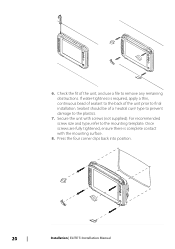
.... 7. 6. Sealant should be of a 'neutral cure' type to prevent damage to the mounting template. Press the four corner clips back into position. 20 Installation | ELITE Ti Installation Manual Check the fit of the unit prior to remove any remaining obstructions. Once screws are fully tightened, ensure there is required, apply a thin, continuous bead...
.... 7. 6. Sealant should be of a 'neutral cure' type to prevent damage to the mounting template. Press the four corner clips back into position. 20 Installation | ELITE Ti Installation Manual Check the fit of the unit prior to remove any remaining obstructions. Once screws are fully tightened, ensure there is required, apply a thin, continuous bead...

Installation Manual
Page 21
Installation | ELITE Ti Installation Manual 21
Installation | ELITE Ti Installation Manual 21
Installation Manual
Page 22
... out if the boat builder has a recommended installation location • Establish the direction of rotation of the vessel as possible. 22 Mounting the transducer | ELITE Ti Installation Manual To function properly the transducer must be in your vessel. Separate instructions for mounting a transom mount skimmer transducer. Transducer location selection and installation are provided...
... out if the boat builder has a recommended installation location • Establish the direction of rotation of the vessel as possible. 22 Mounting the transducer | ELITE Ti Installation Manual To function properly the transducer must be in your vessel. Separate instructions for mounting a transom mount skimmer transducer. Transducer location selection and installation are provided...

