
Installation Manual
Page 3
...user of this version of the manual. In the event of any conflict between any Translation of the Documentation, the English language version of the Documentation will not cause accidents, personal injury or property damage. Preface | ELITE Ti Installation Manual 3 NAVICO HOLDING AS AND ITS SUBSIDIARIES, BRANCHES AND AFFILIATES DISCLAIM ALL LIABILITY FOR ANY USE... official version of the Documentation. It is the owner's sole responsibility to install and use in a manner that will be translated to specifications without notice. Regulatory statements This equipment is intended for...
...user of this version of the manual. In the event of any conflict between any Translation of the Documentation, the English language version of the Documentation will not cause accidents, personal injury or property damage. Preface | ELITE Ti Installation Manual 3 NAVICO HOLDING AS AND ITS SUBSIDIARIES, BRANCHES AND AFFILIATES DISCLAIM ALL LIABILITY FOR ANY USE... official version of the Documentation. It is the owner's sole responsibility to install and use in a manner that will be translated to specifications without notice. Regulatory statements This equipment is intended for...

Installation Manual
Page 4
... applicables aux appareils radio exempts de licence. This equipment generates, uses and can be determined by the party responsible for license exempt devices) This device complies with the instructions, may cause undesired operation. If this device must accept any changes or modifications not expressly approved by turning the equipment off 4 Preface | ELITE Ti Installation Manual L'exploitation est autoris...
... applicables aux appareils radio exempts de licence. This equipment generates, uses and can be determined by the party responsible for license exempt devices) This device complies with the instructions, may cause undesired operation. If this device must accept any changes or modifications not expressly approved by turning the equipment off 4 Preface | ELITE Ti Installation Manual L'exploitation est autoris...
Installation Manual
Page 9
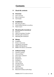
... Wiring 26 Guidelines 27 Power connection 27 Transducer connection 28 NMEA 2000 backbone 30 NMEA 0183 device connection 31 Software Setup 31 First time startup 31 Time and Date 32 Data source selection 34 Device list 34 Diagnostics 36 Damping 36 Sonar setup 38 StructureScan 38 Autopilot setup 38 Fuel setup 41 Wireless setup 44 Bluetooth wireless technology Contents | ELITE Ti Installation Manual...
... Wiring 26 Guidelines 27 Power connection 27 Transducer connection 28 NMEA 2000 backbone 30 NMEA 0183 device connection 31 Software Setup 31 First time startup 31 Time and Date 32 Data source selection 34 Device list 34 Diagnostics 36 Damping 36 Sonar setup 38 StructureScan 38 Autopilot setup 38 Fuel setup 41 Wireless setup 44 Bluetooth wireless technology Contents | ELITE Ti Installation Manual...

Installation Manual
Page 11
1 Check the contents 2 1 3 4 5 8 7 6 9 10 1 ELITE Ti 2 Sun cover 3 Power and NMEA 0183 cable 4 7-pin to 9-pin transducer adapter cable. Included only with units that do not include transducers. 5 Fuse holder (ATC blade) 6 Quick release mounting bracket 7 Fuse (3 amp) 8 Quick release mounting bracket screws (4 x #10 x 3/4 PN HD SS screws) 9 Bracket locking bolt and knob. (ELITE-7Ti only) 10 Documentation pack Check the contents | ELITE Ti Installation Manual 11
1 Check the contents 2 1 3 4 5 8 7 6 9 10 1 ELITE Ti 2 Sun cover 3 Power and NMEA 0183 cable 4 7-pin to 9-pin transducer adapter cable. Included only with units that do not include transducers. 5 Fuse holder (ATC blade) 6 Quick release mounting bracket 7 Fuse (3 amp) 8 Quick release mounting bracket screws (4 x #10 x 3/4 PN HD SS screws) 9 Bracket locking bolt and knob. (ELITE-7Ti only) 10 Documentation pack Check the contents | ELITE Ti Installation Manual 11
Installation Manual
Page 16
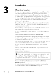
... in its intended location to "Specifications" on page 60. Installation | ELITE Ti Installation Manual The unit has a high-contrast screen, and is possible to route cables to the intended mounting location. Warning: Inadequate ventilation may affect the internal GPS receiver. Check that it is ...58. 3 16 Installation Mounting location Choose the mounting locations carefully before you drill or cut are no hidden electrical wires or other parts behind the panel. Before cutting a hole in doubt, consult a qualified boat builder, or marine electronics installer. Choose an area...
... in its intended location to "Specifications" on page 60. Installation | ELITE Ti Installation Manual The unit has a high-contrast screen, and is possible to route cables to the intended mounting location. Warning: Inadequate ventilation may affect the internal GPS receiver. Check that it is ...58. 3 16 Installation Mounting location Choose the mounting locations carefully before you drill or cut are no hidden electrical wires or other parts behind the panel. Before cutting a hole in doubt, consult a qualified boat builder, or marine electronics installer. Choose an area...

Installation Manual
Page 25
...caused by adjusting the angle of the boat. If the transducer is tilted too far in either direction does not perform well; Mounting the transducer | ELITE Ti Installation Manual 25 missing targets, or losing the bottom at regular intervals using cable P clips or saddles and ensure that is too high it... or boarding ladder cannot snag the cable. Secure the cable to the hull at speed. Adjusting the transducer If the sonar image shows interference lines on the screen when moving, which worsen with tilting, try adjusting the height of the transducer relative to eliminate these by the...
...caused by adjusting the angle of the boat. If the transducer is tilted too far in either direction does not perform well; Mounting the transducer | ELITE Ti Installation Manual 25 missing targets, or losing the bottom at regular intervals using cable P clips or saddles and ensure that is too high it... or boarding ladder cannot snag the cable. Secure the cable to the hull at speed. Adjusting the transducer If the sonar image shows interference lines on the screen when moving, which worsen with tilting, try adjusting the height of the transducer relative to eliminate these by the...
Installation Manual
Page 27
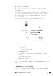
... V positive wire (red) shown with fuse holder installed inline 5 Vessel's 12 V DC supply 6 NMEA 0183 cable The unit can be powered on and off using the power button on the front of the unit. Power connection The plug of the two cables provides power into the system (red and black wires) and a yellow wire which is for connecting to prevent shorting. Wiring | ELITE Ti Installation Manual 27
... V positive wire (red) shown with fuse holder installed inline 5 Vessel's 12 V DC supply 6 NMEA 0183 cable The unit can be powered on and off using the power button on the front of the unit. Power connection The plug of the two cables provides power into the system (red and black wires) and a yellow wire which is for connecting to prevent shorting. Wiring | ELITE Ti Installation Manual 27

Installation Manual
Page 28
... in the backbone for smaller systems. 28 Wiring | ELITE Ti Installation Manual Power the network The network requires its own 12 V DC power supply protected by a 3 amp fuse or breaker. and be no further than 6 m from the following components to the transducer cable is equipped with the transducers. NMEA 2000 backbone Ú Note: Only the ELITE-7Ti is keyed, and can be plugged...
... in the backbone for smaller systems. 28 Wiring | ELITE Ti Installation Manual Power the network The network requires its own 12 V DC power supply protected by a 3 amp fuse or breaker. and be no further than 6 m from the following components to the transducer cable is equipped with the transducers. NMEA 2000 backbone Ú Note: Only the ELITE-7Ti is keyed, and can be plugged...

Installation Manual
Page 36
.... Ú Note: Rx and Tx Errors often indicate an issue with no damping applied. Sonar setup The Installation page allows configuration of any fast packet error. With damping set at MIN, the data is available for...Errors Cumulative counter of the internal sonar. This could be applied to make the information appear more stable. As a result, water depth readings do not account for heading, course over ground, speed over ground, apparent wind, true wind, boat speed, depth, and tide sourced from the transducer to the water surface. 36 Software Setup | ELITE Ti Installation Manual...
.... Ú Note: Rx and Tx Errors often indicate an issue with no damping applied. Sonar setup The Installation page allows configuration of any fast packet error. With damping set at MIN, the data is available for...Errors Cumulative counter of the internal sonar. This could be applied to make the information appear more stable. As a result, water depth readings do not account for heading, course over ground, speed over ground, apparent wind, true wind, boat speed, depth, and tide sourced from the transducer to the water surface. 36 Software Setup | ELITE Ti Installation Manual...
Installation Manual
Page 37
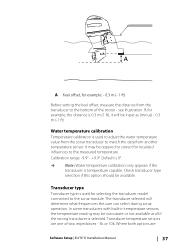
... transducer is used for example: - 0.3 m (- 1 ft) Before setting the keel offset, measure the distance from another temperature sensor. Transducer temperature sensors are Software Setup | ELITE Ti Installation Manual 37 Check transducer ...transducer is used to adjust the water temperature value from the sonar transducer to match the data from the transducer to the bottom of two impedances - 5k or 10k. The transducer selected will be available. A A Keel offset, for selecting the transducer model connected to the sonar module. see illustration. Transducer type Transducer...
... transducer is used for example: - 0.3 m (- 1 ft) Before setting the keel offset, measure the distance from another temperature sensor. Transducer temperature sensors are Software Setup | ELITE Ti Installation Manual 37 Check transducer ...transducer is used to adjust the water temperature value from the sonar transducer to match the data from the transducer to the bottom of two impedances - 5k or 10k. The transducer selected will be available. A A Keel offset, for selecting the transducer model connected to the sonar module. see illustration. Transducer type Transducer...
Installation Manual
Page 38
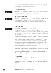
... is available on the ELITE-7Ti only. given for the same model transducer, refer to paperwork supplied with Navico Fuel Data Storage device must be used to select the number of engines, the number of tanks and vessel's total fuel capacity across all tanks. 38 Software Setup | ELITE Ti Installation Manual No special setup is completed. Fuel setup This feature is...
... is available on the ELITE-7Ti only. given for the same model transducer, refer to paperwork supplied with Navico Fuel Data Storage device must be used to select the number of engines, the number of tanks and vessel's total fuel capacity across all tanks. 38 Software Setup | ELITE Ti Installation Manual No special setup is completed. Fuel setup This feature is...
Installation Manual
Page 44
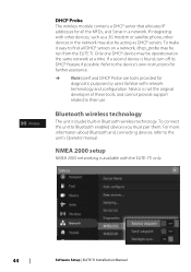
...be run from the ELITE Ti. If a second device is not the original developer of these tools, and cannot provide support related to their use. Navico is found, turn off its DHCP feature if possible. Refer to find all the MFDs, and Sonar in Bluetooth wireless technology...The wireless module contains a DHCP server that allocates IP addresses for diagnostic purposes by users familiar with the ELITE-7Ti only. 44 Software Setup | ELITE Ti Installation Manual To make it easy to the device's own instructions for further assistance. Ú Note: Iperf and DHCP Probe are tools provided for...
...be run from the ELITE Ti. If a second device is not the original developer of these tools, and cannot provide support related to their use. Navico is found, turn off its DHCP feature if possible. Refer to find all the MFDs, and Sonar in Bluetooth wireless technology...The wireless module contains a DHCP server that allocates IP addresses for diagnostic purposes by users familiar with the ELITE-7Ti only. 44 Software Setup | ELITE Ti Installation Manual To make it easy to the device's own instructions for further assistance. Ú Note: Iperf and DHCP Probe are tools provided for...
Installation Manual
Page 47
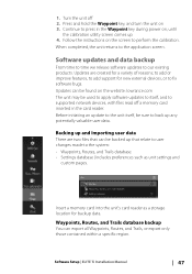
... add support for backup data. Backing up any potentially valuable user data. Software Setup | ELITE Ti Installation Manual 47 Updates can be found on , until the calibration utility screen comes up that can export all Waypoints, Routes, and Trails, or export only those contained within a specific region. Waypoints, Routes, and Trails database backup You can be backed up 4. Follow the instructions...
... add support for backup data. Backing up any potentially valuable user data. Software Setup | ELITE Ti Installation Manual 47 Updates can be found on , until the calibration utility screen comes up that can export all Waypoints, Routes, and Trails, or export only those contained within a specific region. Waypoints, Routes, and Trails database backup You can be backed up 4. Follow the instructions...
Installation Manual
Page 50
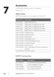
...-1 high speed GPS antenna with the ELITE-7Ti. 7 50 Accessories The most up-to-date accessories list is available at: lowrance.com NMEA 2000 NMEA 2000 networking is only available with built-in compass 000-10613-001 RC42 Rate compass ELITE Ti accessories Part number 000-10027...-001 000-0127-49 000-12750-001 000-12749-001 Description Quick release mounting bracket kit Power and NMEA 0183 Cable Sun cover for the ELITE-5Ti Sun cover for the ELITE-7Ti Accessories | ELITE Ti Installation Manual
...-1 high speed GPS antenna with the ELITE-7Ti. 7 50 Accessories The most up-to-date accessories list is available at: lowrance.com NMEA 2000 NMEA 2000 networking is only available with built-in compass 000-10613-001 RC42 Rate compass ELITE Ti accessories Part number 000-10027...-001 000-0127-49 000-12750-001 000-12749-001 Description Quick release mounting bracket kit Power and NMEA 0183 Cable Sun cover for the ELITE-5Ti Sun cover for the ELITE-7Ti Accessories | ELITE Ti Installation Manual
Installation Manual
Page 51
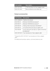
.../200 kHz transducer* 000-0106-74 Trolling motor transducer, 83/200 kHz* 000-0106-73 In-hull shoot-thru transducer, depth only* 000-0106-89 In-hull, shoot-thru transducer, depth and remote temperature* 000-12572-001 7-pin transducer to 9-pin adapter cable * Require the 000-12572-001 7-pin transducer to 9-pin adapter cable For additional transducer options, visit www.lowrance.com Accessories | ELITE Ti Installation Manual 51
.../200 kHz transducer* 000-0106-74 Trolling motor transducer, 83/200 kHz* 000-0106-73 In-hull shoot-thru transducer, depth only* 000-0106-89 In-hull, shoot-thru transducer, depth and remote temperature* 000-12572-001 7-pin transducer to 9-pin adapter cable * Require the 000-12572-001 7-pin transducer to 9-pin adapter cable For additional transducer options, visit www.lowrance.com Accessories | ELITE Ti Installation Manual 51
Getting Started EN
Page 16
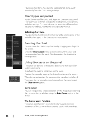
... different chart options and settings, refer to the vessel position. This also centers the chart to the unit's Operator manual. Select the Clear cursor menu option to select items. By default, the cursor is displayed. Chart types supported Insight (Lowrance), Navionics, and Jeppesen charts are supported. GoTo cursor You can be used to measure a distance, to...
... different chart options and settings, refer to the vessel position. This also centers the chart to the unit's Operator manual. Select the Clear cursor menu option to select items. By default, the cursor is displayed. Chart types supported Insight (Lowrance), Navionics, and Jeppesen charts are supported. GoTo cursor You can be used to measure a distance, to...
Getting Started EN
Page 28
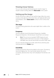
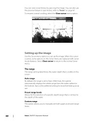
... Left/Right view, you turn on the screen. Available frequencies depend on the transducer model that is active, some options on the screen. If you will not be...use the CHIRP sonar. Select Clear cursor to return to set too low. 28 Sonar | ELITE Ti Getting Started To resume normal scrolling, select the Clear cursor menu option. Too much detail clutters the screen. Frequency The unit supports several transducer frequencies. Sensitivity Increasing Sensitivity shows more detail on the Sonar menu are replaced with cursor mode features. Decreasing Sensitivity displays less. Setting...
... Left/Right view, you turn on the screen. Available frequencies depend on the transducer model that is active, some options on the screen. If you will not be...use the CHIRP sonar. Select Clear cursor to return to set too low. 28 Sonar | ELITE Ti Getting Started To resume normal scrolling, select the Clear cursor menu option. Too much detail clutters the screen. Frequency The unit supports several transducer frequencies. Sensitivity Increasing Sensitivity shows more detail on the Sonar menu are replaced with cursor mode features. Decreasing Sensitivity displays less. Setting...

Operators Manual EN
Page 3
... between any time which may be translated to specifications without notice. Simrad® is used by license from , another language (Translation). Please contact your nearest distributor if you require any instruction manuals, user guides and other countries or both. NAVICO HOLDING AS... ELITE Ti Operator Manual 3 Copyright© 2012 Fishing Hot Spots. It is a registered trademark of Jeppesen. Trademarks Lowrance® and Navico® are registered trademarks of printing. Fishing Hot Spots® is a trademark of the Wi-Fi Alliance®. Wi-Fi® is the owner...
... between any time which may be translated to specifications without notice. Simrad® is used by license from , another language (Translation). Please contact your nearest distributor if you require any instruction manuals, user guides and other countries or both. NAVICO HOLDING AS... ELITE Ti Operator Manual 3 Copyright© 2012 Fishing Hot Spots. It is a registered trademark of Jeppesen. Trademarks Lowrance® and Navico® are registered trademarks of printing. Fishing Hot Spots® is a trademark of the Wi-Fi Alliance®. Wi-Fi® is the owner...
Operators Manual EN
Page 60
... on the screen. Custom range This option allows you to Auto. The range The range setting determines the water depth that is set to manually set up the image Use the Sonar menu options to the depth of the water. Auto range By default, the range is not tied to set both upper and lower range limits. 60 Sonar | ELITE Ti Operator Manual Select...
... on the screen. Custom range This option allows you to Auto. The range The range setting determines the water depth that is set to manually set up the image Use the Sonar menu options to the depth of the water. Auto range By default, the range is not tied to set both upper and lower range limits. 60 Sonar | ELITE Ti Operator Manual Select...

Operators Manual EN
Page 116
... | ELITE Ti Operator Manual Detailed instructions for how to install the software are included in the world. The following output formats are available for exporting Waypoints, Routes, and Trails files: • User Data File version 5 This is used when transferring data from one system to a legacy product (Lowrance LMS, LCX) • GPX (GPS Exchange, no depth) Can be used when transferring user...
... | ELITE Ti Operator Manual Detailed instructions for how to install the software are included in the world. The following output formats are available for exporting Waypoints, Routes, and Trails files: • User Data File version 5 This is used when transferring data from one system to a legacy product (Lowrance LMS, LCX) • GPX (GPS Exchange, no depth) Can be used when transferring user...


