

LA400 Manual
Page 2
...WIRING Connect the Gate Operator (Gate 1) to the Control Box Set the Bipart Delay (Model LA400-S Only) Connect the Gate Operator (Gate 2) to the Control Box (Model LA400-S Only) Junction Box (Model LA400-S Only) Connect Transformer to Control Board Earth Ground Rod Installation (Optional) Connect Batteries 1-6 1...Protection OPERATION AND MAINTENANCE Reset Button Remote Control Manual Release Maintenance TROUBLESHOOTING Basic Control Board Layout Wiring Diagram Diagnostic Codes Troubleshooting Chart REPAIR PARTS Control Box Gate Operator Arm How to Order Repair Parts WARRANTY POLICY ACCESSORIES ...
...WIRING Connect the Gate Operator (Gate 1) to the Control Box Set the Bipart Delay (Model LA400-S Only) Connect the Gate Operator (Gate 2) to the Control Box (Model LA400-S Only) Junction Box (Model LA400-S Only) Connect Transformer to Control Board Earth Ground Rod Installation (Optional) Connect Batteries 1-6 1...Protection OPERATION AND MAINTENANCE Reset Button Remote Control Manual Release Maintenance TROUBLESHOOTING Basic Control Board Layout Wiring Diagram Diagnostic Codes Troubleshooting Chart REPAIR PARTS Control Box Gate Operator Arm How to Order Repair Parts WARRANTY POLICY ACCESSORIES ...
LA400 Manual
Page 43
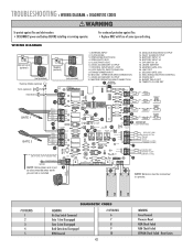
CONTROL INPUTS/EXIT LOOP 8. TRANSFORMER INPUT 10. MASTER GATE JOG 20. TROUBLESHOOTING » WIRING DIAGRAM + DIAGNOSTIC CODES To protect against fire: • Replace ONLY with fuse of same type and rating. For continued protection against fire ...green wire must 9 be disconnected when earth ground rod is installed. 16 15 NOTE: Batteries must be connected to operate. # OF BLINKS 1 2 3 4 5 DIAGNOSTIC CODES MEANING No Stop Switch Connected Gate 1 Arm Disengaged Gate 2 Arm Disengaged Both Gate Arms Disengaged RPM Reversal # OF BLINKS 6 7 8 9 10 42 MEANING Force Reversal...
CONTROL INPUTS/EXIT LOOP 8. TRANSFORMER INPUT 10. MASTER GATE JOG 20. TROUBLESHOOTING » WIRING DIAGRAM + DIAGNOSTIC CODES To protect against fire: • Replace ONLY with fuse of same type and rating. For continued protection against fire ...green wire must 9 be disconnected when earth ground rod is installed. 16 15 NOTE: Batteries must be connected to operate. # OF BLINKS 1 2 3 4 5 DIAGNOSTIC CODES MEANING No Stop Switch Connected Gate 1 Arm Disengaged Gate 2 Arm Disengaged Both Gate Arms Disengaged RPM Reversal # OF BLINKS 6 7 8 9 10 42 MEANING Force Reversal...


