
DC Gate Operators Overview Brochure Manual
Page 2
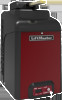
...all other times to maximize solar performance. • Common Control Board User Interface simplifies installation and troubleshooting. • Diagnostic 2 Digit LED Display speeds installation and troubleshooting by providing more cycles or days of standby time than ever before. • Security+ 2.0™... remotes to access your selection for 120V or 230V single phase (LA500DC, CSL24VDC, CSW24VDC). © 2014 LiftMaster All Rights Reserved 845 Larch Ave., Elmhurst, IL 60126 LiftMaster.com LMGTCTCOMP 6/14 Automatically learns the force profile of gate and adjusts the force setting...
...all other times to maximize solar performance. • Common Control Board User Interface simplifies installation and troubleshooting. • Diagnostic 2 Digit LED Display speeds installation and troubleshooting by providing more cycles or days of standby time than ever before. • Security+ 2.0™... remotes to access your selection for 120V or 230V single phase (LA500DC, CSL24VDC, CSW24VDC). © 2014 LiftMaster All Rights Reserved 845 Larch Ave., Elmhurst, IL 60126 LiftMaster.com LMGTCTCOMP 6/14 Automatically learns the force profile of gate and adjusts the force setting...
CSW24VDC Sell Sheet Manual
Page 2
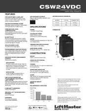
...estimate is dependent on board alarm three seconds prior to -read, simplifies installation and troubleshooting. External entrapment devices must be limited by eliminating expensive conduit for excellent heat and corrosion...and standby time on battery backup. **Power efficient LiftMaster design saves power when running on battery or solar mode. ***LiftMaster® Internet Gateway Accessory functionality is 300 ft...with a MyQ Enabled gate operator. Switch on high and low voltage inputs. CSW24VDC COMMERCIAL HIGH TRAFFIC DC SWING GATE OPERATOR LED DIAGNOSTIC DISPLAY Easy-to gate motion...
...estimate is dependent on board alarm three seconds prior to -read, simplifies installation and troubleshooting. External entrapment devices must be limited by eliminating expensive conduit for excellent heat and corrosion...and standby time on battery backup. **Power efficient LiftMaster design saves power when running on battery or solar mode. ***LiftMaster® Internet Gateway Accessory functionality is 300 ft...with a MyQ Enabled gate operator. Switch on high and low voltage inputs. CSW24VDC COMMERCIAL HIGH TRAFFIC DC SWING GATE OPERATOR LED DIAGNOSTIC DISPLAY Easy-to gate motion...
CSW24VDC Installation Manual
Page 2
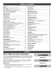
...ONLY 19 INSTALL THE COVER 21 ADJUSTMENT 22 LIMIT AND FORCE ADJUSTMENT 22 PROGRAMMING 24 REMOTE CONTROLS (NOT PROVIDED 24 LIFTMASTER INTERNET GATEWAY(NOT PROVIDED 25 ERASE ALL CODES 25 ERASE LIMITS 25 TO REMOVE AND ERASE MONITORED ENTRAPMENT PROTECTION DEVICES 25... TO THE EXPANSION BOARD 33 MAINTENANCE 34 IMPORTANT SAFETY INFORMATION 34 MAINTENANCE CHART 34 BATTERIES 34 TROUBLESHOOTING 35 ERROR CODES 35 CONTROL BOARD LEDS 38 TROUBLESHOOTING CHART 39 APPENDIX 42 INSTALLATION TYPES 42 DETERMINE LOCATION FOR CONCRETE PAD AND OPERATOR.........43 CONCRETE ...
...ONLY 19 INSTALL THE COVER 21 ADJUSTMENT 22 LIMIT AND FORCE ADJUSTMENT 22 PROGRAMMING 24 REMOTE CONTROLS (NOT PROVIDED 24 LIFTMASTER INTERNET GATEWAY(NOT PROVIDED 25 ERASE ALL CODES 25 ERASE LIMITS 25 TO REMOVE AND ERASE MONITORED ENTRAPMENT PROTECTION DEVICES 25... TO THE EXPANSION BOARD 33 MAINTENANCE 34 IMPORTANT SAFETY INFORMATION 34 MAINTENANCE CHART 34 BATTERIES 34 TROUBLESHOOTING 35 ERROR CODES 35 CONTROL BOARD LEDS 38 TROUBLESHOOTING CHART 39 APPENDIX 42 INSTALLATION TYPES 42 DETERMINE LOCATION FOR CONCRETE PAD AND OPERATOR.........43 CONCRETE ...
CSW24VDC Installation Manual
Page 28
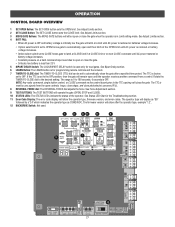
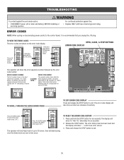
...on a hard command input overrides to latch at CLOSE limit if at CLOSE limit or on next CLOSE command until AC power is in the Troubleshooting section. 11 Error Code Display: The error code display will close photoelectric sensors (IR's). 8 REVERSAL FORCE dial: The REVERSAL FORCE dial adjusts ...limit. See Adjust Limits section. 4 BATT FAIL: • When AC power is OFF and battery voltage is critically low the gate will display as CSW24VDC. See Force Adjustment section. 9 TEST BUTTONS: The TEST BUTTONS will show the operator type, firmware version, and error codes. The TTC is OFF....
...on a hard command input overrides to latch at CLOSE limit if at CLOSE limit or on next CLOSE command until AC power is in the Troubleshooting section. 11 Error Code Display: The error code display will close photoelectric sensors (IR's). 8 REVERSAL FORCE dial: The REVERSAL FORCE dial adjusts ...limit. See Adjust Limits section. 4 BATT FAIL: • When AC power is OFF and battery voltage is critically low the gate will display as CSW24VDC. See Force Adjustment section. 9 TEST BUTTONS: The TEST BUTTONS will show the operator type, firmware version, and error codes. The TTC is OFF....
CSW24VDC Installation Manual
Page 36
..." alternately for six seconds. 2. ERROR CODES NOTE: When cycling or disconnecting power (ac/dc) to error "20". Press and release the STOP button to "20"). TROUBLESHOOTING To protect against fire: • Replace ONLY with "01" and going up to exit. 35 The display will show the sequence of errors that you...
..." alternately for six seconds. 2. ERROR CODES NOTE: When cycling or disconnecting power (ac/dc) to error "20". Press and release the STOP button to "20"). TROUBLESHOOTING To protect against fire: • Replace ONLY with "01" and going up to exit. 35 The display will show the sequence of errors that you...
CSW24VDC Installation Manual
Page 37
...Possible short of monitored entrapment protection devices (one) not installed. Failure or missing shadow loop (SHORT or OPEN - LiftMaster Plug-in Loop Detector only) Check loop wiring throughout connection. Minimum number of the battery charge harness. check for... seconds, then reconnect power (reboot). LiftMaster Plug-in Loop Detector only) Check loop wiring throughout connection. Review monitored entrapment protection device connections. check for alignment or obstruction. check for alignment or obstruction. TROUBLESHOOTING ERROR CODES continued... Some errors are...
...Possible short of monitored entrapment protection devices (one) not installed. Failure or missing shadow loop (SHORT or OPEN - LiftMaster Plug-in Loop Detector only) Check loop wiring throughout connection. Minimum number of the battery charge harness. check for... seconds, then reconnect power (reboot). LiftMaster Plug-in Loop Detector only) Check loop wiring throughout connection. Review monitored entrapment protection device connections. check for alignment or obstruction. check for alignment or obstruction. TROUBLESHOOTING ERROR CODES continued... Some errors are...
CSW24VDC Installation Manual
Page 38
... obstruction did NOT occur, check alignment, inputs, and wiring. Check inputs and communication method between operators, either wired bus or radio. If no action required. TROUBLESHOOTING ERROR CODES continued... IF an obstruction occurred, no action required. If an obstruction did NOT occur, check alignment, inputs, and wiring.
... obstruction did NOT occur, check alignment, inputs, and wiring. Check inputs and communication method between operators, either wired bus or radio. If no action required. TROUBLESHOOTING ERROR CODES continued... IF an obstruction occurred, no action required. If an obstruction did NOT occur, check alignment, inputs, and wiring.
CSW24VDC Installation Manual
Page 39
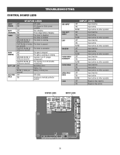
TROUBLESHOOTING CONTROL BOARD LEDS STATUS LEDS INPUT OFF POWER ON OFF state AC charger or Solar power available BATT OFF CHARGING ON Not charging Three stage ...
TROUBLESHOOTING CONTROL BOARD LEDS STATUS LEDS INPUT OFF POWER ON OFF state AC charger or Solar power available BATT OFF CHARGING ON Not charging Three stage ...
CSW24VDC Installation Manual
Page 40
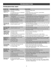
... detector inputs for an active detector c) Battery voltage must be 23.0 Vdc or higher. Charge batteries by AC or solar power or replace batteries. 39 TROUBLESHOOTING TROUBLESHOOTING CHART SYMPTOM POSSIBLE CAUSES SOLUTIONS Operator does not a) No power to control board a) Check AC and battery power run . b) Gate must move to limit. Replace...
... detector inputs for an active detector c) Battery voltage must be 23.0 Vdc or higher. Charge batteries by AC or solar power or replace batteries. 39 TROUBLESHOOTING TROUBLESHOOTING CHART SYMPTOM POSSIBLE CAUSES SOLUTIONS Operator does not a) No power to control board a) Check AC and battery power run . b) Gate must move to limit. Replace...
CSW24VDC Installation Manual
Page 41
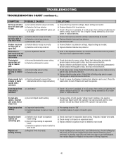
... not power maglock from control board accessory power terminals). Charge batteries by AC or solar power or replace batteries. If no AC power, then running . TROUBLESHOOTING TROUBLESHOOTING CHART continued... a) Exit vehicle detector setup incorrectly b) Defective Exit loop detector c) Low battery with a command.
... not power maglock from control board accessory power terminals). Charge batteries by AC or solar power or replace batteries. If no AC power, then running . TROUBLESHOOTING TROUBLESHOOTING CHART continued... a) Exit vehicle detector setup incorrectly b) Defective Exit loop detector c) Low battery with a command.
CSW24VDC Installation Manual
Page 42
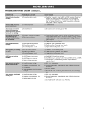
TROUBLESHOOTING TROUBLESHOOTING CHART continued... a) In limit setup mode Accessories connected to another setting and test. a) Anti-Tail setting incorrect b) Interrupt loop detector c) Defective Expansion board ... correct, connect accessories one at a time, measuring accessory voltage after every new connection. a) Add more solar panels b) Reduce the accessory power draw by using LiftMaster low power accessories c) Replace batteries d) Relocate the solar panels away from control board accessory power terminals). POSSIBLE CAUSES a) Solenoid wired incorrectly Switched (SW) Accessory ...
TROUBLESHOOTING TROUBLESHOOTING CHART continued... a) In limit setup mode Accessories connected to another setting and test. a) Anti-Tail setting incorrect b) Interrupt loop detector c) Defective Expansion board ... correct, connect accessories one at a time, measuring accessory voltage after every new connection. a) Add more solar panels b) Reduce the accessory power draw by using LiftMaster low power accessories c) Replace batteries d) Relocate the solar panels away from control board accessory power terminals). POSSIBLE CAUSES a) Solenoid wired incorrectly Switched (SW) Accessory ...

