
DC Gate Operators Overview Brochure Manual
Page 2
... installation and troubleshooting by providing more cycles or days of standby time than ever before. • Security+ 2.0™ patented multi-frequency secure radio technology virtually eliminates interference and offers 2X the range of standard remotes to access your smartphone for 120V or 230V single phase (LA500DC, CSL24VDC, CSW24VDC). © 2014 LiftMaster All Rights...
... installation and troubleshooting by providing more cycles or days of standby time than ever before. • Security+ 2.0™ patented multi-frequency secure radio technology virtually eliminates interference and offers 2X the range of standard remotes to access your smartphone for 120V or 230V single phase (LA500DC, CSL24VDC, CSW24VDC). © 2014 LiftMaster All Rights...
CSW24VDC Sell Sheet Manual
Page 2
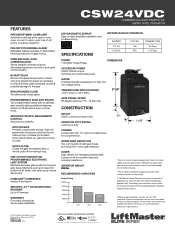
...open and close . HOMELINK® COMPATIBLE Version 4 and higher. CSW24VDC COMMERCIAL HIGH TRAFFIC DC SWING GATE OPERATOR LED DIAGNOSTIC DISPLAY Easy-to...Two programmable relays with UL 325 standards. Switch on battery or solar mode. ***LiftMaster® Internet Gateway Accessory functionality is 300 ft. CONSTRUCTION MOTOR 24VDC continuous-duty ...WARRANTY Five years commercial. TEMPERATURE SPECIFICATIONS -40°F (-40C) to -read, simplifies installation and troubleshooting. COVER High-density, UV-resistant polycarbonate 2-piece cover for dual-gate communication. OPERATOR WEIGHT 206 ...
...open and close . HOMELINK® COMPATIBLE Version 4 and higher. CSW24VDC COMMERCIAL HIGH TRAFFIC DC SWING GATE OPERATOR LED DIAGNOSTIC DISPLAY Easy-to...Two programmable relays with UL 325 standards. Switch on battery or solar mode. ***LiftMaster® Internet Gateway Accessory functionality is 300 ft. CONSTRUCTION MOTOR 24VDC continuous-duty ...WARRANTY Five years commercial. TEMPERATURE SPECIFICATIONS -40°F (-40C) to -read, simplifies installation and troubleshooting. COVER High-density, UV-resistant polycarbonate 2-piece cover for dual-gate communication. OPERATOR WEIGHT 206 ...
CSW24VDC Installation Manual
Page 2
...ONLY 19 INSTALL THE COVER 21 ADJUSTMENT 22 LIMIT AND FORCE ADJUSTMENT 22 PROGRAMMING 24 REMOTE CONTROLS (NOT PROVIDED 24 LIFTMASTER INTERNET GATEWAY(NOT PROVIDED 25 ERASE ALL CODES 25 ERASE LIMITS 25 TO REMOVE AND ERASE MONITORED ENTRAPMENT PROTECTION DEVICES 25... TO THE EXPANSION BOARD 33 MAINTENANCE 34 IMPORTANT SAFETY INFORMATION 34 MAINTENANCE CHART 34 BATTERIES 34 TROUBLESHOOTING 35 ERROR CODES 35 CONTROL BOARD LEDS 38 TROUBLESHOOTING CHART 39 APPENDIX 42 INSTALLATION TYPES 42 DETERMINE LOCATION FOR CONCRETE PAD AND OPERATOR.........43 CONCRETE ...
...ONLY 19 INSTALL THE COVER 21 ADJUSTMENT 22 LIMIT AND FORCE ADJUSTMENT 22 PROGRAMMING 24 REMOTE CONTROLS (NOT PROVIDED 24 LIFTMASTER INTERNET GATEWAY(NOT PROVIDED 25 ERASE ALL CODES 25 ERASE LIMITS 25 TO REMOVE AND ERASE MONITORED ENTRAPMENT PROTECTION DEVICES 25... TO THE EXPANSION BOARD 33 MAINTENANCE 34 IMPORTANT SAFETY INFORMATION 34 MAINTENANCE CHART 34 BATTERIES 34 TROUBLESHOOTING 35 ERROR CODES 35 CONTROL BOARD LEDS 38 TROUBLESHOOTING CHART 39 APPENDIX 42 INSTALLATION TYPES 42 DETERMINE LOCATION FOR CONCRETE PAD AND OPERATOR.........43 CONCRETE ...
CSW24VDC Installation Manual
Page 28
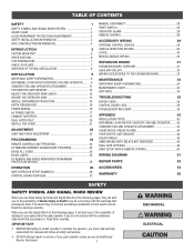
... the status of the operator. The TTC is 0 to OFF. The firmware version will close the gate when the operator is in the Troubleshooting section. 11 Error Code Display: The error code display will latch at a limit until AC power is restored or batteries voltage increases. •... will show the operator type, firmware version, and error codes. See Force Adjustment section. 9 TEST BUTTONS: The TEST BUTTONS will display as CSW24VDC. Rotate the TIMER-TO-CLOSE dial to the desired setting. See Adjust Limits section. 3 MOVE GATE Buttons: The MOVE GATE buttons will remain...
... the status of the operator. The TTC is 0 to OFF. The firmware version will close the gate when the operator is in the Troubleshooting section. 11 Error Code Display: The error code display will latch at a limit until AC power is restored or batteries voltage increases. •... will show the operator type, firmware version, and error codes. See Force Adjustment section. 9 TEST BUTTONS: The TEST BUTTONS will display as CSW24VDC. Rotate the TIMER-TO-CLOSE dial to the desired setting. See Adjust Limits section. 3 MOVE GATE Buttons: The MOVE GATE buttons will remain...
CSW24VDC Installation Manual
Page 36
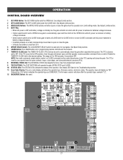
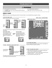
... will show "- -" until "Er" shows OPEN, CLOSE, & STOP BUTTONS ERROR CODE DISPLAY COM LINK BA The operator will only keep track of each error code. TROUBLESHOOTING To protect against fire: • Replace ONLY with "01" and going up to exit. AC & BATT FAIL BACKDRIVE TO SCROLL THROUGH THE SAVED ERROR CODES...
... will show "- -" until "Er" shows OPEN, CLOSE, & STOP BUTTONS ERROR CODE DISPLAY COM LINK BA The operator will only keep track of each error code. TROUBLESHOOTING To protect against fire: • Replace ONLY with "01" and going up to exit. AC & BATT FAIL BACKDRIVE TO SCROLL THROUGH THE SAVED ERROR CODES...
CSW24VDC Installation Manual
Page 37
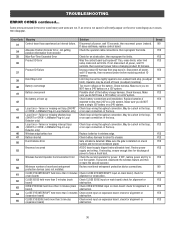
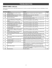
.... Saved NO YES YES YES YES NO YES YES YES YES YES YES YES YES YES YES YES NO YES YES YES YES YES 36 TROUBLESHOOTING ERROR CODES continued... Some errors are not. Product ID Error Was the control board just replaced? Disconnect all power, wait 15 seconds, then reconnect power... may be a short in the loop, or an open connection in the loop. Make sure you do NOT have a single 12V battery on main board; LiftMaster Plug-in Loop Detector only) or an open connection in the loop, or OPEN - If OFF, restore power and try to chassis Run-Distance Error...
.... Saved NO YES YES YES YES NO YES YES YES YES YES YES YES YES YES YES YES NO YES YES YES YES YES 36 TROUBLESHOOTING ERROR CODES continued... Some errors are not. Product ID Error Was the control board just replaced? Disconnect all power, wait 15 seconds, then reconnect power... may be a short in the loop, or an open connection in the loop. Make sure you do NOT have a single 12V battery on main board; LiftMaster Plug-in Loop Detector only) or an open connection in the loop, or OPEN - If OFF, restore power and try to chassis Run-Distance Error...
CSW24VDC Installation Manual
Page 38
... YES YES YES YES YES 37 check for wiring issue or obstruction. If an obstruction did NOT occur, check inputs and wiring. Check for obstruction. TROUBLESHOOTING ERROR CODES continued... If an error is engaged and free to erase the wireless communication and reprogram the two operators. IF an obstruction occurred, no...
... YES YES YES YES YES 37 check for wiring issue or obstruction. If an obstruction did NOT occur, check inputs and wiring. Check for obstruction. TROUBLESHOOTING ERROR CODES continued... If an error is engaged and free to erase the wireless communication and reprogram the two operators. IF an obstruction occurred, no...
CSW24VDC Installation Manual
Page 39
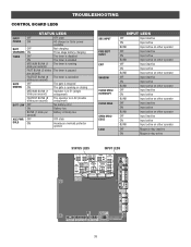
TROUBLESHOOTING CONTROL BOARD LEDS STATUS LEDS INPUT OFF POWER ON OFF state AC charger or Solar power available BATT OFF CHARGING ON Not charging Three stage ...
TROUBLESHOOTING CONTROL BOARD LEDS STATUS LEDS INPUT OFF POWER ON OFF state AC charger or Solar power available BATT OFF CHARGING ON Not charging Three stage ...
CSW24VDC Installation Manual
Page 40
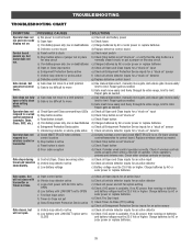
... control board Control board powers up, but will not close when setting limits. Gate does not fully open . b) Gate must be 23.0 Vdc or higher. TROUBLESHOOTING TROUBLESHOOTING CHART SYMPTOM POSSIBLE CAUSES SOLUTIONS Operator does not a) No power to control board a) Check AC and battery power run . b) Check Stop button is available. Gate...
... control board Control board powers up, but will not close when setting limits. Gate does not fully open . b) Gate must be 23.0 Vdc or higher. TROUBLESHOOTING TROUBLESHOOTING CHART SYMPTOM POSSIBLE CAUSES SOLUTIONS Operator does not a) No power to control board a) Check AC and battery power run . b) Check Stop button is available. Gate...
CSW24VDC Installation Manual
Page 41
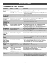
... or higher. a) Incorrect Bipart switch setting a) Expansion board setting b) Constant pressure to all inputs on batteries and battery voltage must be 23.0 Vdc or higher. TROUBLESHOOTING TROUBLESHOOTING CHART continued... a) Check photoelectric sensor wiring. a) Incorrect edge sensor wiring b) Defective edge sensor Alarm sounds for cause of both operator's Bipart switch settings. Alarm beeps...
... or higher. a) Incorrect Bipart switch setting a) Expansion board setting b) Constant pressure to all inputs on batteries and battery voltage must be 23.0 Vdc or higher. TROUBLESHOOTING TROUBLESHOOTING CHART continued... a) Check photoelectric sensor wiring. a) Incorrect edge sensor wiring b) Defective edge sensor Alarm sounds for cause of both operator's Bipart switch settings. Alarm beeps...
CSW24VDC Installation Manual
Page 42
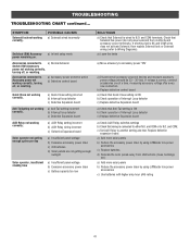
... replace Solenoid lock or Solenoid wiring (refer to N.C. a) Add more solar panels b) Reduce the accessory power draw by using LiftMaster low power accessories c) Use batteries with higher amp hour (AH) rating 41 Accessories connected to either N.O. a) Anti-Tail setting... power "ON" a) Disconnect all accessory powered devices and measure accessory power voltage (should be 23 - 30 Vdc). TROUBLESHOOTING TROUBLESHOOTING CHART continued... SYMPTOM Solenoid lock not working correctly. If voltage is correct, connect accessories one at a time, measuring accessory voltage...
... replace Solenoid lock or Solenoid wiring (refer to N.C. a) Add more solar panels b) Reduce the accessory power draw by using LiftMaster low power accessories c) Use batteries with higher amp hour (AH) rating 41 Accessories connected to either N.O. a) Anti-Tail setting... power "ON" a) Disconnect all accessory powered devices and measure accessory power voltage (should be 23 - 30 Vdc). TROUBLESHOOTING TROUBLESHOOTING CHART continued... SYMPTOM Solenoid lock not working correctly. If voltage is correct, connect accessories one at a time, measuring accessory voltage...

