
3255 Manual
Page 1
® GARAGE DOOR OPENER Models 3245 1/3 HP 3255 1/2 HP 3255-2 1/2 HP For Residential Use Only The Chamberlain Group, Inc. 845 Larch Avenue Elmhurst, Illinois 60126-1196 www.liftmaster.com Owner's Manual ■ Please read this manual and the enclosed safety materials carefully! ■ Fasten the manual near the garage door after installation. ■ The door WILL NOT...
® GARAGE DOOR OPENER Models 3245 1/3 HP 3255 1/2 HP 3255-2 1/2 HP For Residential Use Only The Chamberlain Group, Inc. 845 Larch Avenue Elmhurst, Illinois 60126-1196 www.liftmaster.com Owner's Manual ■ Please read this manual and the enclosed safety materials carefully! ■ Fasten the manual near the garage door after installation. ■ The door WILL NOT...
3255 Manual
Page 2
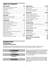
...When you see these Safety Symbols and Signal Words on the following pages, they will alert you to the possibility of damage to your garage door opener 28 Having a problem 29 Diagnostic chart 30 Programming 31-32 To add or reprogram a hand-held remote control 31 To erase all ... 33 Motor unit assembly parts 34 Accessories 35 Repair Parts and Service 36 Warranty 36 INTRODUCTION Safety Symbol and Signal Word Review This garage door opener has been designed and tested to offer safe service provided it is installed, operated, maintained and tested in strict accordance with the ...
...When you see these Safety Symbols and Signal Words on the following pages, they will alert you to the possibility of damage to your garage door opener 28 Having a problem 29 Diagnostic chart 30 Programming 31-32 To add or reprogram a hand-held remote control 31 To erase all ... 33 Motor unit assembly parts 34 Accessories 35 Repair Parts and Service 36 Warranty 36 INTRODUCTION Safety Symbol and Signal Word Review This garage door opener has been designed and tested to offer safe service provided it is installed, operated, maintained and tested in strict accordance with the ...
3255 Manual
Page 3
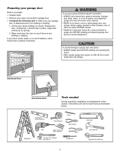
...remove ALL ropes connected to garage door BEFORE installing and operating garage door opener to see if there is out of balance. To prevent damage to garage door and opener: • ALWAYS disable locks BEFORE installing and operating the opener. • ONLY operate garage door opener at 120V, 60 Hz to... make sure your garage door Before you begin: • Disable locks. • Remove...
...remove ALL ropes connected to garage door BEFORE installing and operating garage door opener to see if there is out of balance. To prevent damage to garage door and opener: • ALWAYS disable locks BEFORE installing and operating the opener. • ONLY operate garage door opener at 120V, 60 Hz to... make sure your garage door Before you begin: • Disable locks. • Remove...
3255 Manual
Page 4
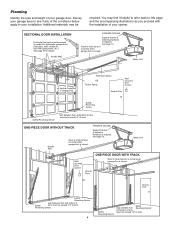
...is closed. FINISHED CEILING Support bracket & fastening hardware is required. Motor Unit Vertical Centerline of the conditions below apply to your garage area to this page and the accompanying illustrations as you proceed with glass panels, etc.). See page 12. You may be...(6 mm). Access Door Safety Reversing Sensor Gap between floor Reversing Sensor and bottom of your opener. Additional materials may find it helpful to refer back to see if any of Garage Door Extension Spring OR Torsion Spring Wallmounted Door Control Access Door --- --- -- Motor Unit ...
...is closed. FINISHED CEILING Support bracket & fastening hardware is required. Motor Unit Vertical Centerline of the conditions below apply to your garage area to this page and the accompanying illustrations as you proceed with glass panels, etc.). See page 12. You may be...(6 mm). Access Door Safety Reversing Sensor Gap between floor Reversing Sensor and bottom of your opener. Additional materials may find it helpful to refer back to see if any of Garage Door Extension Spring OR Torsion Spring Wallmounted Door Control Access Door --- --- -- Motor Unit ...
3255 Manual
Page 5
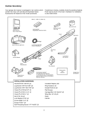
contain the motor unit and all parts illustrated below . 3245 (1), 3255 (1), 3255-2 (2) LOCK LIGHT Multi-Function Door Control Panel : SECURITY ® Single-Button Remote Control Remote Control Visor Clip Chain Sprocket Cover Styrofoam Motor Unit with 2-Conductor ... purchased. Parts may be stuck in two cartons which If anything is missing, carefully check the packing material. is also listed below . Carton Inventory Your garage door opener is packaged in the foam.
contain the motor unit and all parts illustrated below . 3245 (1), 3255 (1), 3255-2 (2) LOCK LIGHT Multi-Function Door Control Panel : SECURITY ® Single-Button Remote Control Remote Control Visor Clip Chain Sprocket Cover Styrofoam Motor Unit with 2-Conductor ... purchased. Parts may be stuck in two cartons which If anything is missing, carefully check the packing material. is also listed below . Carton Inventory Your garage door opener is packaged in the foam.
3255 Manual
Page 6
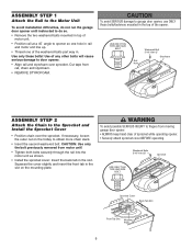
...the rail into the motor unit as shown. • Install the sprocket cover: Insert the back tab in the slot on the trolley to garage door opener, use ONLY those bolts/fasteners mounted in . Washered Bolts 5/16"-18x1/2" Sprocket USE ONLY THIS TYPE AND SIZE BOLT Sprocket Cover Back Tab ...rail, chain and styrofoam. • REMOVE STYROFOAM. ASSEMBLY STEP 1 Attach the Rail to the Motor Unit To avoid installation difficulties, do not run the garage door opener until instructed to do so. • Remove the two washered bolts mounted in top of motor unit. • Position rail at a 45˚ ...
...the rail into the motor unit as shown. • Install the sprocket cover: Insert the back tab in the slot on the trolley to garage door opener, use ONLY those bolts/fasteners mounted in . Washered Bolts 5/16"-18x1/2" Sprocket USE ONLY THIS TYPE AND SIZE BOLT Sprocket Cover Back Tab ...rail, chain and styrofoam. • REMOVE STYROFOAM. ASSEMBLY STEP 1 Attach the Rail to the Motor Unit To avoid installation difficulties, do not run the garage door opener until instructed to do so. • Remove the two washered bolts mounted in top of motor unit. • Position rail at a 45˚ ...
3255 Manual
Page 7
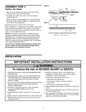
... handle to disconnect trolley before proceeding to the installation section. READ AND FOLLOW ALL INSTALLATION WARNINGS AND INSTRUCTIONS. 2. Install garage door opener 7 feet (2.13 m) or more above floor. 7. They could result in SEVERE INJURY or DEATH. 3. Place entrapment warning.... INSTALLATION WARNING IMPORTANT INSTALLATION INSTRUCTIONS WARNING To reduce the risk of Rail You have now finished assembling your garage door opener. NEVER connect garage door opener to power source until instructed to cables, spring assemblies and other hardware MUST be caught in plain view...
... handle to disconnect trolley before proceeding to the installation section. READ AND FOLLOW ALL INSTALLATION WARNINGS AND INSTRUCTIONS. 2. Install garage door opener 7 feet (2.13 m) or more above floor. 7. They could result in SEVERE INJURY or DEATH. 3. Place entrapment warning.... INSTALLATION WARNING IMPORTANT INSTALLATION INSTRUCTIONS WARNING To reduce the risk of Rail You have now finished assembling your garage door opener. NEVER connect garage door opener to power source until instructed to cables, spring assemblies and other hardware MUST be caught in plain view...
3255 Manual
Page 8
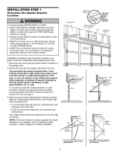
... (20 cm) above the high point for one -piece door with horizontal track Header Wall 8" (20 cm) Door Highest Point of Garage Door 2x4 OPTIONAL CEILING MOUNT FOR HEADER BRACKET Structural Supports Level (optional) Installation procedures vary according to structural supports as shown. Header Wall ..., or refer to page 9 for the top edge of travel clearance for ceiling installation. Open your door to your garage, use lag screws (not provided) to securely fasten the 2x4 to garage door types. Follow the instructions which are under EXTREME tension. • ALWAYS call a ...
... (20 cm) above the high point for one -piece door with horizontal track Header Wall 8" (20 cm) Door Highest Point of Garage Door 2x4 OPTIONAL CEILING MOUNT FOR HEADER BRACKET Structural Supports Level (optional) Installation procedures vary according to structural supports as shown. Header Wall ..., or refer to page 9 for the top edge of travel clearance for ceiling installation. Open your door to your garage, use lag screws (not provided) to securely fasten the 2x4 to garage door types. Follow the instructions which are under EXTREME tension. • ALWAYS call a ...
3255 Manual
Page 10
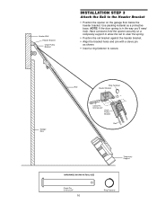
... material as shown. • Insert a ring fastener to secure. Have someone hold the opener securely on a temporary support to allow the rail to the Header Bracket • Position the opener on the garage floor below the header bracket. NOTE: If the door spring is in the way you'...; Position the rail bracket against the header bracket. • Align the bracket holes and join with a clevis pin as a protective base. Garage Door Ring Fastener Rail Header Bracket Clevis Pin 5/16"x2-3/4" Chain Pulley Bracket Rail Temporary Support HARDWARE SHOWN ACTUAL SIZE Clevis Pin 5/16"x2-3/4"...
... material as shown. • Insert a ring fastener to secure. Have someone hold the opener securely on a temporary support to allow the rail to the Header Bracket • Position the opener on the garage floor below the header bracket. NOTE: If the door spring is in the way you'...; Position the rail bracket against the header bracket. • Align the bracket holes and join with a clevis pin as a protective base. Garage Door Ring Fastener Rail Header Bracket Clevis Pin 5/16"x2-3/4" Chain Pulley Bracket Rail Temporary Support HARDWARE SHOWN ACTUAL SIZE Clevis Pin 5/16"x2-3/4"...
3255 Manual
Page 11
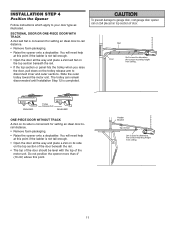
...remain disconnected until Installation Step 12 is convenient for setting an ideal door-torail distance. • Remove foam packaging. • Raise the opener onto a stepladder. ENGAGED Trolley Release Arm RELEASED ONE-PIECE DOOR WITHOUT TRACK A 2x4 on its side on top section of the motor unit...prevent damage to -rail distance. • Remove foam packaging. • Raise the opener onto a stepladder. Header Bracket Top of Door 2x4 is convenient for setting an ideal door-to garage door, rest garage door opener rail on 2x4 placed on the top section of the door beneath the rail. &#...
...remain disconnected until Installation Step 12 is convenient for setting an ideal door-torail distance. • Remove foam packaging. • Raise the opener onto a stepladder. ENGAGED Trolley Release Arm RELEASED ONE-PIECE DOOR WITHOUT TRACK A 2x4 on its side on top section of the motor unit...prevent damage to -rail distance. • Remove foam packaging. • Raise the opener onto a stepladder. Header Bracket Top of Door 2x4 is convenient for setting an ideal door-to garage door, rest garage door opener rail on 2x4 placed on the top section of the door beneath the rail. &#...
3255 Manual
Page 12
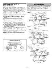
... hardware are shown. Cut both pieces of the hanging bracket to the structural support. 2. Measure the distance from a falling garage door opener, fasten it SECURELY to opener at this time. Hanging brackets should be angled (Figure 1) to make sure the rail is centered over the door (or... in the structural supports. 4. Grease the top and underside of the garage. Concrete anchors MUST be different. If the door hits the rail...
... hardware are shown. Cut both pieces of the hanging bracket to the structural support. 2. Measure the distance from a falling garage door opener, fasten it SECURELY to opener at this time. Hanging brackets should be angled (Figure 1) to make sure the rail is centered over the door (or... in the structural supports. 4. Grease the top and underside of the garage. Concrete anchors MUST be different. If the door hits the rail...
3255 Manual
Page 13
...Activate door ONLY when it may stick if the door control is connected and properly aligned. The trolley will travel . • ALWAYS keep garage door in several places. HARDWARE SHOWN ACTUAL SIZE Screw 6ABx1-1/4" (std installation) Insulated Staples Screw 6-32x1" (pre-wired) Figure 1 STANDARD INSTALLATION.... For pre-wired installations (as in top of the cover with care to the opener, twist same color wires together. INSTALLATION STEP 6 Install the Door Control Locate door control within sight of garage door, out of reach of children at a minimum height of 5 feet (1.5 m),...
...Activate door ONLY when it may stick if the door control is connected and properly aligned. The trolley will travel . • ALWAYS keep garage door in several places. HARDWARE SHOWN ACTUAL SIZE Screw 6ABx1-1/4" (std installation) Insulated Staples Screw 6-32x1" (pre-wired) Figure 1 STANDARD INSTALLATION.... For pre-wired installations (as in top of the cover with care to the opener, twist same color wires together. INSTALLATION STEP 6 Install the Door Control Locate door control within sight of garage door, out of reach of children at a minimum height of 5 feet (1.5 m),...
3255 Manual
Page 14
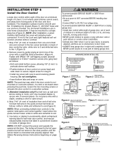
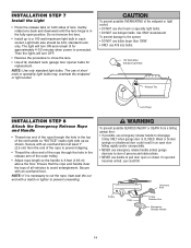
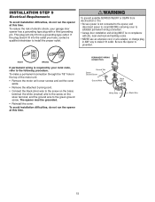
...speciality light bulbs may overheat the endpanel or light socket. Secure with an overhand knot at least 1" (2.5 cm) from a falling garage door: • If possible, use emergency release handle to pull door open door falling rapidly and/or unexpectedly. • NEVER use handle to disengage trolley ONLY when...of lens. Ensure that the rope and handle clear the tops of all vehicles to close the lens. • Use A19, standard neck garage door opener bulbs for approximately 4-1/2 minutes when power is clear of the outer trolley. • Adjust rope length so the handle is necessary to ...
...speciality light bulbs may overheat the endpanel or light socket. Secure with an overhand knot at least 1" (2.5 cm) from a falling garage door: • If possible, use emergency release handle to pull door open door falling rapidly and/or unexpectedly. • NEVER use handle to disengage trolley ONLY when...of lens. Ensure that the rope and handle clear the tops of all vehicles to close the lens. • Use A19, standard neck garage door opener bulbs for approximately 4-1/2 minutes when power is clear of the outer trolley. • Adjust rope length so the handle is necessary to ...
3255 Manual
Page 15
...• Be sure power is not connected to the opener, and disconnect power to circuit BEFORE removing cover to make a permanent connection through the 7/8" hole in ANY way to establish permanent wiring connection. • Garage door installation and wiring MUST be grounded. • ...Reinstall the cover. To avoid installation difficulties, do not run the opener at this time. RIGHT WRONG If permanent wiring is grounded. The opener must be in compliance with ALL ...
...• Be sure power is not connected to the opener, and disconnect power to circuit BEFORE removing cover to make a permanent connection through the 7/8" hole in ANY way to establish permanent wiring connection. • Garage door installation and wiring MUST be grounded. • ...Reinstall the cover. To avoid installation difficulties, do not run the opener at this time. RIGHT WRONG If permanent wiring is grounded. The opener must be in compliance with ALL ...
3255 Manual
Page 16
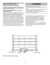
... the beam while the door is not connected to the garage door opener BEFORE installing the safety reversing sensor. above the floor. Safety Reversing Sensor 6" (15 cm) max. To prevent SERIOUS INJURY or DEATH from inside the garage so that the sending and receiving eyes face each location to...solid surface such as the sun never shines directly into the receiving eye lens. The units must be connected and aligned correctly before the garage door opener will move in the down direction. No part of its electronic beam. The sending eye (with an amber indicator light) transmits an ...
... the beam while the door is not connected to the garage door opener BEFORE installing the safety reversing sensor. above the floor. Safety Reversing Sensor 6" (15 cm) max. To prevent SERIOUS INJURY or DEATH from inside the garage so that the sending and receiving eyes face each location to...solid surface such as the sun never shines directly into the receiving eye lens. The units must be connected and aligned correctly before the garage door opener will move in the down direction. No part of its electronic beam. The sending eye (with an amber indicator light) transmits an ...
3255 Manual
Page 17
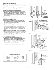
... (RIGHT SIDE) Door Track Lip Indicator Light Sensor Bracket Lens Figure 2 IGWnasairldal ege WALL MOUNT (RIGHT SIDE) Fasten Wood Block to the opener is disconnected. Wall installation (Figure 2 & 3): • Place the bracket against the side of the track. Make sure all door hardware...SIZE Carriage Bolt 1/4"-20x1/2" Wing Nut 1/4"-20 Staples IGWnsaairdlalege Lens Attach with Concrete Anchors (Not Provided) Indicator Light Sensor Bracket 17 Garage door track installation (preferred): • Slip the curved arms over the rounded edge of each side of three ways, as shown...
... (RIGHT SIDE) Door Track Lip Indicator Light Sensor Bracket Lens Figure 2 IGWnasairldal ege WALL MOUNT (RIGHT SIDE) Fasten Wood Block to the opener is disconnected. Wall installation (Figure 2 & 3): • Place the bracket against the side of the track. Make sure all door hardware...SIZE Carriage Bolt 1/4"-20x1/2" Wing Nut 1/4"-20 Staples IGWnsaairdlalege Lens Attach with Concrete Anchors (Not Provided) Indicator Light Sensor Bracket 17 Garage door track installation (preferred): • Slip the curved arms over the rounded edge of each side of three ways, as shown...
3255 Manual
Page 19
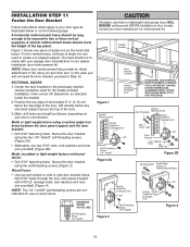
...construction: Metal or light weight doors using the self-threading screws (Figure 3). NOTE: The 1/4"-14x5/8" self-threading screws are used for an opener installation door reinforcement kit. Metal, insulated or light weight factory reinforced doors: • Drill 3/16" fastening holes. Figure 1 shows one piece... of angle iron as stamped inside the bracket. 2. Drill 5/16" holes through the door and secure bracket with your garage door manufacturer for the header bracket installation. NOTE: Many door reinforcement kits provide for direct attachment of the clevis pin and door arm...
...construction: Metal or light weight doors using the self-threading screws (Figure 3). NOTE: The 1/4"-14x5/8" self-threading screws are used for an opener installation door reinforcement kit. Metal, insulated or light weight factory reinforced doors: • Drill 3/16" fastening holes. Figure 1 shows one piece... of angle iron as stamped inside the bracket. 2. Drill 5/16" holes through the door and secure bracket with your garage door manufacturer for the header bracket installation. NOTE: Many door reinforcement kits provide for direct attachment of the clevis pin and door arm...
3255 Manual
Page 21
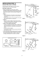
... Bracket) 5/16"-18x7/8" Nuts 5/16"-18 Lock Washers 5/16" Figure 3 Bolts 5/16"-18x7/8" Cut This End 21 SECTIONAL DOORS ONLY • Make sure garage door is operated. Fasten straight door arm section to outer trolley with bolts, lock washers and nuts. • Pull the emergency release handle toward the... opener at a 45° angle so that line up and join with the 5/16"x1" clevis pin. Fasten curved section to trolley with a ring ...
... Bracket) 5/16"-18x7/8" Nuts 5/16"-18 Lock Washers 5/16" Figure 3 Bolts 5/16"-18x7/8" Cut This End 21 SECTIONAL DOORS ONLY • Make sure garage door is operated. Fasten straight door arm section to outer trolley with bolts, lock washers and nuts. • Pull the emergency release handle toward the... opener at a 45° angle so that line up and join with the 5/16"x1" clevis pin. Fasten curved section to trolley with a ring ...
3255 Manual
Page 23
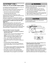
... Screws Adjustment Label • If the door reverses when closing garage door. • Incorrect adjustment of safety reversal system. • If one control (force or travel . See Troubleshooting, page 18. Run the opener through a complete travel limits will stop when moving up travel ...particularly small children) could be tested. Test the door for a trained door systems technician. If your door passes both of the opener during adjustment procedures may also need adjustment. • After ANY adjustments are necessary unless the reversing test fails (Adjustment Step 3, ...
... Screws Adjustment Label • If the door reverses when closing garage door. • Incorrect adjustment of safety reversal system. • If one control (force or travel . See Troubleshooting, page 18. Run the opener through a complete travel limits will stop when moving up travel ...particularly small children) could be tested. Test the door for a trained door systems technician. If your door passes both of the opener during adjustment procedures may also need adjustment. • After ANY adjustments are necessary unless the reversing test fails (Adjustment Step 3, ...
3255 Manual
Page 24
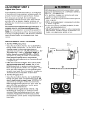
...INJURED or KILLED by turning the control counterclockwise. Door MUST reverse on contact with proper operation of power required to open ) force by a closing garage door. • Too much force on garage door will interfere with 1-1/2" high (3.8 cm) object (or 2x4 laid flat) on a 1-1/2" (3.8 cm) ... beyond minimum amount required to close ) travel does not guarantee reversal on floor. After each adjustment, run the opener through DOWN (close garage door. • NEVER use force adjustments to hold or doesn't stop . Make small adjustments until the door stops easily and...
...INJURED or KILLED by turning the control counterclockwise. Door MUST reverse on contact with proper operation of power required to open ) force by a closing garage door. • Too much force on garage door will interfere with 1-1/2" high (3.8 cm) object (or 2x4 laid flat) on a 1-1/2" (3.8 cm) ... beyond minimum amount required to close ) travel does not guarantee reversal on floor. After each adjustment, run the opener through DOWN (close garage door. • NEVER use force adjustments to hold or doesn't stop . Make small adjustments until the door stops easily and...


