
Service Manual
Page 24
... Information contains a general description of printer problems. 4. Preventive Maintenance contains the lubrication specifications and recommendations to repair it. Special tools and test equipment are listed in this chapter, as well as general environmental and safety...and checks used to locate or repeat symptoms of the printer and the maintenance approach used to prevent problems. 7. xxiv Service Manual Repair Information provides instructions for individual FRUs. Diagnostic Information contains an error indicator table, symptom tables, and service checks used to isolate ...
... Information contains a general description of printer problems. 4. Preventive Maintenance contains the lubrication specifications and recommendations to repair it. Special tools and test equipment are listed in this chapter, as well as general environmental and safety...and checks used to locate or repeat symptoms of the printer and the maintenance approach used to prevent problems. 7. xxiv Service Manual Repair Information provides instructions for individual FRUs. Diagnostic Information contains an error indicator table, symptom tables, and service checks used to isolate ...
Service Manual
Page 27
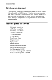
... service checks, and diagnostic aids to verify the repair. After you to the correct field replaceable unit (FRU) or part. 4069-5XX/7XX Maintenance Approach The diagnostic information in this manual leads you complete the repair, perform tests as needed to determine the printer problem... and repair the failure. Tools Required for Service Flat-blade screwdriver #1 Phillips screwdriver #2 Phillips screwdriver ...
... service checks, and diagnostic aids to verify the repair. After you to the correct field replaceable unit (FRU) or part. 4069-5XX/7XX Maintenance Approach The diagnostic information in this manual leads you complete the repair, perform tests as needed to determine the printer problem... and repair the failure. Tools Required for Service Flat-blade screwdriver #1 Phillips screwdriver #2 Phillips screwdriver ...

Service Manual
Page 88
... NOT rotating. Check all the gears for correct installation and for signs of damage. If incorrect, replace the master kick gear. 2-60 Service Manual If incorrect, replace the envelope system board, if correct, measure the voltage at J4-6. If correct, replace the D.C. Check to make sure ...the hopper. If not, then the tenons on J4-1. 4069-5XX/7XX 990 Service Error, envelopes fail to make sure it moves freely. Repair or replace parts as necessary. If incorrect, replace the envelope feeder system board. If incorrect, disconnect J4 and measure the voltage again. motor ...
... NOT rotating. Check all the gears for correct installation and for signs of damage. If incorrect, replace the master kick gear. 2-60 Service Manual If incorrect, replace the envelope system board, if correct, measure the voltage at J4-6. If correct, replace the D.C. Check to make sure ...the hopper. If not, then the tenons on J4-1. 4069-5XX/7XX 990 Service Error, envelopes fail to make sure it moves freely. Repair or replace parts as necessary. If incorrect, replace the envelope feeder system board. If incorrect, disconnect J4 and measure the voltage again. motor ...

Service Manual
Page 98
... x option pass thru sensor assembly. Check the drive roll assembly and skewed backup roller for signs of paper from the diagnostics menu. Repair or replace parts as necessary. 2-70 Service Manual Example: 241 is correctly connected to the drive shaft bearings. Check these parts for proper operation. If the test fails, check...
... x option pass thru sensor assembly. Check the drive roll assembly and skewed backup roller for signs of paper from the diagnostics menu. Repair or replace parts as necessary. 2-70 Service Manual Example: 241 is correctly connected to the drive shaft bearings. Check these parts for proper operation. If the test fails, check...

Service Manual
Page 102
... voltages at J11-2 and J11-4. If incorrect, replace the AC cable to the LVPS. Repair the high capacity option autoconnect as necessary. Check the option or base printer autoconnect for signs of the LVPS. 2-74 Service Manual If the voltage is not pushed down into the frame assembly or damaged. Be sure...
... voltages at J11-2 and J11-4. If incorrect, replace the AC cable to the LVPS. Repair the high capacity option autoconnect as necessary. Check the option or base printer autoconnect for signs of the LVPS. 2-74 Service Manual If the voltage is not pushed down into the frame assembly or damaged. Be sure...

Service Manual
Page 104
... thru sensor and flag for proper operation of the paper aligning assembly. Remove any jammed sheets of paper from the diagnostics menu. Repair or replace parts as necessary. 2-76 Service Manual Also check the sensor cable to make sure it is a Paper Jam Tray 2) FRU 1 Pass Thru Sensor and Flag Assembly 2 Power...
... thru sensor and flag for proper operation of the paper aligning assembly. Remove any jammed sheets of paper from the diagnostics menu. Repair or replace parts as necessary. 2-76 Service Manual Also check the sensor cable to make sure it is a Paper Jam Tray 2) FRU 1 Pass Thru Sensor and Flag Assembly 2 Power...
Service Manual
Page 122
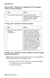
... Flag Assembly Control Board Action Check the sensor flag for the failing sensor. Disconnect the pass thru sensor cable from the sensor cable, If incorrect, repair as necessary. 271 Paper Jam - If this does not fix the problem, replace the control board. 271 Paper Jam - 4069-5XX/7XX Remove Paper - Output... on the control board. If correct, check the voltage at J3-3. Check Bin X, POST complete, first sheet of sensor assembly) P = Pass Thru Sensor 2-94 Service Manual
... Flag Assembly Control Board Action Check the sensor flag for the failing sensor. Disconnect the pass thru sensor cable from the sensor cable, If incorrect, repair as necessary. 271 Paper Jam - If this does not fix the problem, replace the control board. 271 Paper Jam - 4069-5XX/7XX Remove Paper - Output... on the control board. If correct, check the voltage at J3-3. Check Bin X, POST complete, first sheet of sensor assembly) P = Pass Thru Sensor 2-94 Service Manual
Service Manual
Page 126
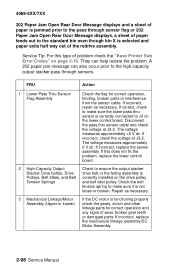
...failing assembly is Pulleys, Belt Idlers, and Belt correctly installed on the drive pulley Tension Springs and belt idler pulley. If incorrect, repair as necessary. 3 Mechanical Linkage/Motor Assembly (Upper or Lower) If the DC motor is functioning properly check the gears, clutch ...The voltage measures approximately +5 V dc. If incorrect, replace the mechanical linkage assembly/DC Motor Assembly. 2-98 Service Manual If incorrect, replace the sensor assembly. Repair as necessary. If correct, check to make sure the lower pass thru sensor is correctly connected to make sure it ...
...failing assembly is Pulleys, Belt Idlers, and Belt correctly installed on the drive pulley Tension Springs and belt idler pulley. If incorrect, repair as necessary. 3 Mechanical Linkage/Motor Assembly (Upper or Lower) If the DC motor is functioning properly check the gears, clutch ...The voltage measures approximately +5 V dc. If incorrect, replace the mechanical linkage assembly/DC Motor Assembly. 2-98 Service Manual If incorrect, replace the sensor assembly. Repair as necessary. If correct, check to make sure the lower pass thru sensor is correctly connected to make sure it ...

Service Manual
Page 146
... charge links and arms for any signs of line J25-8 in the front cable harness. If correct, replace the system board. 2-118 Service Manual 4069-5XX/7XX FRU 2 Charge Roll Assembly Charge Roll Link Arm 3 HVPS Action Check the charge roll for proper operation, binds or incorrectly ...mounted counterbalance springs. Repair or replace as necessary. If there is continuity, replace the HVPS. If this does not correct the problem, replace the system board. The ...
... charge links and arms for any signs of line J25-8 in the front cable harness. If correct, replace the system board. 2-118 Service Manual 4069-5XX/7XX FRU 2 Charge Roll Assembly Charge Roll Link Arm 3 HVPS Action Check the charge roll for proper operation, binds or incorrectly ...mounted counterbalance springs. Repair or replace as necessary. If there is continuity, replace the HVPS. If this does not correct the problem, replace the system board. The ...

Service Manual
Page 148
... 2 Transfer Roll Transfer Plate Assembly Action Toner is generally caused by loose toner in the machine in the following order: HVPS system board 2-120 Service Manual Repair as necessary.
... 2 Transfer Roll Transfer Plate Assembly Action Toner is generally caused by loose toner in the machine in the following order: HVPS system board 2-120 Service Manual Repair as necessary.

