
Setup Guide
Page 2
... laser, exercise CAUTION: Use of controls or adjustments or performance of Lab Operations Lexmark International, Inc. 740 West New Circle Road NW Lexington, KY 40550 (859) 232-3000 Refer to the Lexmark T620/T622 Publications CD for selecting print media to avoid the possibility of the FCC...distribute any of the information you supply in conjunction with this symbol , it MUST be connected to an electrical outlet that is properly grounded. • The power cord must be used under license. therefore, this statement may not apply to Lexmark International Ltd., Marketing and Services ...
... laser, exercise CAUTION: Use of controls or adjustments or performance of Lab Operations Lexmark International, Inc. 740 West New Circle Road NW Lexington, KY 40550 (859) 232-3000 Refer to the Lexmark T620/T622 Publications CD for selecting print media to avoid the possibility of the FCC...distribute any of the information you supply in conjunction with this symbol , it MUST be connected to an electrical outlet that is properly grounded. • The power cord must be used under license. therefore, this statement may not apply to Lexmark International Ltd., Marketing and Services ...
Technical Reference
Page 336
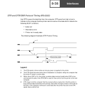
... remain in ready state The following diagram illustrates DTR Protocol Timing. 1 2 3 Receive Data Valid 4 Legend: 1 The RTS signal is driven active as long as power is supplied to the printer. 2 The DTR signal becomes active when initialization is complete, telling the computer that the printer is ready to receive data. 3 When Honor...
... remain in ready state The following diagram illustrates DTR Protocol Timing. 1 2 3 Receive Data Valid 4 Legend: 1 The RTS signal is driven active as long as power is supplied to the printer. 2 The DTR signal becomes active when initialization is complete, telling the computer that the printer is ready to receive data. 3 When Honor...
Technical Reference
Page 337
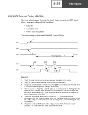
...Protocol Timing. 1 RTS DTR 2 DSR 3 Receive Data Valid XMT RXD XON 4 XOFF XON 5 6 Legend: 1 The RTS signal is driven active as long as power is supplied to the printer. 2 The DTR signal becomes active at this initial XON before the computer or terminal. 5 The printer sends an XOFF signal (DC3 control...considers data received invalid when DSR is low and discards the data. (This is conditional depending on the setting of Honor DSR.) 4 After you power on before sending data to the printer, because the printer can be lost. 6 The printer sends an XON signal to the computer when the ...
...Protocol Timing. 1 RTS DTR 2 DSR 3 Receive Data Valid XMT RXD XON 4 XOFF XON 5 6 Legend: 1 The RTS signal is driven active as long as power is supplied to the printer. 2 The DTR signal becomes active at this initial XON before the computer or terminal. 5 The printer sends an XOFF signal (DC3 control...considers data received invalid when DSR is low and discards the data. (This is conditional depending on the setting of Honor DSR.) 4 After you power on before sending data to the printer, because the printer can be lost. 6 The printer sends an XON signal to the computer when the ...

Service Manual
Page 6
...35 Fuser Lamp 4-35 Fuser Lower Exit Guide Assembly 4-36 High Voltage Power Supply 4-37 Integrated Tray Compensator Assembly 4-37 Integrated Tray Compensator Pick Roll Assembly . . . . . .4-38 Interconnect Board Assembly 4-40 Low Voltage Power Supply 4-42 Main Drive Assembly 4-43 Main Drive Motor 4-45 Multipurpose Tray/... Upper Front Cover Hinge Assembly 4-61 Upper Front Cover Interlock Switch Assembly 4-62 Connector Locations 5-1 Low Voltage Power Supply 5-1 High Voltage Power Supply 5-3 Interconnect Board 5-4 Envelope Option Board 5-7 Duplex Option Board 5-9 vi Service Manual
...35 Fuser Lamp 4-35 Fuser Lower Exit Guide Assembly 4-36 High Voltage Power Supply 4-37 Integrated Tray Compensator Assembly 4-37 Integrated Tray Compensator Pick Roll Assembly . . . . . .4-38 Interconnect Board Assembly 4-40 Low Voltage Power Supply 4-42 Main Drive Assembly 4-43 Main Drive Motor 4-45 Multipurpose Tray/... Upper Front Cover Hinge Assembly 4-61 Upper Front Cover Interlock Switch Assembly 4-62 Connector Locations 5-1 Low Voltage Power Supply 5-1 High Voltage Power Supply 5-3 Interconnect Board 5-4 Envelope Option Board 5-7 Duplex Option Board 5-9 vi Service Manual

Service Manual
Page 28
... Read-Only Memory Electrostatic Discharge Field Replaceable Unit Gigabyte High Voltage Power Supply Light Amplification by Stimulated Emission of Radiation Liquid Crystal Display Light-Emitting Diode Low Voltage Power Supply Masked Read Only Memory Nonvolatile Random Access Memory Original Equipment Manufacturer Photoconductor Power-On Reset Power-On Self Test Raster Imaging Processor Read Only Memory Synchronous...
... Read-Only Memory Electrostatic Discharge Field Replaceable Unit Gigabyte High Voltage Power Supply Light Amplification by Stimulated Emission of Radiation Liquid Crystal Display Light-Emitting Diode Low Voltage Power Supply Masked Read Only Memory Nonvolatile Random Access Memory Original Equipment Manufacturer Photoconductor Power-On Reset Power-On Self Test Raster Imaging Processor Read Only Memory Synchronous...

Service Manual
Page 33
4069-5XX/7XX Error Code Action 940 Service LV Power Supply The low voltage power supply zero crossover test failed. • Check the LVPS for correct installation. Replace the system board. 949 Delay Line Calibration Failure Indicates a delay line calibration failure. ... CRC failure, the location (loc) will be a failing block or (Bn). * = For a NAND CRC failure, the location (loc) will be caused by a noisy AC input power source. • Check to make sure the correct LVPS has been installed. • If all the above are system board failures. *956 = Processor Failure *957...
4069-5XX/7XX Error Code Action 940 Service LV Power Supply The low voltage power supply zero crossover test failed. • Check the LVPS for correct installation. Replace the system board. 949 Delay Line Calibration Failure Indicates a delay line calibration failure. ... CRC failure, the location (loc) will be a failing block or (Bn). * = For a NAND CRC failure, the location (loc) will be caused by a noisy AC input power source. • Check to make sure the correct LVPS has been installed. • If all the above are system board failures. *956 = Processor Failure *957...

Service Manual
Page 80
... board If correct, turn the printer off and disconnect all necessary safety precautions before applying AC power. Service Tip: A short or low resistance load that is attached to the system board can pull the +5V dc supply down to the system board. 2-52 Service Manual If incorrect replace the FRU in the...
... board If correct, turn the printer off and disconnect all necessary safety precautions before applying AC power. Service Tip: A short or low resistance load that is attached to the system board can pull the +5V dc supply down to the system board. 2-52 Service Manual If incorrect replace the FRU in the...

Service Manual
Page 247
4069-5XX/7XX High Voltage Power Supply 1. The cable and connector can be easily damaged. 6. Integrated Tray Compensator Assembly 1. Repair Information 4-37 Remove the right side cover. 4. Warning: Use care when disconnecting ...
4069-5XX/7XX High Voltage Power Supply 1. The cable and connector can be easily damaged. 6. Integrated Tray Compensator Assembly 1. Repair Information 4-37 Remove the right side cover. 4. Warning: Use care when disconnecting ...

Service Manual
Page 252
4069-5XX/7XX Low Voltage Power Supply 1. Remove the right cover. 2. Pull the LVPS assembly from the right side of the bottom pan. 3. Remove the LVPS mounting screws (A) from the LVPS. 5. Press the release latch on the fuser lamp cable connector and disconnect from the rear of the printer. Initial resistance is felt as the automate plug disconnects. 4. Remove the LVPS. 4-42 Service Manual
4069-5XX/7XX Low Voltage Power Supply 1. Remove the right cover. 2. Pull the LVPS assembly from the right side of the bottom pan. 3. Remove the LVPS mounting screws (A) from the LVPS. 5. Press the release latch on the fuser lamp cable connector and disconnect from the rear of the printer. Initial resistance is felt as the automate plug disconnects. 4. Remove the LVPS. 4-42 Service Manual

Service Manual
Page 273
4069-5XX/7XX 5. Connector Locations Low Voltage Power Supply Connector CN3 Interconnect Board Pin No. 1 2 3 4 5 6 7 8 9 10 11 12 13 14 15 16 17 18 Signal +5 V dc +5 V dc Ground Ground Ground Ground +24 V dc +24 V dc Heat on +5 V dc +5 V dc Ground Ground Ground Ground +24 V dc ZC Out* +42 V dc Connector Locations 5-1
4069-5XX/7XX 5. Connector Locations Low Voltage Power Supply Connector CN3 Interconnect Board Pin No. 1 2 3 4 5 6 7 8 9 10 11 12 13 14 15 16 17 18 Signal +5 V dc +5 V dc Ground Ground Ground Ground +24 V dc +24 V dc Heat on +5 V dc +5 V dc Ground Ground Ground Ground +24 V dc ZC Out* +42 V dc Connector Locations 5-1

Service Manual
Page 275
4069-5XX/7XX High Voltage Power Supply Connector CN1 System Board Pin No. 1 2 3 4 5 6 7 8 Signal Developer PWM +24 V dc Return Charge PWM +24 V dc IN TX PWM TX Enable TX CUR PWM SVRO OUT Connector Locations 5-3
4069-5XX/7XX High Voltage Power Supply Connector CN1 System Board Pin No. 1 2 3 4 5 6 7 8 Signal Developer PWM +24 V dc Return Charge PWM +24 V dc IN TX PWM TX Enable TX CUR PWM SVRO OUT Connector Locations 5-3

Service Manual
Page 309
If any non-Lexmark attachments Lubrication Specifications Lubricate only when parts are replaced or as needed, not on a scheduled basis. Use of this inspection guide is to lubricate appropriate areas of the top cover and the power supply cover • Possible safety exposure from any...Check the following items: • Damaged, missing, or altered parts, especially in the area of the On/Off switch and the power supply • Damaged, missing, or altered covers, especially in identifying unsafe conditions. Following these recommendations can cause premature failure. Some unauthorized ...
If any non-Lexmark attachments Lubrication Specifications Lubricate only when parts are replaced or as needed, not on a scheduled basis. Use of this inspection guide is to lubricate appropriate areas of the top cover and the power supply cover • Possible safety exposure from any...Check the following items: • Damaged, missing, or altered parts, especially in the area of the On/Off switch and the power supply • Damaged, missing, or altered covers, especially in identifying unsafe conditions. Following these recommendations can cause premature failure. Some unauthorized ...

Service Manual
Page 347
... V ac 520/52n 1 LVPS, 110 V ac 722/72n 1 LVPS, 220 V ac 520/52n 1 LVPS, 220 V ac 722/72n 1 Screw, HVPS Mounting PP 99A0263 1 High Voltage Power Supply 1 Interconnect Board Assembly o 2 Slot with shield 2 Screw, Int Board Mounting PP 99A0263 3 Screw, System Bd Mounting Front PP 99A0263 2 Screw, Parallel Connector Mounting 1 Card Assembly...
... V ac 520/52n 1 LVPS, 110 V ac 722/72n 1 LVPS, 220 V ac 520/52n 1 LVPS, 220 V ac 722/72n 1 Screw, HVPS Mounting PP 99A0263 1 High Voltage Power Supply 1 Interconnect Board Assembly o 2 Slot with shield 2 Screw, Int Board Mounting PP 99A0263 3 Screw, System Bd Mounting Front PP 99A0263 2 Screw, Parallel Connector Mounting 1 Card Assembly...

Service Manual
Page 389
... Mounting PP 99A0675 1 Pulley, Idler 1 Belt, Drive 1 Cable, AC Internal Wiring 2 Nut, 2-56 Lower Limit Switch Mounting PP 99A0676 1 Switch, Lower Limit Microswitch 2 Nut, Power Supply Ground PP 99A0676 4 Washer, Motor Plate Mounting PP 99A0677 1 Cord, AC External Jumper 2 Nut, Power Supply Cover PP 99A0676 1 Cover, Power Supply 2 Screw, Power Supply Board Mounting PP 99A0675 Parts Catalog 7-79
... Mounting PP 99A0675 1 Pulley, Idler 1 Belt, Drive 1 Cable, AC Internal Wiring 2 Nut, 2-56 Lower Limit Switch Mounting PP 99A0676 1 Switch, Lower Limit Microswitch 2 Nut, Power Supply Ground PP 99A0676 4 Washer, Motor Plate Mounting PP 99A0677 1 Cord, AC External Jumper 2 Nut, Power Supply Cover PP 99A0676 1 Cover, Power Supply 2 Screw, Power Supply Board Mounting PP 99A0675 Parts Catalog 7-79

Service Manual
Page 391
... 20-55 99A0654 99A0651 20-56 99A0659 20-57 99A0695 20-58 20-59 NS NS 99A0684 NS NS Units Description 2 Washer, Power Supply Board PP 99A0677 1 Power Supply Board 1 Cable, Low Voltage Power Supply 1 Bushing 2 Nut, 2-56 Paper Low Switch Mounting PP 99A0676 1 Switch, Paper Low 1 Sensor Assembly, Paper Out/Upper Limit 3 Screw, Printer Support...
... 20-55 99A0654 99A0651 20-56 99A0659 20-57 99A0695 20-58 20-59 NS NS 99A0684 NS NS Units Description 2 Washer, Power Supply Board PP 99A0677 1 Power Supply Board 1 Cable, Low Voltage Power Supply 1 Bushing 2 Nut, 2-56 Paper Low Switch Mounting PP 99A0676 1 Switch, Paper Low 1 Sensor Assembly, Paper Out/Upper Limit 3 Screw, Printer Support...

Service Manual
Page 425
... Alignment Assembly 4-5 Printhead Assembly 4-4 Autoconnect 5-11 B Base Sensor Test 3-26 Button Test 3-14 C Connector Locations Autoconnect 5-11 Duplex Option Board 5-9 Envelope Option Board 5-7 High Voltage Power Supply 5-3 High-Capacity Output Stacker Board 5-14 Interconnect Board 5-4 LVPS 5-1 Output Expander Control Board 5-12 D Diagnostic Aids Device Tests 3-6 Disk Test/Clean 3-6 Flash Test 3-7 Quick Disk...
... Alignment Assembly 4-5 Printhead Assembly 4-4 Autoconnect 5-11 B Base Sensor Test 3-26 Button Test 3-14 C Connector Locations Autoconnect 5-11 Duplex Option Board 5-9 Envelope Option Board 5-7 High Voltage Power Supply 5-3 High-Capacity Output Stacker Board 5-14 Interconnect Board 5-4 LVPS 5-1 Output Expander Control Board 5-12 D Diagnostic Aids Device Tests 3-6 Disk Test/Clean 3-6 Flash Test 3-7 Quick Disk...


