
Troubleshooting Guide
Page 1
... seconds, and turn the printer off by any switch or breaker. • The printer is not plugged into any surge protectors, uninterrupted power supplies, or extension cords. • Other electrical equipment plugged into the printer and a properly grounded electrical outlet. • The electrical outlet ... is securely attached to the printer and the host computer, print server, option, or other countries/ regions, visit the Lexmark Web site at www.lexmark.com Note: When calling for network printing. Only specific USB flash memory devices are experiencing, the message on . •...
... seconds, and turn the printer off by any switch or breaker. • The printer is not plugged into any surge protectors, uninterrupted power supplies, or extension cords. • Other electrical equipment plugged into the printer and a properly grounded electrical outlet. • The electrical outlet ... is securely attached to the printer and the host computer, print server, option, or other countries/ regions, visit the Lexmark Web site at www.lexmark.com Note: When calling for network printing. Only specific USB flash memory devices are experiencing, the message on . •...

User's Guide
Page 87
...8226; The electrical outlet is not turned off by any switch or breaker. • The printer is not plugged into any surge protectors, uninterrupted power supplies, or extension cords. • Other electrical equipment plugged into the outlet is working. • The printer is turned on. • The printer... dialog box appears. 3 Check the Print as Image option. 4 Click OK. See the label on the Lexmark Web site at www.lexmark.com Note: When calling for service, call 1-800-Lexmark (1-800-539-6275). Cause The documents contain unavailable fonts. Note: For Acrobat 7.x or later, click the ...
...8226; The electrical outlet is not turned off by any switch or breaker. • The printer is not plugged into any surge protectors, uninterrupted power supplies, or extension cords. • Other electrical equipment plugged into the outlet is working. • The printer is turned on. • The printer... dialog box appears. 3 Check the Print as Image option. 4 Click OK. See the label on the Lexmark Web site at www.lexmark.com Note: When calling for service, call 1-800-Lexmark (1-800-539-6275). Cause The documents contain unavailable fonts. Note: For Acrobat 7.x or later, click the ...
Service Manual
Page 8
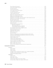
..., magenta and yellow 5-4 Cartridge contact assembly pin locations (black 5-5 System board cabling reference 5-6 Connectors 5-7 System board 5-7 Autoconnect-top 5-18 Autoconnect-bottom 5-19 Transfer high voltage power supply (HVPS 5-20 Developer high voltage power supply (HVPS) board 5-22 viii Service Manual
..., magenta and yellow 5-4 Cartridge contact assembly pin locations (black 5-5 System board cabling reference 5-6 Connectors 5-7 System board 5-7 Autoconnect-top 5-18 Autoconnect-bottom 5-19 Transfer high voltage power supply (HVPS 5-20 Developer high voltage power supply (HVPS) board 5-22 viii Service Manual
Service Manual
Page 9
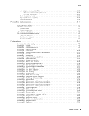
5061 Low voltage power supply (LVPS 5-23 LVPS cable connectors to system board 5-23 LVPS fuser connectors 5-24 Media size sensing board 5-25 High-capacity input tray (HCIT 5-26 StapleSmart ...
5061 Low voltage power supply (LVPS 5-23 LVPS cable connectors to system board 5-23 LVPS fuser connectors 5-24 Media size sensing board 5-25 High-capacity input tray (HCIT 5-26 StapleSmart ...
Service Manual
Page 41
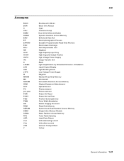
...-Capacity Input Tray High-Capacity Output Finisher High Voltage Power Supply Image Transfer Unit Black Light Amplification by Stimulated Emission of Radiation Liquid Crystal Display Light-Emitting Diode Low Voltage Power Supply Magenta Masked Read Only Memory Microswitch Nonvolatile Random Access... Memory Original Equipment Manufacturer Optical Sensor Photoconductor Picture element Power-On Reset Power-On Self Test Position Sensing Device Pulse Width ...
...-Capacity Input Tray High-Capacity Output Finisher High Voltage Power Supply Image Transfer Unit Black Light Amplification by Stimulated Emission of Radiation Liquid Crystal Display Light-Emitting Diode Low Voltage Power Supply Magenta Masked Read Only Memory Microswitch Nonvolatile Random Access... Memory Original Equipment Manufacturer Optical Sensor Photoconductor Picture element Power-On Reset Power-On Self Test Position Sensing Device Pulse Width ...
Service Manual
Page 54
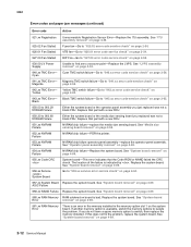
... Fan-Go to find zero crossover point-Replace the LVPS. Cyan 941.xx TMC Error- See "System board removal" on page 2-55. 930.09 LV Power Supply Unable to "927.03 error code service check" on page 4-89. ASIC Failure 958.xx NAND Failure Replace the system board. Replace the system board...
... Fan-Go to find zero crossover point-Replace the LVPS. Cyan 941.xx TMC Error- See "System board removal" on page 2-55. 930.09 LV Power Supply Unable to "927.03 error code service check" on page 4-89. ASIC Failure 958.xx NAND Failure Replace the system board. Replace the system board...
Service Manual
Page 99
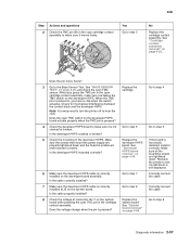
... "BASE SENSOR TEST" on page 4-39. Check for mechanical interference between the contact block and the developer HVPS. Make sure the screws that mount the power supply are tightened down and the board is incorrectly installed, install it moves freely. Go to make sure it correctly. Go to step 4 Go to step...
... "BASE SENSOR TEST" on page 4-39. Check for mechanical interference between the contact block and the developer HVPS. Make sure the screws that mount the power supply are tightened down and the board is incorrectly installed, install it moves freely. Go to make sure it correctly. Go to step 4 Go to step...
Service Manual
Page 101
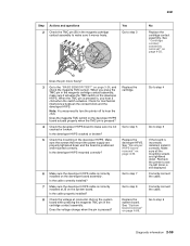
... HVPS board to make sure it actuates the TMC switch on the system board. Correctly connect the cable. Make sure the screws that mount the power supply are tightened down and the board is correctly installed on page 4-89. Is the developer HVPS mounted correctly? 6 Make sure the developer HVPS cable is...
... HVPS board to make sure it actuates the TMC switch on the system board. Correctly connect the cable. Make sure the screws that mount the power supply are tightened down and the board is correctly installed on page 4-89. Is the developer HVPS mounted correctly? 6 Make sure the developer HVPS cable is...

Service Manual
Page 103
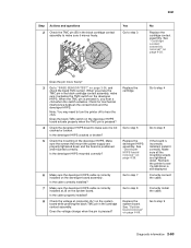
... when the TMC pin is correctly installed at connector J6-16 on the developer HVPS. Replace the cartridge. Make sure the screws that mount the power supply are tightened down and the board is correctly installed on page 3-24, and check the yellow TMC sensor.
... when the TMC pin is correctly installed at connector J6-16 on the developer HVPS. Replace the cartridge. Make sure the screws that mount the power supply are tightened down and the board is correctly installed on page 3-24, and check the yellow TMC sensor.
Service Manual
Page 105
... mounting screws are properly tightened down . Does the pin move freely? 3 Go to step 8 Replace the system board. Make sure the screws that mount the power supply are tightened down and the board is still displayed. Recheck the printer to step 5 If the board is correctly installed on page 3-24, and check...
... mounting screws are properly tightened down . Does the pin move freely? 3 Go to step 8 Replace the system board. Make sure the screws that mount the power supply are tightened down and the board is still displayed. Recheck the printer to step 5 If the board is correctly installed on page 3-24, and check...
Service Manual
Page 116
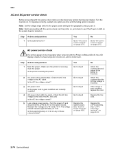
... Turn the machine on J18-3 and J18-4. Measure the voltages on . If it operates correctly, reattach one option at J18 on the system board. AC power service check The printer appears to be installed. Note: Set the voltage range switch to step 5 Replace the system board. Replace the line cord. Step... when turned on with this service check, turn . See "LVPS assembly removal" on page 4-89. Is the AC line voltage correct? 5 Low voltage power supply-Turn the power off , the LCD display is blank, the fuser lamps do not come on, and no motors turn the printer on, and check to "DC...
... Turn the machine on J18-3 and J18-4. Measure the voltages on . If it operates correctly, reattach one option at J18 on the system board. AC power service check The printer appears to be installed. Note: Set the voltage range switch to step 5 Replace the system board. Replace the line cord. Step... when turned on with this service check, turn . See "LVPS assembly removal" on page 4-89. Is the AC line voltage correct? 5 Low voltage power supply-Turn the power off , the LCD display is blank, the fuser lamps do not come on, and no motors turn the printer on, and check to "DC...

Service Manual
Page 151
... 1 2 3 Actions and questions Second transfer roll assembly-Check the second transfer roll for damage, toner, or foreign material. Transfer high voltage power supply, HV wiring, and contacts-Check the second transfer cable (transfer HVPS contact to the second transfer roll rear arm contact) for service. See ... to the roll, oil, or other contaminants on page 4-88. Second transfer roll service check Note: The second transfer roll is powered off before making any signs of the roll. Contact your next level of support. Is there any problems with the associated hardware? Go...
... 1 2 3 Actions and questions Second transfer roll assembly-Check the second transfer roll for damage, toner, or foreign material. Transfer high voltage power supply, HV wiring, and contacts-Check the second transfer cable (transfer HVPS contact to the second transfer roll rear arm contact) for service. See ... to the roll, oil, or other contaminants on page 4-88. Second transfer roll service check Note: The second transfer roll is powered off before making any signs of the roll. Contact your next level of support. Is there any problems with the associated hardware? Go...
Service Manual
Page 183
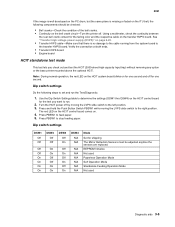
... right position. The red LED on the HCIT control board comes on the ITU belt, the following steps to set and run . 2. Turn the HCIT power off . Dip switch settings DSW1 Off Off Off Off On On On On DSW2 Off Off On On Off Off On On DSW3 Off On... the HCIT (2000-sheet high capacity Input tray) without removing any option or the base printer mounted above the optional HCIT. See "Transfer high voltage power supply (HVPS)" on page 5-20. • Transfer HVPS cable-Make sure that there is missing or faded on . 4.
... right position. The red LED on the HCIT control board comes on the ITU belt, the following steps to set and run . 2. Turn the HCIT power off . Dip switch settings DSW1 Off Off Off Off On On On On DSW2 Off Off On On Off Off On On DSW3 Off On... the HCIT (2000-sheet high capacity Input tray) without removing any option or the base printer mounted above the optional HCIT. See "Transfer high voltage power supply (HVPS)" on page 5-20. • Transfer HVPS cable-Make sure that there is missing or faded on . 4.
Service Manual
Page 321
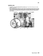
Repair information 4-93 This makes sure the toroid (G) does not come into contact with the motor when the card is in place. 5061 Installation notes • To identify the color coded cable bands to the connectors, see "Transfer high voltage power supply (HVPS)" on page 5-20. • When installing the transfer HVPS board, route the cable to the HVPS input connector at CN1 (C) over the cable to the yellow transfer contact (D), under the cable to the magenta transfer contact (E), and attached to the cable tie (F).
Repair information 4-93 This makes sure the toroid (G) does not come into contact with the motor when the card is in place. 5061 Installation notes • To identify the color coded cable bands to the connectors, see "Transfer high voltage power supply (HVPS)" on page 5-20. • When installing the transfer HVPS board, route the cable to the HVPS input connector at CN1 (C) over the cable to the yellow transfer contact (D), under the cable to the magenta transfer contact (E), and attached to the cable tie (F).
Service Manual
Page 344
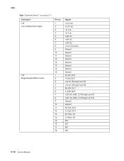
5061 See "System board" on page 5-7. Connector J18 Low voltage power supply J19 Magenta/cyan BLDC motors Pin no. 1 2 3 4 5 6 7 8 9 10 11 12 13 14 15 16 1 2 3 4 5 6 7 8 9 10 11 12 13 14 15 16 17 18 Signal +3.3 V dc +3.3 V dc +5 V dc +5 V dc +24V dc +24V dc +24V dc +3.3 V dc Sense Ground Ground Ground Ground Ground Ground Ground Ground M_ON_OUT C_ON_OUT +5V dc (Through fuse F8) +5V dc (Through fuse F8) M_DIR_OUT C_DIR_OUT +24V_M_AND_C (Through fuse F5) +24V_M_AND_C (Through fuse F5) Ground Ground M_CLK_OUT C_CLK_OUT M_HALL_IN C_HALL_IN N/C N/C N/C N/C 5-12 Service Manual
5061 See "System board" on page 5-7. Connector J18 Low voltage power supply J19 Magenta/cyan BLDC motors Pin no. 1 2 3 4 5 6 7 8 9 10 11 12 13 14 15 16 1 2 3 4 5 6 7 8 9 10 11 12 13 14 15 16 17 18 Signal +3.3 V dc +3.3 V dc +5 V dc +5 V dc +24V dc +24V dc +24V dc +3.3 V dc Sense Ground Ground Ground Ground Ground Ground Ground Ground M_ON_OUT C_ON_OUT +5V dc (Through fuse F8) +5V dc (Through fuse F8) M_DIR_OUT C_DIR_OUT +24V_M_AND_C (Through fuse F5) +24V_M_AND_C (Through fuse F5) Ground Ground M_CLK_OUT C_CLK_OUT M_HALL_IN C_HALL_IN N/C N/C N/C N/C 5-12 Service Manual
Service Manual
Page 346
... Ground +5 V dc (through fuse F12 and safety switches at J10) C_LENA Ground C_THERMISTOR Y_DATAGround Y_DATA+ FAN1_STALL_IN Ground FAN1_CNTRL +24V_LEFTSIDE Ground +5 V dc (direct from low voltage power supply) Ground VDO_ERR (+5 V dc to J8 and J12) 5-14 Service Manual
... Ground +5 V dc (through fuse F12 and safety switches at J10) C_LENA Ground C_THERMISTOR Y_DATAGround Y_DATA+ FAN1_STALL_IN Ground FAN1_CNTRL +24V_LEFTSIDE Ground +5 V dc (direct from low voltage power supply) Ground VDO_ERR (+5 V dc to J8 and J12) 5-14 Service Manual
Service Manual
Page 354
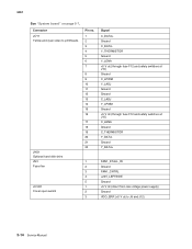
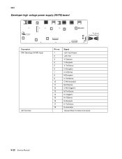
5061 Developer high voltage power supply (HVPS) board Connector CN1 Developer HVPS Input CB Terminal Pin no 1 2 3 4 5 6 7 8 9 10 11 12 13 14 15 16 17 18 Signal +24 V dc Return +24 V dc Y-Ctsense Y-Devpwm Y-TnrSense C-Devpwm C-CtSense M-Devpwm C-TnrSense CYM-Acenable M-CtSense CYM-Chgpwm M-TnrSense K-Chgpwm K-CtSense K-Devpwm K-TnrSense K-Acenable Cleaner Bias Terminal (not used) 5-22 Service Manual
5061 Developer high voltage power supply (HVPS) board Connector CN1 Developer HVPS Input CB Terminal Pin no 1 2 3 4 5 6 7 8 9 10 11 12 13 14 15 16 17 18 Signal +24 V dc Return +24 V dc Y-Ctsense Y-Devpwm Y-TnrSense C-Devpwm C-CtSense M-Devpwm C-TnrSense CYM-Acenable M-CtSense CYM-Chgpwm M-TnrSense K-Chgpwm K-CtSense K-Devpwm K-TnrSense K-Acenable Cleaner Bias Terminal (not used) 5-22 Service Manual
Service Manual
Page 355
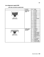
5061 Low voltage power supply (LVPS) LVPS cable connectors to system board Connector Main power to system board (J35) LVPS to system board cable for fuser (J17) Pin Signal 1 +3.3 V dc 2 +3.3 V dc 3 +5 V dc 4 +5 V dc 5 +24 V dc 6 +24 V dc 7 +24 V dc 8 +3.3 V dc ...
5061 Low voltage power supply (LVPS) LVPS cable connectors to system board Connector Main power to system board (J35) LVPS to system board cable for fuser (J17) Pin Signal 1 +3.3 V dc 2 +3.3 V dc 3 +5 V dc 4 +5 V dc 5 +24 V dc 6 +24 V dc 7 +24 V dc 8 +3.3 V dc ...
Service Manual
Page 363
...Go to help prevent problems and maintain optimum performance. Preventive maintenance This chapter describes procedures for part number. If any non-Lexmark attachments Scheduled maintenance The operator panel displays 80 Fuser Maintenance and 83 ITU Maintenance for 2xx and 4xx models Part number 40X1788..., or altered parts, especially in the area of the On/Off switch and the power supply • Damaged, missing, or altered covers, especially in the area of the top cover and the power supply cover • Possible safety exposure from any unsafe conditions exist, find out how serious...
...Go to help prevent problems and maintain optimum performance. Preventive maintenance This chapter describes procedures for part number. If any non-Lexmark attachments Scheduled maintenance The operator panel displays 80 Fuser Maintenance and 83 ITU Maintenance for 2xx and 4xx models Part number 40X1788..., or altered parts, especially in the area of the On/Off switch and the power supply • Damaged, missing, or altered covers, especially in the area of the top cover and the power supply cover • Possible safety exposure from any unsafe conditions exist, find out how serious...

Service Manual
Page 400
... Screw type 323, parts packet, 40X1633 (TFR HVPS board to frame) Screw type 324, parts packet, 40X1635 (TFR HVPS board to frame) Standoff, high voltage power supply-developer board Screw type 121, parts packet, 40X1780 Developer HVPS board-1xx/3xx only Also order cable tie parts packet (P/N 40X1648) Developer HVPS board-2xx...
... Screw type 323, parts packet, 40X1633 (TFR HVPS board to frame) Screw type 324, parts packet, 40X1635 (TFR HVPS board to frame) Standoff, high voltage power supply-developer board Screw type 121, parts packet, 40X1780 Developer HVPS board-1xx/3xx only Also order cable tie parts packet (P/N 40X1648) Developer HVPS board-2xx...


