

Lenovo V370 Hardware Maintenance Manual
Page 3
... management 25 Screen blank mode 25 Sleep (standby) mode 25 Hibernation mode 26 Lenovo V370 27 Specifications 27 Status indicators 29 Fn key combinations 31 FRU replacement notices 32 Screw notices 32 Removing and replacing an FRU 33 1010 Battery pack 34 1020 Dummy card 35 1030 Hard disk drive(HDD)/Memory/Mini...
... management 25 Screen blank mode 25 Sleep (standby) mode 25 Hibernation mode 26 Lenovo V370 27 Specifications 27 Status indicators 29 Fn key combinations 31 FRU replacement notices 32 Screw notices 32 Removing and replacing an FRU 33 1010 Battery pack 34 1020 Dummy card 35 1030 Hard disk drive(HDD)/Memory/Mini...

Lenovo V370 Hardware Maintenance Manual
Page 9
...task. Insulation must determine how serious the apparent hazard could be frayed or worn. 4. Checklist: 1. Check exterior covers for cracked or bulging batteries. 5. Disconnect the power cord. 3. Check for : a. Safety information Safety inspection guide The purpose of this inspection guide. Check the ...unsafe conditions. Check for 0.1 ohm or less between the external ground pin and the frame ground. If any unsafe conditions are any non-Lenovo alterations. 7. c. Begin the checks with . 5 b. As each machine was designed and built, required safety items were installed to ...
...task. Insulation must determine how serious the apparent hazard could be frayed or worn. 4. Checklist: 1. Check exterior covers for cracked or bulging batteries. 5. Disconnect the power cord. 3. Check for : a. Safety information Safety inspection guide The purpose of this inspection guide. Check the ...unsafe conditions. Check for 0.1 ohm or less between the external ground pin and the frame ground. If any unsafe conditions are any non-Lenovo alterations. 7. c. Begin the checks with . 5 b. As each machine was designed and built, required safety items were installed to ...

Lenovo V370 Hardware Maintenance Manual
Page 10
... strap against ESD damage by a certified electrician. 6 The mat is required for operator safety and correct system function. When working on a double-insulated or battery-operated system, use coax or connectoroutside shells on these systems. - You can occur when there is desirable but not necessary. - Use the round ground prong... from touching your skin to provide protection that meets the specific service requirement. ESD damage can use an ESD common ground or reference point. Lenovo V370 Hardware Maintenance Manual Handling devices that are all at the same charge.
... strap against ESD damage by a certified electrician. 6 The mat is required for operator safety and correct system function. When working on a double-insulated or battery-operated system, use coax or connectoroutside shells on these systems. - You can occur when there is desirable but not necessary. - Use the round ground prong... from touching your skin to provide protection that meets the specific service requirement. ESD damage can use an ESD common ground or reference point. Lenovo V370 Hardware Maintenance Manual Handling devices that are all at the same charge.

Lenovo V370 Hardware Maintenance Manual
Page 25
...0 2 1 Note: Output voltage for correct continuity and installation. •• If the computer does not charge during operation, use a discharged battery pack or a battery pack that power is acceptable, do the following power supply checkouts: •• "Checking the AC adapter " on page 21 ••...charging" on page 21 •• "Checking the battery pack " on page 22 Checking the AC adapter You are servicing. 3. Checking operational charging To check whether the battery charges properly during operation, go to "Lenovo V370" on , check the power cord of the AC ...
...0 2 1 Note: Output voltage for correct continuity and installation. •• If the computer does not charge during operation, use a discharged battery pack or a battery pack that power is acceptable, do the following power supply checkouts: •• "Checking the AC adapter " on page 21 ••...charging" on page 21 •• "Checking the battery pack " on page 22 Checking the AC adapter You are servicing. 3. Checking operational charging To check whether the battery charges properly during operation, go to "Lenovo V370" on , check the power cord of the AC ...
Lenovo V370 Hardware Maintenance Manual
Page 26
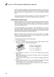
...least 3 hours, even though the indicator does not light on. Remove the battery pack and measure the voltage between battery terminals 5 and 7. If the voltage is more than +11.0 V DC, the battery pack has been discharged. If the voltage is less than +11.0 V...1 +0 to room temperature. If the battery status indicator or icon does not light on , replace the system board. If the charge indicator or icon is still less than 95% of its capacity. Note: Recharging will be 4 to 100% of the total power remains; Lenovo V370 Hardware Maintenance Manual Perform operational charging.
...least 3 hours, even though the indicator does not light on. Remove the battery pack and measure the voltage between battery terminals 5 and 7. If the voltage is more than +11.0 V DC, the battery pack has been discharged. If the voltage is less than +11.0 V...1 +0 to room temperature. If the battery status indicator or icon does not light on , replace the system board. If the charge indicator or icon is still less than 95% of its capacity. Note: Recharging will be 4 to 100% of the total power remains; Lenovo V370 Hardware Maintenance Manual Perform operational charging.
Lenovo V370 Hardware Maintenance Manual
Page 29
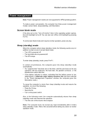
... what occurs in screen blank mode: •• The LCD is powered off. •• The hard disk drive is low. (Alternatively, if Hibernate when battery becomes low has been selected in the operating system expires, the LCD backlight turns off. To enter sleep (standby) mode, press Fn+F1. You can... does not accept any operation with the keyboard, the hard disk, the parallel connector, or the diskette drive within that time. •• If the battery indicator is amber, indicating that the battery power is powered off the LCD backlight by pressing Fn+F2.
... what occurs in screen blank mode: •• The LCD is powered off. •• The hard disk drive is low. (Alternatively, if Hibernate when battery becomes low has been selected in the operating system expires, the LCD backlight turns off. To enter sleep (standby) mode, press Fn+F1. You can... does not accept any operation with the keyboard, the hard disk, the parallel connector, or the diskette drive within that time. •• If the battery indicator is amber, indicating that the battery power is powered off the LCD backlight by pressing Fn+F2.

Lenovo V370 Hardware Maintenance Manual
Page 32
Lenovo V370 Hardware Maintenance Manual Table 1. Specifications (continued) Feature I/O port MODEM slot Audio Video Ethernet (on the system board) PCI Express Mini Card slot Bluetooth wireless Keyboard Touch pad Fingerprint reader Integrated camera Battery AC adapter Pre-installed operating system Description • Stereo headphone ... (full size) (Select models only) • Built-in antenna with min-USB interface, Select models only • 6-row Lenovo Keyboard • Multi-touch touchpad • Select models only • 2.0Million pixels, HD (option), Fixed Focus CMOS camera • ...
Lenovo V370 Hardware Maintenance Manual Table 1. Specifications (continued) Feature I/O port MODEM slot Audio Video Ethernet (on the system board) PCI Express Mini Card slot Bluetooth wireless Keyboard Touch pad Fingerprint reader Integrated camera Battery AC adapter Pre-installed operating system Description • Stereo headphone ... (full size) (Select models only) • Built-in antenna with min-USB interface, Select models only • 6-row Lenovo Keyboard • Multi-touch touchpad • Select models only • 2.0Million pixels, HD (option), Fixed Focus CMOS camera • ...

Lenovo V370 Hardware Maintenance Manual
Page 34
... one of the wireless devices (WLAN/Bluetooth) is less than 5% of its capacity. Lenovo V370 Hardware Maintenance Manual Table 2. White: The remaining power of the battery is more than 80% of its capacity, or the computer is operating on ) The battery is being charged with the remaining power between 5% and 20% of its capacity...
... one of the wireless devices (WLAN/Bluetooth) is less than 5% of its capacity. Lenovo V370 Hardware Maintenance Manual Table 2. White: The remaining power of the battery is more than 80% of its capacity, or the computer is operating on ) The battery is being charged with the remaining power between 5% and 20% of its capacity...

Lenovo V370 Hardware Maintenance Manual
Page 37
... reverse the removal procedures and follow any of the notes that have made sure that all power cords from electrical outlets, remove the battery pack, and then disconnect any computer unless you have to be damaged by touching a ground point with the instructions to indicate how to...Metallic parts or metal flakes can be removed before the failing FRU. Any of such FRUs are listed at the top of damaging parts. 2. Lenovo V370 Removing and replacing an FRU This section presents exploded figures with one hand or using an electrostatic discharge (ESD) strap (P/N 6405959) to remove ...
... reverse the removal procedures and follow any of the notes that have made sure that all power cords from electrical outlets, remove the battery pack, and then disconnect any computer unless you have to be damaged by touching a ground point with the instructions to indicate how to...Metallic parts or metal flakes can be removed before the failing FRU. Any of such FRUs are listed at the top of damaging parts. 2. Lenovo V370 Removing and replacing an FRU This section presents exploded figures with one hand or using an electrostatic discharge (ESD) strap (P/N 6405959) to remove ...

Lenovo V370 Hardware Maintenance Manual
Page 38
Then make sure that the battery release lever is in the direction shown by arrow 3. 1 3 2 When installing: Install the battery pack along the slide rails of battery pack Unlock the battery release lever 1. Any other battery could ignite or explode. Figure 1. Holding the battery release lever in the unlocked position 2, remove the battery pack in the locked position. 34 Removal steps of the slot. Lenovo V370 Hardware Maintenance Manual 1010 Battery pack DANGER Only use the battery specified in the parts list for your computer.
Then make sure that the battery release lever is in the direction shown by arrow 3. 1 3 2 When installing: Install the battery pack along the slide rails of battery pack Unlock the battery release lever 1. Any other battery could ignite or explode. Figure 1. Holding the battery release lever in the unlocked position 2, remove the battery pack in the locked position. 34 Removal steps of the slot. Lenovo V370 Hardware Maintenance Manual 1010 Battery pack DANGER Only use the battery specified in the parts list for your computer.

Lenovo V370 Hardware Maintenance Manual
Page 39
Removal steps of dummy cards Remove the dummy card in the direction shown by arrows 1 2. 1 2 35 Lenovo V370 1020 Dummy card For access, remove this FRU: •• "1010 Battery pack" on page 34 Figure 2.
Removal steps of dummy cards Remove the dummy card in the direction shown by arrows 1 2. 1 2 35 Lenovo V370 1020 Dummy card For access, remove this FRU: •• "1010 Battery pack" on page 34 Figure 2.

Lenovo V370 Hardware Maintenance Manual
Page 40
Lenovo V370 Hardware Maintenance Manual 1030 Hard disk drive(HDD)/Memory/Mini PCI Express Card slot compartment cover For access, remove this FRU: •• "1010 Battery pack" on page 34 Figure 3. Removal steps of HDD/Memory/Mini PCI Express Card slot compartment cover Loosen three screws 1, but do not remove them. 1 1 1 2 36
Lenovo V370 Hardware Maintenance Manual 1030 Hard disk drive(HDD)/Memory/Mini PCI Express Card slot compartment cover For access, remove this FRU: •• "1010 Battery pack" on page 34 Figure 3. Removal steps of HDD/Memory/Mini PCI Express Card slot compartment cover Loosen three screws 1, but do not remove them. 1 1 1 2 36

Lenovo V370 Hardware Maintenance Manual
Page 41
...: Make sure that the HDD connector is in suspend mode. Lenovo V370 1040 Hard disk drive For access, remove these FRUs in the direction shown by arrow 2, and then remove the hard disk drive from the slot in order: •• "1010 Battery pack" on page 34 •• "1030 Hard disk drive...
...: Make sure that the HDD connector is in suspend mode. Lenovo V370 1040 Hard disk drive For access, remove these FRUs in the direction shown by arrow 2, and then remove the hard disk drive from the slot in order: •• "1010 Battery pack" on page 34 •• "1030 Hard disk drive...
Lenovo V370 Hardware Maintenance Manual
Page 42
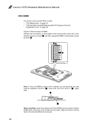
... arrows 1, and then unplug the DIMM in the direction shown by arrow 2. 1 2 1 Note: If only one DIMM is firmly fixed in order: •• "1010 Battery pack" on page 34 •• "1030 Hard disk drive(HDD)/Memory/Mini PCI Express Card slot compartment cover" on page 36 Figure 6. Push the... firmly, and pivot it until it is used on both edges of the DIMM into the place. Make sure that it snaps into the socket. Lenovo V370 Hardware Maintenance Manual 1050 DIMM For access, remove these FRUs in the slot and difficult to be installed in SLOT-0 ( a : lower slot), but not in...
... arrows 1, and then unplug the DIMM in the direction shown by arrow 2. 1 2 1 Note: If only one DIMM is firmly fixed in order: •• "1010 Battery pack" on page 34 •• "1030 Hard disk drive(HDD)/Memory/Mini PCI Express Card slot compartment cover" on page 36 Figure 6. Push the... firmly, and pivot it until it is used on both edges of the DIMM into the place. Make sure that it snaps into the socket. Lenovo V370 Hardware Maintenance Manual 1050 DIMM For access, remove these FRUs in the slot and difficult to be installed in SLOT-0 ( a : lower slot), but not in...

Lenovo V370 Hardware Maintenance Manual
Page 43
... 2 cables in order: •• "1010 Battery pack" on page 34 •• "1030 Hard disk drive(HDD)/Memory/Mini PCI Express Card slot compartment cover" on page 36 Figure 7. Step 2 Screw (quantity) M2 × 3 mm, flat-head, nylok-coated (1) Color Black Torque 1.6 kgfcm 39 Lenovo V370 1060 PCI Express Mini Card for...
... 2 cables in order: •• "1010 Battery pack" on page 34 •• "1030 Hard disk drive(HDD)/Memory/Mini PCI Express Card slot compartment cover" on page 36 Figure 7. Step 2 Screw (quantity) M2 × 3 mm, flat-head, nylok-coated (1) Color Black Torque 1.6 kgfcm 39 Lenovo V370 1060 PCI Express Mini Card for...
Lenovo V370 Hardware Maintenance Manual
Page 45
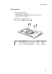
Removal steps of keyboard Remove three screws 1 and one screw 2. 12 1 1 Step 1 2 Screw (quantity) M2.5 × 8 mm, flat-head, nylok-coated (3) M2 × 5 mm, flat-head, nylok-coated (1) Color Black Black Torque 3.0 kgfcm 3.0 kgfcm 41 Lenovo V370 1070 Keyboard For access, remove this FRU: •• "1010 Battery pack" on page 34 •• "1030 Hard disk drive(HDD)/Memory/Mini PCI Express Card slot compartment cover" on page 36 Figure 8.
Removal steps of keyboard Remove three screws 1 and one screw 2. 12 1 1 Step 1 2 Screw (quantity) M2.5 × 8 mm, flat-head, nylok-coated (3) M2 × 5 mm, flat-head, nylok-coated (1) Color Black Black Torque 3.0 kgfcm 3.0 kgfcm 41 Lenovo V370 1070 Keyboard For access, remove this FRU: •• "1010 Battery pack" on page 34 •• "1030 Hard disk drive(HDD)/Memory/Mini PCI Express Card slot compartment cover" on page 36 Figure 8.
Lenovo V370 Hardware Maintenance Manual
Page 47
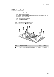
Removal steps of keyboard bezel Remove twelve screws 1 on page 41 Figure 9. Lenovo V370 1080 Keyboard bezel For access, remove these FRUs in order: •• "1010 Battery pack" on page 34 •• "1030 Hard disk drive(HDD)/Memory/Mini PCI Express Card slot compartment cover" on page 36 •• "1040 Hard disk drive" on page 37 •• "1070 Keyboard" on the bottom. 11 1 1 1 1 1 1 1 1 1 1 Step 1 Screw (quantity) Color M2.5 × 8 mm, flat-head, nylok-coated (12) Black Torque 3.0 kgfcm 43
Removal steps of keyboard bezel Remove twelve screws 1 on page 41 Figure 9. Lenovo V370 1080 Keyboard bezel For access, remove these FRUs in order: •• "1010 Battery pack" on page 34 •• "1030 Hard disk drive(HDD)/Memory/Mini PCI Express Card slot compartment cover" on page 36 •• "1040 Hard disk drive" on page 37 •• "1070 Keyboard" on the bottom. 11 1 1 1 1 1 1 1 1 1 1 Step 1 Screw (quantity) Color M2.5 × 8 mm, flat-head, nylok-coated (12) Black Torque 3.0 kgfcm 43

Lenovo V370 Hardware Maintenance Manual
Page 52
Lenovo V370 Hardware Maintenance Manual 1090 System board Important notices for wireless LAN" on page 39 •• "1070 Keyboard" on page 41 •• "1080 Keyboard bezel" on a padded surface such as an ESD mat or conductive corrugated material. For access, remove these FRUs in order: •• "1010 Battery pack" on page...
Lenovo V370 Hardware Maintenance Manual 1090 System board Important notices for wireless LAN" on page 39 •• "1070 Keyboard" on page 41 •• "1080 Keyboard bezel" on a padded surface such as an ESD mat or conductive corrugated material. For access, remove these FRUs in order: •• "1010 Battery pack" on page...
Lenovo V370 Hardware Maintenance Manual
Page 55
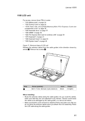
... the cables to be damaged by arrows 1. Removal steps of LCD unit Release the antenna cables from the cable guides in order: •• "1010 Battery pack" on page 34 •• "1020 Dummy card" on page 35 •• "1030 Hard disk drive(HDD)/Memory/Mini PCI Express Card slot... •• "1070 Keyboard" on page 41 •• "1080 Keyboard bezel" on page 43 •• "1090 System board" on page 48 Figure 11. Lenovo V370 1100 LCD unit For access, remove these FRUs in the direction shown by the cable guides, or a wire to be broken. •• Make sure...
... the cables to be damaged by arrows 1. Removal steps of LCD unit Release the antenna cables from the cable guides in order: •• "1010 Battery pack" on page 34 •• "1020 Dummy card" on page 35 •• "1030 Hard disk drive(HDD)/Memory/Mini PCI Express Card slot... •• "1070 Keyboard" on page 41 •• "1080 Keyboard bezel" on page 43 •• "1090 System board" on page 48 Figure 11. Lenovo V370 1100 LCD unit For access, remove these FRUs in the direction shown by the cable guides, or a wire to be broken. •• Make sure...

Lenovo V370 Hardware Maintenance Manual
Page 57
Removal steps of fan assembly and heat sink assembly Note: Detach the fan connector in order: •• "1010 Battery pack" on page 34 •• "1020 Dummy card" on page 35 •• "1030 Hard disk drive(HDD)/Memory/Mini PCI Express Card slot ... •• "1070 Keyboard" on page 41 •• "1080 Keyboard bezel" on page 43 •• "1090 System board" on page 48 Figure 12. Lenovo V370 1110 Fan assembly and Heat Sink assembly For access, remove these FRUs in the direction shown by arrow 1. 1 When installing: Make sure that the fan...
Removal steps of fan assembly and heat sink assembly Note: Detach the fan connector in order: •• "1010 Battery pack" on page 34 •• "1020 Dummy card" on page 35 •• "1030 Hard disk drive(HDD)/Memory/Mini PCI Express Card slot ... •• "1070 Keyboard" on page 41 •• "1080 Keyboard bezel" on page 43 •• "1090 System board" on page 48 Figure 12. Lenovo V370 1110 Fan assembly and Heat Sink assembly For access, remove these FRUs in the direction shown by arrow 1. 1 When installing: Make sure that the fan...


