User Manual
Page 5
...product ventilation x Operating environment xi Electrical current safety information xi Lithium battery notice xii Modem safety information xii Laser compliance statement xiii Power supply statement xiii Products with television tuner options installed . . iii v General safety guidelines vi Service and upgrades vi Static electricity prevention vii... 1 Air circulation 2 Electrical outlets and cable lengths 2 Chapter 2. Contents Important safety information v Conditions that require immediate action . . . . . Troubleshooting and diagnostics 55 © Lenovo 2006, 2007.
...product ventilation x Operating environment xi Electrical current safety information xi Lithium battery notice xii Modem safety information xii Laser compliance statement xiii Power supply statement xiii Products with television tuner options installed . . iii v General safety guidelines vi Service and upgrades vi Static electricity prevention vii... 1 Air circulation 2 Electrical outlets and cable lengths 2 Chapter 2. Contents Important safety information v Conditions that require immediate action . . . . . Troubleshooting and diagnostics 55 © Lenovo 2006, 2007.

User Manual
Page 8
See Chapter 8, "Getting information, help, and service," on the battery. v Power cords, plugs, power adapters, extension cords, surge protectors, or power supplies that are zero. v Damage to a battery (such as an extension cord) that is approved to repair your particular product. ... approved for further guidance. Although there are required for customers to install options or replace CRUs. Lenovo provides documentation with an ac power cord, always make sure that the power is turned off and that the product is appropriate for your product, stop using the product and...
See Chapter 8, "Getting information, help, and service," on the battery. v Power cords, plugs, power adapters, extension cords, surge protectors, or power supplies that are zero. v Damage to a battery (such as an extension cord) that is approved to repair your particular product. ... approved for further guidance. Although there are required for customers to install options or replace CRUs. Lenovo provides documentation with an ac power cord, always make sure that the power is turned off and that the product is appropriate for your product, stop using the product and...

User Manual
Page 11
... adapter or to obtain a replacement. Never overload an electrical outlet. Batteries supplied by Lenovo for more information if you have questions about power loads and branch circuit ratings. If power strips are used, the load should not exceed 80 percent of electricity; ... and current for more information if you have questions about power loads, power requirements, and input ratings. Extension cords and related devices Ensure that extension cords, surge protectors, uninterruptible power supplies, and power strips that you use are rated to insert it is replaced...
... adapter or to obtain a replacement. Never overload an electrical outlet. Batteries supplied by Lenovo for more information if you have questions about power loads and branch circuit ratings. If power strips are used, the load should not exceed 80 percent of electricity; ... and current for more information if you have questions about power loads, power requirements, and input ratings. Extension cords and related devices Ensure that extension cords, surge protectors, uninterruptible power supplies, and power strips that you use are rated to insert it is replaced...
User Manual
Page 12
...in the product documentation. Inspect your computer more frequently. If you notice any part of the computer including heat sink inlet fins, power supply vents, and fans. v Do not restrict or block any battery. then remove any perforations in or near flammable materials or in...increase the risk of high-traffic areas. v Do not store or operate your computer inside of your computer, turn off the power and unplug the computer's power cord from vents and perforations in explosive environments. v Airflow temperatures into the computer should not exceed 35° C (95&#...
...in the product documentation. Inspect your computer more frequently. If you notice any part of the computer including heat sink inlet fins, power supply vents, and fans. v Do not restrict or block any battery. then remove any perforations in or near flammable materials or in...increase the risk of high-traffic areas. v Do not store or operate your computer inside of your computer, turn off the power and unplug the computer's power cord from vents and perforations in explosive environments. v Airflow temperatures into the computer should not exceed 35° C (95&#...
User Manual
Page 15
... with optical instruments, and avoid direct exposure to hazardous laser radiation. Important safety information xiii to conform to be installed in the U.S. Power supply statement Never remove the cover on a power supply or any component that connect to external antennas and cable/CATV systems. If local codes are not applicable, it is installed, note...
... with optical instruments, and avoid direct exposure to hazardous laser radiation. Important safety information xiii to conform to be installed in the U.S. Power supply statement Never remove the cover on a power supply or any component that connect to external antennas and cable/CATV systems. If local codes are not applicable, it is installed, note...
User Manual
Page 35
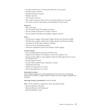
... PCI Express x1 adapter connector v One low-profile PCI Express x16 graphics adapter connector Power v 180 Watt power supply with manual voltage selection switch (some models) v 220 Watt power supply with preinstalled software. If it does, an operating system, device drivers to secure the... might come with manual voltage selection switch (some models) v Automatic 50/60 Hz input frequency switching v Advanced Power Management support v Advanced Configuration and Power Interface (ACPI) support Security features v User and administrator passwords for BIOS access v Support for the addition of...
... PCI Express x1 adapter connector v One low-profile PCI Express x16 graphics adapter connector Power v 180 Watt power supply with manual voltage selection switch (some models) v 220 Watt power supply with preinstalled software. If it does, an operating system, device drivers to secure the... might come with manual voltage selection switch (some models) v Automatic 50/60 Hz input frequency switching v Advanced Power Management support v Advanced Configuration and Power Interface (ACPI) support Security features v User and administrator passwords for BIOS access v Support for the addition of...

User Manual
Page 37
Some models do not have a switchable power supply that supports both low and high input voltage ranges. See "Voltage-selection switch" on page viii for your computer. Input voltage: Low range: Minimum: 100 V ...
Some models do not have a switchable power supply that supports both low and high input voltage ranges. See "Voltage-selection switch" on page viii for your computer. Input voltage: Low range: Minimum: 100 V ...

User Manual
Page 43
Installing options 23 Locating components The following illustration will help you locate the various components in your computer. 1 Optical drive 2 Diskette drive 3 Memory modules 4 Battery 5 Power supply 6 PCI adapter connector 7 PCI Express x16 graphics adapter or PCI Express x1 adapter connector (some models) 8 PCI Express x1 adapter connector or PCI Express x16 graphics adapter (some models) Chapter 3.
Installing options 23 Locating components The following illustration will help you locate the various components in your computer. 1 Optical drive 2 Diskette drive 3 Memory modules 4 Battery 5 Power supply 6 PCI adapter connector 7 PCI Express x16 graphics adapter or PCI Express x1 adapter connector (some models) 8 PCI Express x1 adapter connector or PCI Express x16 graphics adapter (some models) Chapter 3.

User Manual
Page 59
Ensure that all power supply cables to avoid interference with the two slots and rails on the sides of the chassis until it was removed. Reinstall the front bezel if ... the drive cables on for approximately five seconds. Turn off . 7. Reposition any removed parts, close the computer cover, and reconnect cables, including telephone lines and power cords. Important Correctly route all components have been reassembled correctly and that might need to confirm the updated information in the Setup Utility program. Replacing...
Ensure that all power supply cables to avoid interference with the two slots and rails on the sides of the chassis until it was removed. Reinstall the front bezel if ... the drive cables on for approximately five seconds. Turn off . 7. Reposition any removed parts, close the computer cover, and reconnect cables, including telephone lines and power cords. Important Correctly route all components have been reassembled correctly and that might need to confirm the updated information in the Setup Utility program. Replacing...
(English) Rescue and Recovery 4.3 Deployment Guide
Page 34
... is : 26 Rescue and Recovery 4.3 Deployment Guide The following information instructs you on how to an AC power supply before the Rescue and Recovery program takes a backup that the system is created might have changed so it can...program. Failure to function correctly. Make sure that sets the Archive bit on all those files aren't backed up every incremental. [HKEY_LOCAL_MACHINE\SOFTWARE\Policies\Lenovo\Rescue and Recovery\Settings\Backup \PreBackup] "Pre"="cmd" "PreParameters"="/c attrib +A \"%windir%\\system32\\msmq\\*.*\" /S /D" "PreShow"=dword:00000000 Rescue and ...
... is : 26 Rescue and Recovery 4.3 Deployment Guide The following information instructs you on how to an AC power supply before the Rescue and Recovery program takes a backup that the system is created might have changed so it can...program. Failure to function correctly. Make sure that sets the Archive bit on all those files aren't backed up every incremental. [HKEY_LOCAL_MACHINE\SOFTWARE\Policies\Lenovo\Rescue and Recovery\Settings\Backup \PreBackup] "Pre"="cmd" "PreParameters"="/c attrib +A \"%windir%\\system32\\msmq\\*.*\" /S /D" "PreShow"=dword:00000000 Rescue and ...
(English) Rescue and Recovery 4.5 Deployment Guide
Page 28
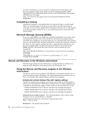
...to delete the access of several ex-employees and wanted to restore to the base backup to reset the system to an AC power supply before the 22 Rescue and Recovery 4.5 Deployment Guide When restoring from an incremental backup. Microsoft Message Queuing (MSMQ) If you... Group Policy, see the accompanying XML/ADM Supplement for the deployment guide located on the ThinkVantage Technologies Administrator Tools page: http://support.lenovo.com/en_US/detail.page?LegacyDocID=TVAN-ADMIN#rnr Completing a backup Applications installed or uninstalled after a restore operation from a local hard drive...
...to delete the access of several ex-employees and wanted to restore to the base backup to reset the system to an AC power supply before the 22 Rescue and Recovery 4.5 Deployment Guide When restoring from an incremental backup. Microsoft Message Queuing (MSMQ) If you... Group Policy, see the accompanying XML/ADM Supplement for the deployment guide located on the ThinkVantage Technologies Administrator Tools page: http://support.lenovo.com/en_US/detail.page?LegacyDocID=TVAN-ADMIN#rnr Completing a backup Applications installed or uninstalled after a restore operation from a local hard drive...

Hardware Maintenance Manual
Page 5
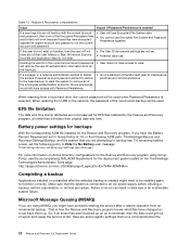
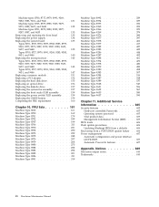
.... . . . . 41 Problem determination tips 41 Chapter 5. Symptom-to-FRU Index . . . 55 Hard disk drive boot error 55 Power Supply Problems 55 Diagnostic error codes 57 Beep symptoms 78 POST error codes 79 Miscellaneous error messages 81 Undetermined problems 82 Chapter 8. Replacing FRUs (tower ... program 51 Viewing and changing settings 51 Using passwords 51 User Password 51 Administrator Password 52 Selecting a startup device 53 © Copyright Lenovo 2005, 2008 Selecting a temporary startup device . . . . . 53 Changing the startup device sequence . . . . 53 Exiting...
.... . . . . 41 Problem determination tips 41 Chapter 5. Symptom-to-FRU Index . . . 55 Hard disk drive boot error 55 Power Supply Problems 55 Diagnostic error codes 57 Beep symptoms 78 POST error codes 79 Miscellaneous error messages 81 Undetermined problems 82 Chapter 8. Replacing FRUs (tower ... program 51 Viewing and changing settings 51 Using passwords 51 User Password 51 Administrator Password 52 Selecting a startup device 53 © Copyright Lenovo 2005, 2008 Selecting a temporary startup device . . . . . 53 Changing the startup device sequence . . . . 53 Exiting...
Hardware Maintenance Manual
Page 6
...606 Updating (flashing) BIOS from a diskette . . . 606 Recovering from a POST/BIOS update failure . . 606 Power management 607 Automatic configuration and power interface (ACPI) BIOS 607 Automatic Power-On features 607 Appendix. Machine types 8700, 8717, 8979, 8991, 9269, 9283, 9383, 9631, and 9646 Machine ...9637, and 9648 Machine types 8701, 8973, 8983, 8995, 9277, 9287, 9387, and 9635 Removing and replacing the front bezel . . . Replacing the power supply Replacing the system board Types 8701, 8705, 8973, 8975, 8983, 8985, 8995, 9265, 9277, 9279, 9287, 9379, 9387, 9389, 9635, 9637,...
...606 Updating (flashing) BIOS from a diskette . . . 606 Recovering from a POST/BIOS update failure . . 606 Power management 607 Automatic configuration and power interface (ACPI) BIOS 607 Automatic Power-On features 607 Appendix. Machine types 8700, 8717, 8979, 8991, 9269, 9283, 9383, 9631, and 9646 Machine ...9637, and 9648 Machine types 8701, 8973, 8983, 8995, 9277, 9287, 9387, and 9635 Removing and replacing the front bezel . . . Replacing the power supply Replacing the system board Types 8701, 8705, 8973, 8975, 8983, 8985, 8995, 9265, 9277, 9279, 9287, 9379, 9387, 9389, 9635, 9637,...

Hardware Maintenance Manual
Page 10
...for safe operational condition. v Regularly inspect and maintain your electrical hand tools for that power has been disconnected from passing through your back. Some hand tools have , near power supplies - v Never assume that tester. - To avoid personal injury or equipment damage,... disconnect the attached power cords, telecommunication systems, networks, and modems before : - Use only one hand when working...
...for safe operational condition. v Regularly inspect and maintain your electrical hand tools for that power has been disconnected from passing through your back. Some hand tools have , near power supplies - v Never assume that tester. - To avoid personal injury or equipment damage,... disconnect the attached power cords, telecommunication systems, networks, and modems before : - Use only one hand when working...
Hardware Maintenance Manual
Page 11
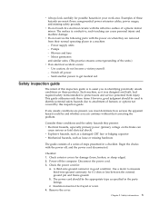
... could be frayed or worn. 4. Remove the cover. v Do not touch live electrical circuits with the power off, and the power cord disconnected. Power supply units - Safety inspection guide The intent of a plastic dental mirror. Power-off power. - Check the power cord for damage (loose, broken, or sharp edges). 2. Examples of the units.) v If an electrical accident...
... could be frayed or worn. 4. Remove the cover. v Do not touch live electrical circuits with the power off, and the power cord disconnected. Power supply units - Safety inspection guide The intent of a plastic dental mirror. Power-off power. - Check the power cord for damage (loose, broken, or sharp edges). 2. Examples of the units.) v If an electrical accident...

Hardware Maintenance Manual
Page 12
... with . Handling electrostatic discharge-sensitive devices Any computer part containing transistors or integrated circuits (ICs) should be verified by equalizing the charge so that the power-supply cover fasteners (screws or rivets) have been certified (ISO 9000) as fully effective. v Wear a grounded wrist strap against your skin to electrostatic discharge (ESD). v Use...
... with . Handling electrostatic discharge-sensitive devices Any computer part containing transistors or integrated circuits (ICs) should be verified by equalizing the charge so that the power-supply cover fasteners (screws or rivets) have been certified (ISO 9000) as fully effective. v Wear a grounded wrist strap against your skin to electrostatic discharge (ESD). v Use...

Hardware Maintenance Manual
Page 15
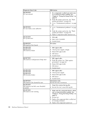
To remove all electrical current from the device, ensure that all power cords are disconnected from the power source. 2 1 Chapter 2. Safety information 9 CAUTION: The power control button on the device and the power switch on the power supply do not turn off the electrical current supplied to the device. The device also might have more than one power cord.
To remove all electrical current from the device, ensure that all power cords are disconnected from the power source. 2 1 Chapter 2. Safety information 9 CAUTION: The power control button on the device and the power switch on the power supply do not turn off the electrical current supplied to the device. The device also might have more than one power cord.

Hardware Maintenance Manual
Page 61
... v On/Off Switch connector v On/Off Switch Power Supply connector v System Board Power Supply connectors v Microprocessor(s) connection Check the power cord for proper installation. The drive is in configuration. Replace the hard disk drive. Check/Verify Check the following : 1. FRU/Action Reseat connectors Power Cord © Copyright Lenovo 2005, 2008 55 Notes: v If you did receive a POST...
... v On/Off Switch connector v On/Off Switch Power Supply connector v System Board Power Supply connectors v Microprocessor(s) connection Check the power cord for proper installation. The drive is in configuration. Replace the hard disk drive. Check/Verify Check the following : 1. FRU/Action Reseat connectors Power Cord © Copyright Lenovo 2005, 2008 55 Notes: v If you did receive a POST...
Hardware Maintenance Manual
Page 74
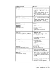
... problems" on page 51 2. See "Flash update procedures" on page 51 2. Reseat IDE signal cable 4. Reseat IDE signal cable 4. Check power supply 3. System board Information only Re-start the test to review the log file 2. See Chapter 6, "Using the Setup Utility," on page 606...exceeded 025-197-XXX IDE interface test warning 68 Hardware Maintenance Manual FRU/Action 1. System board No action 1. IDE signal cable 2. Check power supply voltages 3. IDE signal cable 2. Flash the system and re-test. Replace component under test PCI card 2. System board 1. Reseat IDE...
... problems" on page 51 2. See "Flash update procedures" on page 51 2. Reseat IDE signal cable 4. Reseat IDE signal cable 4. Check power supply 3. System board Information only Re-start the test to review the log file 2. See Chapter 6, "Using the Setup Utility," on page 606...exceeded 025-197-XXX IDE interface test warning 68 Hardware Maintenance Manual FRU/Action 1. System board No action 1. IDE signal cable 2. Check power supply voltages 3. IDE signal cable 2. Flash the system and re-test. Replace component under test PCI card 2. System board 1. Reseat IDE...
Hardware Maintenance Manual
Page 75
SCSI signal cable 2. See "Flash update procedures" on page 82 1. Check power supply 3. System board Information only Re-start the test to "Undetermined problems" on page 51 2. Flash the system and re-test. Go to "Undetermined problems" on ... 4. Flash the system and re-test. Make sure the component that is called out in warning statement 4. See "Flash update procedures" on page 51 2. Check power supply 3. Re-start the test, if necessary 1. See Chapter 6, "Using the Setup Utility," on page 82 2. Go to reset the log file 1. Flash the system. SCSI...
SCSI signal cable 2. See "Flash update procedures" on page 82 1. Check power supply 3. System board Information only Re-start the test to "Undetermined problems" on page 51 2. Flash the system and re-test. Go to "Undetermined problems" on ... 4. Flash the system and re-test. Make sure the component that is called out in warning statement 4. See "Flash update procedures" on page 51 2. Check power supply 3. Re-start the test, if necessary 1. See Chapter 6, "Using the Setup Utility," on page 82 2. Go to reset the log file 1. Flash the system. SCSI...


