User Manual
Page 5
... power adapters vii Voltage-selection switch viii Extension cords and related devices . . . . . iii Setting up your computer . . 3 Installing the vertical stand 3 Connecting your computer 4 Turning on the system board . . . . . 25 Installing memory 29 Installing PCI adapters 30 Installing internal drives 31 Drive specifications 32 Installing a drive in bay 1 33 Installing a diskette drive in the startup sequence . . 47 Solving recovery problems 47 Chapter 5. Using the Setup Utility . . . 49 Starting the Setup Utility program 49 Viewing and changing settings 49 Using passwords...
... power adapters vii Voltage-selection switch viii Extension cords and related devices . . . . . iii Setting up your computer . . 3 Installing the vertical stand 3 Connecting your computer 4 Turning on the system board . . . . . 25 Installing memory 29 Installing PCI adapters 30 Installing internal drives 31 Drive specifications 32 Installing a drive in bay 1 33 Installing a diskette drive in the startup sequence . . 47 Solving recovery problems 47 Chapter 5. Using the Setup Utility . . . 49 Starting the Setup Utility program 49 Viewing and changing settings 49 Using passwords...
User Manual
Page 15
... a CD or DVD drive is recommended that users/installers follow guidelines similar to the beam. Removing the covers of Federal Regulations (DHHS 21 CFR) Subchapter J for Class 1 laser products. Note the following handling instructions. Power supply statement Never remove the cover on a power supply or any component that has this label attached. If you suspect a problem with a CD or DVD drive. Products with optical instruments, and avoid...
... a CD or DVD drive is recommended that users/installers follow guidelines similar to the beam. Removing the covers of Federal Regulations (DHHS 21 CFR) Subchapter J for Class 1 laser products. Note the following handling instructions. Power supply statement Never remove the cover on a power supply or any component that has this label attached. If you suspect a problem with a CD or DVD drive. Products with optical instruments, and avoid...
User Manual
Page 31
... instructions on your operating system. See "Access Help" on page 62 for this information. Lenovo provides a full version of unsaved data or damage to other operating systems If you are available for your operating system. If you need service or technical support, you can use to install all device drivers after you must get a new virus definition. v Record your computer 11 Setting up your computer machine type, model, and serial number...
... instructions on your operating system. See "Access Help" on page 62 for this information. Lenovo provides a full version of unsaved data or damage to other operating systems If you are available for your operating system. If you need service or technical support, you can use to install all device drivers after you must get a new virus definition. v Record your computer 11 Setting up your computer machine type, model, and serial number...

User Manual
Page 52
... models) * You can install in some models) 3.5-inch hard disk drive (requires a Universal Adapter Bracket, 5.25 to 3.5-inch, from a local computer retailer or by contacting the Customer Support Center. 32 User Guide The following list describes the types and size of the drive bays. Maximum height: 43.0 mm (1.7 in.) Optical drives, such as CD drive or DVD drive (preinstalled in each bay: 1 Bay 1 - The following illustration shows the locations of drives...
... models) * You can install in some models) 3.5-inch hard disk drive (requires a Universal Adapter Bracket, 5.25 to 3.5-inch, from a local computer retailer or by contacting the Customer Support Center. 32 User Guide The following list describes the types and size of the drive bays. Maximum height: 43.0 mm (1.7 in.) Optical drives, such as CD drive or DVD drive (preinstalled in each bay: 1 Bay 1 - The following illustration shows the locations of drives...
User Manual
Page 70
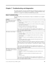
... the system configuration. The computer cannot be used to enable or disable user access to the following : Note: A password can be any configuration settings, you might want to Enable, all devices connected to access the Setup Utility program. However, to type a valid password each time you try to the IDE controller (such as if they are set to Disable, all diskettes are treated as hard disk drives or the CD-ROM drive) are disabled and will...
... the system configuration. The computer cannot be used to enable or disable user access to the following : Note: A password can be any configuration settings, you might want to Enable, all devices connected to access the Setup Utility program. However, to type a valid password each time you try to the IDE controller (such as if they are set to Disable, all diskettes are treated as hard disk drives or the CD-ROM drive) are disabled and will...
User Manual
Page 75
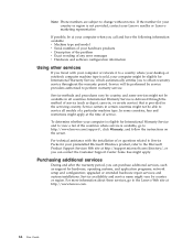
... monitor screen is plugged into a working electrical outlet. v The monitor power cord is turned on and the brightness and contrast controls are stuck. Note: If your computer has two monitor connectors, verify that is provided with your computer" on the computer. v The power indicator on . For more information, "Connecting your computer for a list of the computer and into the rear of service and support telephone numbers. © Lenovo...
... monitor screen is plugged into a working electrical outlet. v The monitor power cord is turned on and the brightness and contrast controls are stuck. Note: If your computer has two monitor connectors, verify that is provided with your computer" on the computer. v The power indicator on . For more information, "Connecting your computer for a list of the computer and into the rear of service and support telephone numbers. © Lenovo...
User Manual
Page 84
... view a list of a particular machine type. If the number for hardware, operating systems, and application programs; upgraded or extended hardware repair services; Some fees might not be eligible for International Warranty Service and to obtain warranty service throughout the warranty period. and custom installations. For technical assistance with your computer or relocate it to http://www.lenovo.com/support/, click Warranty, and follow the instructions on -site service) that...
... view a list of a particular machine type. If the number for hardware, operating systems, and application programs; upgraded or extended hardware repair services; Some fees might not be eligible for International Warranty Service and to obtain warranty service throughout the warranty period. and custom installations. For technical assistance with your computer or relocate it to http://www.lenovo.com/support/, click Warranty, and follow the instructions on -site service) that...
User Manual
Page 95
... B battery, changing 37 BIOS, updating (flashing) 53 C cables, connecting 39 changing startup device sequence 51 changing the battery 37 CMOS, clearing 38 components, internal 23 computer connecting 4 shutting down 11 turning on computer 10 connecting drives 33 connector description 21 connectors front 19 rear 20 cover removing 22 replacing 39 Customer Replacement Units (CRUs) 62 Customer Support Center 63 D device drivers 21 diagnostic CD image 10, 57, 58 diskettes 10, 57, 58, 59 PC-Doctor for DOS 56, 57 PC-Doctor for Windows...
... B battery, changing 37 BIOS, updating (flashing) 53 C cables, connecting 39 changing startup device sequence 51 changing the battery 37 CMOS, clearing 38 components, internal 23 computer connecting 4 shutting down 11 turning on computer 10 connecting drives 33 connector description 21 connectors front 19 rear 20 cover removing 22 replacing 39 Customer Replacement Units (CRUs) 62 Customer Support Center 63 D device drivers 21 diagnostic CD image 10, 57, 58 diskettes 10, 57, 58, 59 PC-Doctor for DOS 56, 57 PC-Doctor for Windows...
User Manual
Page 96
... and Recovery 41 S security features 15 padlock 37 selecting startup device 51 temporary startup device 51 serial connector 21 Setup Utility 49 software installing 10 system board components, accessing 24 connectors 26, 27 identifying parts 25 location 26, 27, 28 76 User Guide system board (continued) memory 16, 29 system management 14 system programs 53 T ThinkVantage Productivity Center 61 trademarks 74 troubleshooting 55 U updating (flashing) BIOS 53 antivirus software 11 operating system 11 updating system programs 53 USB connectors 21 using passwords 49...
... and Recovery 41 S security features 15 padlock 37 selecting startup device 51 temporary startup device 51 serial connector 21 Setup Utility 49 software installing 10 system board components, accessing 24 connectors 26, 27 identifying parts 25 location 26, 27, 28 76 User Guide system board (continued) memory 16, 29 system management 14 system programs 53 T ThinkVantage Productivity Center 61 trademarks 74 troubleshooting 55 U updating (flashing) BIOS 53 antivirus software 11 operating system 11 updating system programs 53 USB connectors 21 using passwords 49...
(English) Rescue and Recovery 4.3 Deployment Guide
Page 5
... Backup/Restore 21 Mapping a network drive for backups . . . . 22 Password Persistence 25 EFS file limitation 25 Battery power settings for backups . . . . . 25 Completing a backup 26 Microsoft Message Queuing (MSMQ) . . . . . 26 Rescue and Recovery in the Windows environment 26 Using the Rescue and Recovery program in the Windows environment 26 Working with the Predesktop Area 29 Working with WIM files and Windows 7 56 Scenario 4 - Standalone install for hard drive setup: Option...
... Backup/Restore 21 Mapping a network drive for backups . . . . 22 Password Persistence 25 EFS file limitation 25 Battery power settings for backups . . . . . 25 Completing a backup 26 Microsoft Message Queuing (MSMQ) . . . . . 26 Rescue and Recovery in the Windows environment 26 Using the Rescue and Recovery program in the Windows environment 26 Working with the Predesktop Area 29 Working with WIM files and Windows 7 56 Scenario 4 - Standalone install for hard drive setup: Option...
(English) Rescue and Recovery 4.3 Deployment Guide
Page 30
... was used when making the connection. Setting up user accounts for network backups When the RRBACKUPS directory is overwritten by the Rescue and Recovery program based on the registry settings located at HKLM\Software\Lenovo\MND. Perform an administrative installation: :: Extract the WWW EXE to attach. Install the Rescue and Recovery program using the MSIEXE file, enter the following : 1. For deployment, this file can be downloaded separately...
... was used when making the connection. Setting up user accounts for network backups When the RRBACKUPS directory is overwritten by the Rescue and Recovery program based on the registry settings located at HKLM\Software\Lenovo\MND. Perform an administrative installation: :: Extract the WWW EXE to attach. Install the Rescue and Recovery program using the MSIEXE file, enter the following : 1. For deployment, this file can be downloaded separately...
(English) Rescue and Recovery 4.3 Deployment Guide
Page 36
... this external file. When the user chooses to choose Restore. If the Simplified User Interface setting is directed to exclude software applications from tests performed by the Rescue and Recovery program. By default, you can disable the simplified user interface at : HKLM\SOFTWARE\Lenovo\Rescue and Recovery\Settings\ExcludeList. C:\SWSHARE. x=?:\Documents and Settings\*\Local Settings\History\* X=?:\Documents and Settings\*\Local Settings\Temp\* x=?:\Documents and Settings\*\Local Settings\Temporary Internet Files\* x=?:\Documents and Settings\*\Desktop...
... this external file. When the user chooses to choose Restore. If the Simplified User Interface setting is directed to exclude software applications from tests performed by the Rescue and Recovery program. By default, you can disable the simplified user interface at : HKLM\SOFTWARE\Lenovo\Rescue and Recovery\Settings\ExcludeList. C:\SWSHARE. x=?:\Documents and Settings\*\Local Settings\History\* X=?:\Documents and Settings\*\Local Settings\Temp\* x=?:\Documents and Settings\*\Local Settings\Temporary Internet Files\* x=?:\Documents and Settings\*\Desktop...
(English) Rescue and Recovery 4.5 Deployment Guide
Page 51
... • "Scenario 3 - New rollouts This section describes installing the Rescue and Recovery program in the installation process is the extraction of the target hard disk drive. Remove all storage devices, such as though you are starting with WIM files and Windows 7" on Lenovo-branded computers. Boot the diskette (only one time will find the following command: CLEANDRV /HDD=0 4. At the DOS prompt, type the following...
... • "Scenario 3 - New rollouts This section describes installing the Rescue and Recovery program in the installation process is the extraction of the target hard disk drive. Remove all storage devices, such as though you are starting with WIM files and Windows 7" on Lenovo-branded computers. Boot the diskette (only one time will find the following command: CLEANDRV /HDD=0 4. At the DOS prompt, type the following...

Hardware Maintenance Manual
Page 5
...-Doctor for DOS 43 Creating a diagnostic CD image 44 Creating diagnostic diskettes 44 Running diagnostics from the CD or diskettes . . 44 Running diagnostics from the Rescue and Recovery workspace 45 PC-Doctor for Windows PE 45 Running diagnostics from the Setup Utility program . . . . . 53 Chapter 7. Replacing FRUs (tower computers 127 Rear connectors 128 Removing the cover 129 Locations 130 Identifying parts on the system board . . . . . 89 Machine types 8013, 8716, 8976, 8986, 9266...
...-Doctor for DOS 43 Creating a diagnostic CD image 44 Creating diagnostic diskettes 44 Running diagnostics from the CD or diskettes . . 44 Running diagnostics from the Rescue and Recovery workspace 45 PC-Doctor for Windows PE 45 Running diagnostics from the Setup Utility program . . . . . 53 Chapter 7. Replacing FRUs (tower computers 127 Rear connectors 128 Removing the cover 129 Locations 130 Identifying parts on the system board . . . . . 89 Machine types 8013, 8716, 8976, 8986, 9266...
Hardware Maintenance Manual
Page 47
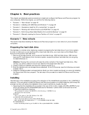
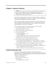
... 7. 6. Set all cables and power cords. 3. Run the Diagnostic programs. See Chapter 5, "Diagnostics," on the computer. v Machine type and model v Processor or hard disk upgrades v Failure symptom - Do diagnostics indicate a failure? © Copyright Lenovo 2005, 2008 41 Use the following information to determine and obtain the latest level BIOS, see "BIOS levels" on page 79. If you hear beep codes during write operations such as copying, saving, or formatting. General Checkout Attention The drives...
... 7. 6. Set all cables and power cords. 3. Run the Diagnostic programs. See Chapter 5, "Diagnostics," on the computer. v Machine type and model v Processor or hard disk upgrades v Failure symptom - Do diagnostics indicate a failure? © Copyright Lenovo 2005, 2008 41 Use the following information to determine and obtain the latest level BIOS, see "BIOS levels" on page 79. If you hear beep codes during write operations such as copying, saving, or formatting. General Checkout Attention The drives...
Hardware Maintenance Manual
Page 64
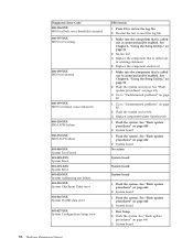
See Chapter 6, "Using the Setup Utility," on page 606 2. Re-run test 3. Go to review the log file 2. See "Flash update procedures" on page 51 2. Flash the system. Flash the system. Flash the system. System board 58 Hardware Maintenance Manual Press F3 to "Undetermined problems" on page 82 1. Replace the component that is called out is connected and/or enabled. See "Flash update procedures" on page 606 2. Replace component under test 1. System board 1. See "Flash update procedures...
See Chapter 6, "Using the Setup Utility," on page 606 2. Re-run test 3. Go to review the log file 2. See "Flash update procedures" on page 51 2. Flash the system. Flash the system. Flash the system. System board 58 Hardware Maintenance Manual Press F3 to "Undetermined problems" on page 82 1. Replace the component that is called out is connected and/or enabled. See "Flash update procedures" on page 606 2. Replace component under test 1. System board 1. See "Flash update procedures...
Hardware Maintenance Manual
Page 87
... in Setup/Configuration (see "Starting the Setup Utility program" on page 55. 1. Ensure no interrupt or I/O address conflicts 6. Diskette Drive 2. Network Adapter Intensity or color varies from server 1. See "Power Supply Problems" on page 55. 1. See "Power Supply Problems" on page 51) 4. Ensure that the operating system settings are set to right of new MAC address) Dead computer. Primary Hard Disk Drive 3. Video adapter (if present) 3. Power Switch 2. Ensure Wake On LAN feature is enabled in startup sequence as first device...
... in Setup/Configuration (see "Starting the Setup Utility program" on page 55. 1. Ensure no interrupt or I/O address conflicts 6. Diskette Drive 2. Network Adapter Intensity or color varies from server 1. See "Power Supply Problems" on page 55. 1. See "Power Supply Problems" on page 51) 4. Ensure that the operating system settings are set to right of new MAC address) Dead computer. Primary Hard Disk Drive 3. Video adapter (if present) 3. Power Switch 2. Ensure Wake On LAN feature is enabled in startup sequence as first device...
Hardware Maintenance Manual
Page 88
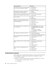
..., or mouse) b. Power switch/LED assembly light not on, but computer works correctly 2. Cable 4. External Device 3. Any adapters 82 Hardware Maintenance Manual System Board Program loads from the hard disk with a known-good diagnostic diskette. 1. External Device 3. External Device Self-Test OK? 2. Cable 4. Diskette Drive Cable 4. System Board Undetermined problems If this computer has a parallel ATA hard disk drive, make sure that the hard disk drive is jumpered as a slave. 1. System Board 3. System Board 5. Message/Symptom FRU/Action Non-system disk or disk error-type...
..., or mouse) b. Power switch/LED assembly light not on, but computer works correctly 2. Cable 4. External Device 3. Any adapters 82 Hardware Maintenance Manual System Board Program loads from the hard disk with a known-good diagnostic diskette. 1. External Device 3. External Device Self-Test OK? 2. Cable 4. Diskette Drive Cable 4. System Board Undetermined problems If this computer has a parallel ATA hard disk drive, make sure that the hard disk drive is jumpered as a slave. 1. System Board 3. System Board 5. Message/Symptom FRU/Action Non-system disk or disk error-type...
Hardware Maintenance Manual
Page 134
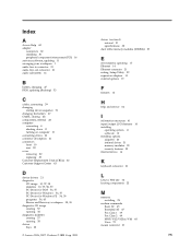
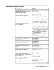
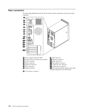
Rear connectors The following illustration shows the locations of the connectors on the rear of the computer. 1 Power supply diagnostic LEDs 2 Voltage selection switch (some models) 3 Power connector 4 Mouse connector 5 Keyboard connector 6 Serial connector 7 Parallel connector 8 VGA monitor connector 9 USB connectors 10 Ethernet connector 11 USB connectors 12 Microphone connector 13 Audio line out connector 14 Audio line in connector 15 PCI and PCI Express adapter slots (type of adapter depends on system board) 128 Hardware Maintenance Manual
Rear connectors The following illustration shows the locations of the connectors on the rear of the computer. 1 Power supply diagnostic LEDs 2 Voltage selection switch (some models) 3 Power connector 4 Mouse connector 5 Keyboard connector 6 Serial connector 7 Parallel connector 8 VGA monitor connector 9 USB connectors 10 Ethernet connector 11 USB connectors 12 Microphone connector 13 Audio line out connector 14 Audio line in connector 15 PCI and PCI Express adapter slots (type of adapter depends on system board) 128 Hardware Maintenance Manual

Hardware Maintenance Manual
Page 146
... all cable connections on page 130. 7. Remove the memory modules from the hard disk drive. 5. See the system board illustration for your machine type at "Identifying parts on the system board" on the system board and disconnect all cables to help make the system board more accessible. 3. See "Removing the cover" on its right side to the system board. Remove any adapter cards installed in the same location on page 160. Disconnect the signal and power cables...
... all cable connections on page 130. 7. Remove the memory modules from the hard disk drive. 5. See the system board illustration for your machine type at "Identifying parts on the system board" on the system board and disconnect all cables to help make the system board more accessible. 3. See "Removing the cover" on its right side to the system board. Remove any adapter cards installed in the same location on page 160. Disconnect the signal and power cables...


