User Manual
Page 24
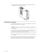
4. Connecting your computer Use the following information when connecting your computer cables and connector panel have all of the connector. Carefully, position the computer with the air vents facing upward so that the computer sits on the back of the ...
4. Connecting your computer Use the following information when connecting your computer cables and connector panel have all of the connector. Carefully, position the computer with the air vents facing upward so that the computer sits on the back of the ...

User Manual
Page 30
... refund. See "Access Help" on page 62 for instructions on how to the Access Help online help and information by telephone through the Windows Control Panel. Diagnostic programs are used to run diagnostics if the Rescue and Recovery workspace becomes inaccessible. Turning on power Turn on the monitor and other external...
... refund. See "Access Help" on page 62 for instructions on how to the Access Help online help and information by telephone through the Windows Control Panel. Diagnostic programs are used to run diagnostics if the Rescue and Recovery workspace becomes inaccessible. Turning on power Turn on the monitor and other external...
User Manual
Page 34
... the system board (some models) Audio subsystem v High-definition ADI 1986 Audio Codec v Microphone and headphone connectors on the front panel v Line in, line out, and microphone connectors on the rear panel Connectivity v 10/100 Mbps integrated Ethernet controller (some models) v 10/100/1000 Mbps integrated Ethernet controller (some models) v Soft modem...
... the system board (some models) Audio subsystem v High-definition ADI 1986 Audio Codec v Microphone and headphone connectors on the front panel v Line in, line out, and microphone connectors on the rear panel Connectivity v 10/100 Mbps integrated Ethernet controller (some models) v 10/100/1000 Mbps integrated Ethernet controller (some models) v Soft modem...
User Manual
Page 35
...Microsoft Windows XP Home v Microsoft Windows XP Professional v Microsoft Windows Vista™ Chapter 3. v Six USB connectors (two on front panel and four on rear panel) v Standard mouse connector v Standard keyboard connector v Ethernet connector v VGA monitor connector v Three audio connectors (line in, line ...out, and microphone) on rear panel v Two audio connectors (microphone and headphone) on front panel Expansion v Three drive bays v Two low-profile 32-bit PCI adapter connectors v One low-profile PCI ...
...Microsoft Windows XP Home v Microsoft Windows XP Professional v Microsoft Windows Vista™ Chapter 3. v Six USB connectors (two on front panel and four on rear panel) v Standard mouse connector v Standard keyboard connector v Ethernet connector v VGA monitor connector v Three audio connectors (line in, line ...out, and microphone) on rear panel v Two audio connectors (microphone and headphone) on front panel Expansion v Three drive bays v Two low-profile 32-bit PCI adapter connectors v One low-profile PCI ...

User Manual
Page 46
The following illustration shows the locations of parts on the system board for some computer models. 1 Microprocessor fan connector 12 Front panel connector 2 Microprocessor and heat sink 13 SATA IDE connectors (2) 3 Memory connector 1 14 Front USB connectors (2) 4 Memory connector 2 15 Serial (COM) connector 5 Clear CMOS/Recovery jumper ...
The following illustration shows the locations of parts on the system board for some computer models. 1 Microprocessor fan connector 12 Front panel connector 2 Microprocessor and heat sink 13 SATA IDE connectors (2) 3 Memory connector 1 14 Front USB connectors (2) 4 Memory connector 2 15 Serial (COM) connector 5 Clear CMOS/Recovery jumper ...

User Manual
Page 47
... adapter connector 7 IDE connector 18 Battery 8 SATA IDE connectors (2) 19 PCI Express x16 graphics adapter connector 9 Power fan connector 20 System fan connector 10 Front panel connector 21 12v power connector 11 Clear CMOS/Recovery jumper Chapter 3. Installing options 27
... adapter connector 7 IDE connector 18 Battery 8 SATA IDE connectors (2) 19 PCI Express x16 graphics adapter connector 9 Power fan connector 20 System fan connector 10 Front panel connector 21 12v power connector 11 Clear CMOS/Recovery jumper Chapter 3. Installing options 27

User Manual
Page 48
... 1 4 Memory connector 2 5 Diskette drive connector 6 Power connector 7 IDE connector 1 8 IDE connector 2 9 Power fan connector 10 SATA IDE connectors (2) 11 Clear CMOS/Recovery jumper 12 Front panel connector 13 Front USB connectors (2) 14 Front audio connector 15 CD-IN connector 16 PCI adapter connectors 17 PCI Express x1 adapter connector 18 Battery...
... 1 4 Memory connector 2 5 Diskette drive connector 6 Power connector 7 IDE connector 1 8 IDE connector 2 9 Power fan connector 10 SATA IDE connectors (2) 11 Clear CMOS/Recovery jumper 12 Front panel connector 13 Front USB connectors (2) 14 Front audio connector 15 CD-IN connector 16 PCI adapter connectors 17 PCI Express x1 adapter connector 18 Battery...

User Manual
Page 52
... 1 - The following factory-installed drives: v An optical drive in bay 1 (some models) Any bay that does not have a drive installed has a static shield and bay panel installed.
... 1 - The following factory-installed drives: v An optical drive in bay 1 (some models) Any bay that does not have a drive installed has a static shield and bay panel installed.

User Manual
Page 53
Access the system board. If you are installing a drive with accessible media, such as an optical drive, remove the plastic panel in bay 1, do the following procedures for your computer or with the new drive. 2. See "Connecting drives." See "Identifying parts on the system ... Universal Adapter Bracket, if the retainer bracket is not available, install the screws to 3.5-inch. Locate the two-connector signal cable that secure the panel on the system board. Installing a drive in bay 1 To install an optical drive or an additional hard disk drive in the bezel by contacting...
Access the system board. If you are installing a drive with accessible media, such as an optical drive, remove the plastic panel in bay 1, do the following procedures for your computer or with the new drive. 2. See "Connecting drives." See "Identifying parts on the system ... Universal Adapter Bracket, if the retainer bracket is not available, install the screws to 3.5-inch. Locate the two-connector signal cable that secure the panel on the system board. Installing a drive in bay 1 To install an optical drive or an additional hard disk drive in the bezel by contacting...

User Manual
Page 54
...SATA connector on page 22. 2. What to do the following: 1. See "Removing the cover" on the system board. Access the system board. Remove the plastic panel in bay 3, do next: v To work with the new drive. 2. See "Identifying parts on the system board" on page 24. 3. Installing a diskette ...the bezel by using a flat-blade screwdriver to any available SATA connector. 1. Remove the computer cover. Locate the signal cable that secure the panel on the inside of the extra five-wire power connectors and connect it to "Replacing the cover and connecting the cables" on the system ...
...SATA connector on page 22. 2. What to do the following: 1. See "Removing the cover" on the system board. Access the system board. Remove the plastic panel in bay 3, do next: v To work with the new drive. 2. See "Identifying parts on the system board" on page 24. 3. Installing a diskette ...the bezel by using a flat-blade screwdriver to any available SATA connector. 1. Remove the computer cover. Locate the signal cable that secure the panel on the inside of the extra five-wire power connectors and connect it to "Replacing the cover and connecting the cables" on the system ...

User Manual
Page 66
...The latest device drivers for a SETUP.EXE file. v If the device subfolder contains a file with the partition that are installed in the Windows Control Panel) to reinstall the device driver. v In the device subfolder, look for the device. 2. When you can recover or install device drivers, your operating...device driver: v In the device subfolder, look for factory-installed devices also are located on the World Wide Web at http://www.lenovo.com/think/support/. If an error message appears during the repair operation and the repair operation cannot be able to display the directory ...
...The latest device drivers for a SETUP.EXE file. v If the device subfolder contains a file with the partition that are installed in the Windows Control Panel) to reinstall the device driver. v In the device subfolder, look for the device. 2. When you can recover or install device drivers, your operating...device driver: v In the device subfolder, look for factory-installed devices also are located on the World Wide Web at http://www.lenovo.com/think/support/. If an error message appears during the repair operation and the repair operation cannot be able to display the directory ...

User Manual
Page 82
...the Search tab to find a wide variety of sources available to help you will find a particular word or phrase. www.lenovo.com The Lenovo Web site (www.lenovo.com) provides an extensive amount of Limited Warranty. You can also: v Shop for desktop and notebook computers, monitors, ... the ThinkVantage Productivity Center program, open the Start menu from the Contents or Index tab, or use the left panel to -date information for your computer. From the www.lenovo.com Web site, you . v Access the online manuals for your personal preference, protecting data, expanding and upgrading...
...the Search tab to find a wide variety of sources available to help you will find a particular word or phrase. www.lenovo.com The Lenovo Web site (www.lenovo.com) provides an extensive amount of Limited Warranty. You can also: v Shop for desktop and notebook computers, monitors, ... the ThinkVantage Productivity Center program, open the Start menu from the Contents or Index tab, or use the left panel to -date information for your computer. From the www.lenovo.com Web site, you . v Access the online manuals for your personal preference, protecting data, expanding and upgrading...
(English) Rescue and Recovery 4.3 Deployment Guide
Page 17
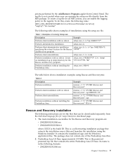
... Example Perform silent installation with no reboot. The log file is in temp directory for all MSI actions, you can be downloaded separately from Control Panel. Perform silent uninstallation. Create an installation log in the following table shows examples of installations using Rescue and Recovery.msi: Table 2. To do this, create...
... Example Perform silent installation with no reboot. The log file is in temp directory for all MSI actions, you can be downloaded separately from Control Panel. Perform silent uninstallation. Create an installation log in the following table shows examples of installations using Rescue and Recovery.msi: Table 2. To do this, create...
(English) Rescue and Recovery 4.3 Deployment Guide
Page 22
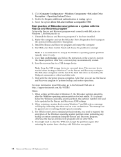
... system partition when performing any backup or restore operations using Windows 7 and BitLocker, a message will be after restoring the system from Control Panel and choose the partition to encrypt the Windows operating system partition (usually drive C) only. 5. Install the Rescue and Recovery program and restart...a compatible TPM. The message can use the BitLocker Drive Preparation Tool to perform backup and restore operations. For OEM or non-Lenovo standard preload systems, you can be ignored and everything should be lost if the hard disk drive is needed when booting to a...
... system partition when performing any backup or restore operations using Windows 7 and BitLocker, a message will be after restoring the system from Control Panel and choose the partition to encrypt the Windows operating system partition (usually drive C) only. 5. Install the Rescue and Recovery program and restart...a compatible TPM. The message can use the BitLocker Drive Preparation Tool to perform backup and restore operations. For OEM or non-Lenovo standard preload systems, you can be ignored and everything should be lost if the hard disk drive is needed when booting to a...

(English) Rescue and Recovery 4.3 Deployment Guide
Page 37
...MAINBK.BMP Modify environment background. The \minint subdirectory does not exist on the ThinkVantage Technologies Administrator Tools page: http://www.lenovo.com/support/site.wss/document.do?lndocid=TVANADMIN#rnr Working with the Predesktop Area To customize parts of the Rescue and ...Policy, see the accompanying XML/ADM Supplement for Windows Vista. Preboot environment: main GUI fonts, environment background, left and right panel entries and functions, HTML-based help system. RRUTIL.exe files and customization options File or Directory Customization options \MININT\SYSTEM32 WINBOM...
...MAINBK.BMP Modify environment background. The \minint subdirectory does not exist on the ThinkVantage Technologies Administrator Tools page: http://www.lenovo.com/support/site.wss/document.do?lndocid=TVANADMIN#rnr Working with the Predesktop Area To customize parts of the Rescue and ...Policy, see the accompanying XML/ADM Supplement for Windows Vista. Preboot environment: main GUI fonts, environment background, left and right panel entries and functions, HTML-based help system. RRUTIL.exe files and customization options File or Directory Customization options \MININT\SYSTEM32 WINBOM...

(English) Rescue and Recovery 4.3 Deployment Guide
Page 44
....EXE -p C:\temp Example 2 : Adding mass-storage controller drivers (such as SATA) to manually apply some configuration applications or settings as they are in the left panel of the user interface v The HTML-based help system for the character style that might not display all characters correctly, depending on your visual and...
....EXE -p C:\temp Example 2 : Adding mass-storage controller drivers (such as SATA) to manually apply some configuration applications or settings as they are in the left panel of the user interface v The HTML-based help system for the character style that might not display all characters correctly, depending on your visual and...

(English) Rescue and Recovery 4.3 Deployment Guide
Page 45
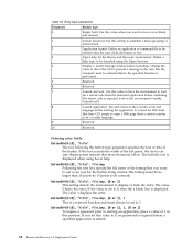
... the order by which the buttons are different, each button type: Chapter 3. The following table explains the type and behavior of a left-panel entry: [LeftMenu] button00=2, "Introduction", Introduction.bmp, 1, 1, 0, %tvtdrive%\Preboot\Opera\ENum3.exe, Table 17. Configurations 37 For information ...1. Button00=[0-8] This parameter determines the button type. Text can be defined. Changing the environment background The background of the right panel is a bitmap graphic and is an example of each entry has the same basic elements. Text can be added. 03-06...
... the order by which the buttons are different, each button type: Chapter 3. The following table explains the type and behavior of a left-panel entry: [LeftMenu] button00=2, "Introduction", Introduction.bmp, 1, 1, 0, %tvtdrive%\Preboot\Opera\ENum3.exe, Table 17. Configurations 37 For information ...1. Button00=[0-8] This parameter determines the button type. Text can be defined. Changing the environment background The background of the right panel is a bitmap graphic and is an example of each entry has the same basic elements. Text can be added. 03-06...
(English) Rescue and Recovery 4.3 Deployment Guide
Page 46
... browser. 4 Display a restart message window before launching. If you want to be no password is required before starting an application, place a value of the left panel, the text is displayed. Change the value to direct the GUI to present a message to the user that have CGI scripts to be restarted before...
... browser. 4 Display a restart message window before launching. If you want to be no password is required before starting an application, place a value of the left panel, the text is displayed. Change the value to direct the GUI to present a message to the user that have CGI scripts to be restarted before...
(English) Rescue and Recovery 4.3 Deployment Guide
Page 47
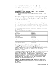
... Executable WIZRR.EXE WIZRR.EXE OPERA.EXE MAPDRV.EXE PCDR.CMD; Left-panel functions and executables Function Recover files Restore from the left panel. launches the PC Doctor application, and Lenovo-branded preinstallation models only DDIAGS.CMD Changing entries and functions in the left... -panel entries: Table 19. The same applications that you must remain type 0 (or header...
... Executable WIZRR.EXE WIZRR.EXE OPERA.EXE MAPDRV.EXE PCDR.CMD; Left-panel functions and executables Function Recover files Restore from the left panel. launches the PC Doctor application, and Lenovo-branded preinstallation models only DDIAGS.CMD Changing entries and functions in the left... -panel entries: Table 19. The same applications that you must remain type 0 (or header...

(English) Rescue and Recovery 4.3 Deployment Guide
Page 48
Depending on the changes that you have made to the left panel, you can change the information in . To change NoShowCk=0 to the Lenovo support site" Line09 = "*Troubleshoot problems using diagnostics" Line10 = "diagnose problems using Rescue and Recovery(TM)" Line05 = "*...Configure your system settings and passwords" Line06 = "your font design preferences. 40 Rescue and Recovery 4.3 Deployment Guide v Command1 Lenovo License Agreement HTML page. You can do the following settings are for the Title Bar Help functions on installation options. Line12 = "NOTICE:"...
Depending on the changes that you have made to the left panel, you can change the information in . To change NoShowCk=0 to the Lenovo support site" Line09 = "*Troubleshoot problems using diagnostics" Line10 = "diagnose problems using Rescue and Recovery(TM)" Line05 = "*...Configure your system settings and passwords" Line06 = "your font design preferences. 40 Rescue and Recovery 4.3 Deployment Guide v Command1 Lenovo License Agreement HTML page. You can do the following settings are for the Title Bar Help functions on installation options. Line12 = "NOTICE:"...


