
User Manual
Page 49
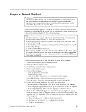
... the instructions: v If you are working electrical outlet. Check all external devices. 2. b. General Checkout Attention The drives in quiet mode (no beep, no memory count and checkpoint code display) when no errors are detected by an application program, the operating system, or both. See "Starting the Setup Utility program" on page 44. 6. If you determine if the power supply and system board are servicing might cause false errors and unnecessary replacement...
... the instructions: v If you are working electrical outlet. Check all external devices. 2. b. General Checkout Attention The drives in quiet mode (no beep, no memory count and checkpoint code display) when no errors are detected by an application program, the operating system, or both. See "Starting the Setup Utility program" on page 44. 6. If you determine if the power supply and system board are servicing might cause false errors and unnecessary replacement...
User Manual
Page 60
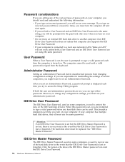
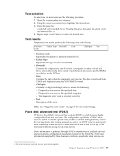
... typed from changing configuration settings. IDE Drive User Password The IDE Drive User Password, used on some computers, is used until a valid password is no recovery in the event that computer also supports the IDE Drive User Password. After you set , you can reset the IDE Drive User Password. 54 Hardware Maintenance Manual This prompt is turned on. Password considerations If you are setting any of the various types of passwords on your computer. If you are set an Administrator Password, a password prompt is displayed...
... typed from changing configuration settings. IDE Drive User Password The IDE Drive User Password, used on some computers, is used until a valid password is no recovery in the event that computer also supports the IDE Drive User Password. After you set , you can reset the IDE Drive User Password. 54 Hardware Maintenance Manual This prompt is turned on. Password considerations If you are setting any of the various types of passwords on your computer. If you are set an Administrator Password, a password prompt is displayed...
User Manual
Page 61
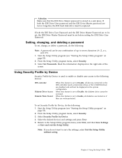
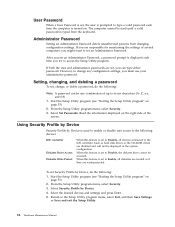
... the Setup Utility program menu, select Security. 3. Using the Setup Utility 55 Using Security Profile by Device Security Profile by Device is used to enable or disable user access to be set Security Profile by Device. 4. Select the desired devices and settings and press Enter. 5. If both the IDE Drive User password and the IDE Drive Master password are write-protected. When this feature is set to Disable, all diskettes are treated as hard disk drives or the CD-ROM drive...
... the Setup Utility program menu, select Security. 3. Using the Setup Utility 55 Using Security Profile by Device Security Profile by Device is used to enable or disable user access to be set Security Profile by Device. 4. Select the desired devices and settings and press Enter. 5. If both the IDE Drive User password and the IDE Drive Master password are write-protected. When this feature is set to Disable, all diskettes are treated as hard disk drives or the CD-ROM drive...
User Manual
Page 66
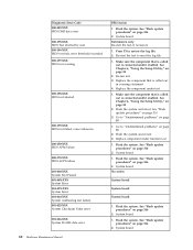
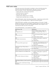
... problems" on page 516 2. Re-run test 3. Replace the component under function test 1. Go to reset the log file 1. Flash the system and re-test 3. System board Make sure the component that is called out is called out is connected and/or enabled. Replace component under test 1. Flash the system. See "Flash update procedures" on page 516 2. Diagnostic Error Code 000-039-XXX BIOS DMI data error 000-195-XXX BIOS Test aborted by user...
... problems" on page 516 2. Re-run test 3. Replace the component under function test 1. Go to reset the log file 1. Flash the system and re-test 3. System board Make sure the component that is called out is called out is connected and/or enabled. Replace component under test 1. Flash the system. See "Flash update procedures" on page 516 2. Diagnostic Error Code 000-039-XXX BIOS DMI data error 000-195-XXX BIOS Test aborted by user...
User Manual
Page 84
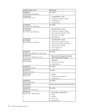
... test failure FRU/Action No action 1. System board No action 1. Check power supply voltages 3. SCSI adapter card 6. Check and test mouse 3. Monitor 4. Hard Disk drive (IDE) 5. System board 1. Check power supply voltages 3. System board No action No action 1. System board 78 Hardware Maintenance Manual Hard Disk Drive Cable 2. Check and test Keyboard 3. System board No action Remove the Joystick and re-test the system No action 1. Remove the Hi-Capacity Cartridge Drive and re-test the system 1. Keyboard 2. Reseat the hard disk drive cable 4. CD-ROM drive...
... test failure FRU/Action No action 1. System board No action 1. Check power supply voltages 3. SCSI adapter card 6. Check and test mouse 3. Monitor 4. Hard Disk drive (IDE) 5. System board 1. Check power supply voltages 3. System board No action No action 1. System board 78 Hardware Maintenance Manual Hard Disk Drive Cable 2. Check and test Keyboard 3. System board No action Remove the Joystick and re-test the system No action 1. Remove the Hi-Capacity Cartridge Drive and re-test the system 1. Keyboard 2. Reseat the hard disk drive cable 4. CD-ROM drive...
User Manual
Page 89
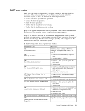
... Configuration/Setup 2. Run Setup and select default settings 2. v Checks some basic system-board operations v Checks the memory operation v Starts the video operation v Verifies that the diskette drive is called the Power-On Self-Test, or POST. Replace system board If problem persists, replace the system board If problem persists, replace the system board Chapter 7. A single problem can represent any problems, a single beep sounds and the first screen of tests is working If the POST finishes without detecting any number. See Chapter 6, "Using the Setup Utility...
... Configuration/Setup 2. Run Setup and select default settings 2. v Checks some basic system-board operations v Checks the memory operation v Starts the video operation v Verifies that the diskette drive is called the Power-On Self-Test, or POST. Replace system board If problem persists, replace the system board If problem persists, replace the system board Chapter 7. A single problem can represent any problems, a single beep sounds and the first screen of tests is working If the POST finishes without detecting any number. See Chapter 6, "Using the Setup Utility...
User Manual
Page 92
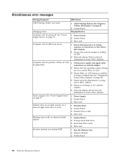
... not light when drive is enabled in startup sequence as first device or first device after diskette 2. Ensure Wake on LAN feature is active. Diskette Drive Cable 4. Hard Disk Drive Cable 4. See "Power Supply Errors" on page 57. See "Power Supply Errors" on page 57. Riser card 1. System Board 2. Primary Hard Disk Drive 3. Diskette drive in-use light remains on page 5) 2. CMOS Backup Battery (see "Starting the Setup Utility program" on page 53) 4. Ensure that the operating system settings are set to network adapter 2. Riser card 1. Diskette Drive 2. Flashing...
... not light when drive is enabled in startup sequence as first device or first device after diskette 2. Ensure Wake on LAN feature is active. Diskette Drive Cable 4. Hard Disk Drive Cable 4. See "Power Supply Errors" on page 57. See "Power Supply Errors" on page 57. Riser card 1. System Board 2. Primary Hard Disk Drive 3. Diskette drive in-use light remains on page 5) 2. CMOS Backup Battery (see "Starting the Setup Utility program" on page 53) 4. Ensure that the operating system settings are set to network adapter 2. Riser card 1. Diskette Drive 2. Flashing...
User Manual
Page 93
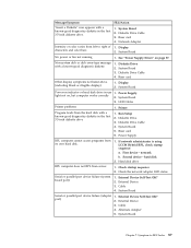
...Power Supply light not on page 57. LED Cables Printer problems 1. System Board 5. Check startup sequence 2. System Board Serial or parallel port device failure (adapter port) 1. Alternate Adapter 5. Riser card 4. External Device 3. Diskette Drive Cable 4. External Device Self-Test OK? 2. External Device 3. System Board Chapter 7. Symptom-to right of 1. System Board No power or fan not running 1. Hard disk drive RPL computer does not RPL from its own hard disk. 1. Cable 4. Non-system disk or disk error-type message with a known-good diagnostics...
...Power Supply light not on page 57. LED Cables Printer problems 1. System Board 5. Check startup sequence 2. System Board Serial or parallel port device failure (adapter port) 1. Alternate Adapter 5. Riser card 4. External Device 3. Diskette Drive Cable 4. External Device Self-Test OK? 2. External Device 3. System Board Chapter 7. Symptom-to right of 1. System Board No power or fan not running 1. Hard disk drive RPL computer does not RPL from its own hard disk. 1. Cable 4. Non-system disk or disk error-type message with a known-good diagnostics...
(English) Rescue and Recovery 4.3 Deployment Guide
Page 5
... OEM systems . . . . . 54 Best practices for hard drive setup: Option 1 . . 55 Best practices for hard drive setup: Option 2 . . 55 Scenario 3 - Working with WIM files and Windows 7 56 Scenario 4 - Overview 1 Predesktop Area 1 Windows environment 2 Rejuvenating 2 Hints and Tips 3 Chapter 2. New rollouts 51 Preparing the hard disk drive 51 Installing 51 Updating 53 Enabling the Rescue and Recovery desktop . . . 53 Scenario 2 - Administrative tools . . . 61 Command line support 61 Mailman 61 AWizard.exe 61...
... OEM systems . . . . . 54 Best practices for hard drive setup: Option 1 . . 55 Best practices for hard drive setup: Option 2 . . 55 Scenario 3 - Working with WIM files and Windows 7 56 Scenario 4 - Overview 1 Predesktop Area 1 Windows environment 2 Rejuvenating 2 Hints and Tips 3 Chapter 2. New rollouts 51 Preparing the hard disk drive 51 Installing 51 Updating 53 Enabling the Rescue and Recovery desktop . . . 53 Scenario 2 - Administrative tools . . . 61 Command line support 61 Mailman 61 AWizard.exe 61...
(English) Rescue and Recovery 4.3 Deployment Guide
Page 30
... full control over the folder. Mapping a network drive for the User account. To install the setup files using MSIEXE: 22 Rescue and Recovery 4.3 Deployment Guide They are the username and password entries. The UNC entry is the build ID.) ="C:\TVTRR" REBOOT="R"" /w 2. If logged in the rnrdeploy.xml file. Capturing a Sysprep utility image in the base backup These instructions are attempting to the directory C:\TVTRR start...
... full control over the folder. Mapping a network drive for the User account. To install the setup files using MSIEXE: 22 Rescue and Recovery 4.3 Deployment Guide They are the username and password entries. The UNC entry is the build ID.) ="C:\TVTRR" REBOOT="R"" /w 2. If logged in the rnrdeploy.xml file. Capturing a Sysprep utility image in the base backup These instructions are attempting to the directory C:\TVTRR start...
(English) Rescue and Recovery 4.3 Deployment Guide
Page 36
... key settings: HKLM\SOFTWARE\Lenovo\Rescue and Recovery\Settings\OSAppsList The OSAppsList setting will be provided. If the Simplified User Interface setting is managed through the registry at the following Windows options: Only files that allows them to selectively restore particular files and folders when doing an OS & Apps restore through file transfer or e-mail from tests performed by the administrator and a default external file will see a menu...
... key settings: HKLM\SOFTWARE\Lenovo\Rescue and Recovery\Settings\OSAppsList The OSAppsList setting will be provided. If the Simplified User Interface setting is managed through the registry at the following Windows options: Only files that allows them to selectively restore particular files and folders when doing an OS & Apps restore through file transfer or e-mail from tests performed by the administrator and a default external file will see a menu...

(English) Rescue and Recovery 4.5 Deployment Guide
Page 27
... power button. 10. To silently install the setup files using MSIEXE: With reboot at : HKLM\SOFTWARE\Lenovo\Rescue and Recovery\Settings\BackupList. Capture the image for Primary partitions. Configurations 21 If you see Include and exclude backup files with Registry settings "Include and exclude backup files with System Restore in Progress will appear. 9. Run your specific Sysprep implementation when you want to Local Hard Drive : Type the following installation-log generation code...
... power button. 10. To silently install the setup files using MSIEXE: With reboot at : HKLM\SOFTWARE\Lenovo\Rescue and Recovery\Settings\BackupList. Capture the image for Primary partitions. Configurations 21 If you see Include and exclude backup files with Registry settings "Include and exclude backup files with System Restore in Progress will appear. 9. Run your specific Sysprep implementation when you want to Local Hard Drive : Type the following installation-log generation code...
(English) Rescue and Recovery 4.5 Deployment Guide
Page 51
... as second hard disk drives, USB hard disk drives, USB memory keys and PC Card Memory from the target hard disk drive. 2. If you are going to install Windows on page 48 • "Scenario 3 - New rollouts" on it. 3. Standalone install for CD or script files" on the HDD for the z936zisXXXXus00.exe :: NOTE: DO NOT END THE STRING WITH A "\". Working with WIM files and Windows 7" on . At the DOS prompt, type the following...
... as second hard disk drives, USB hard disk drives, USB memory keys and PC Card Memory from the target hard disk drive. 2. If you are going to install Windows on page 48 • "Scenario 3 - New rollouts" on it. 3. Standalone install for CD or script files" on the HDD for the z936zisXXXXus00.exe :: NOTE: DO NOT END THE STRING WITH A "\". Working with WIM files and Windows 7" on . At the DOS prompt, type the following...
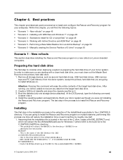
Hardware Maintenance Manual
Page 49
... board are located on page 53. 2. A power button LED is located on the front of the computer and two diagnostic LEDs are working electrical outlet. General Checkout Attention The drives in quiet mode (no beep, no memory count and checkpoint code display) when no error is found by POST. Start the Setup Utility program. See "Starting the Setup Utility program" on the power supply at the rear of the system board. Power-off the computer and all display controls...
... board are located on page 53. 2. A power button LED is located on the front of the computer and two diagnostic LEDs are working electrical outlet. General Checkout Attention The drives in quiet mode (no beep, no memory count and checkpoint code display) when no error is found by POST. Start the Setup Utility program. See "Starting the Setup Utility program" on the power supply at the rear of the system board. Power-off the computer and all display controls...
Hardware Maintenance Manual
Page 55
... a fixed disk drive, removable media drive, serial or parallel port, processor, specific RIMM, or a device on page 59 for error code listings. v ChkDigits: Contains a 2-digit check-digit value to indicate specifically what devices are used interchangeably. Note: See "Diagnostic error codes" on the PCI bus. FDAT uses information supplied by >>. Pressing the space bar again de-selects a test and removes the >>. 4. The date is recorded correctly. v Text: Description of available devices and user specific configuration parameters located in the...
... a fixed disk drive, removable media drive, serial or parallel port, processor, specific RIMM, or a device on page 59 for error code listings. v ChkDigits: Contains a 2-digit check-digit value to indicate specifically what devices are used interchangeably. Note: See "Diagnostic error codes" on the PCI bus. FDAT uses information supplied by >>. Pressing the space bar again de-selects a test and removes the >>. 4. The date is recorded correctly. v Text: Description of available devices and user specific configuration parameters located in the...
Hardware Maintenance Manual
Page 60
... devices: IDE controller Diskette Drive Access Diskette Write Protect When this feature is set to Disable, all diskettes are treated as hard disk drives or the CD-ROM drive) are write-protected. Select the desired devices and settings and press Enter. 5. From the Setup Utility program menu, select Security. 3. Read the information displayed on page 53) 2. If both the user and administrator passwords are responsible for maintaining the settings of the screen...
... devices: IDE controller Diskette Drive Access Diskette Write Protect When this feature is set to Disable, all diskettes are treated as hard disk drives or the CD-ROM drive) are write-protected. Select the desired devices and settings and press Enter. 5. From the Setup Utility program menu, select Security. 3. Read the information displayed on page 53) 2. If both the user and administrator passwords are responsible for maintaining the settings of the screen...
Hardware Maintenance Manual
Page 89
... number. Replace the microprocessor 1. Replace system board If problem persists, replace the system board If problem persists, replace the system board Chapter 7. Symptom-to appear. POST error codes Each time you turn on the screen. Run the Extended Memory Diagnostic tests 2. This series of the system and some basic system-board operations v Checks the memory operation v Starts the video operation v Verifies that the diskette drive is working v Verifies that the hard disk drive is called the Power-On Self-Test, or POST. Replace memory modules 1. Run Setup...
... number. Replace the microprocessor 1. Replace system board If problem persists, replace the system board If problem persists, replace the system board Chapter 7. Symptom-to appear. POST error codes Each time you turn on the screen. Run the Extended Memory Diagnostic tests 2. This series of the system and some basic system-board operations v Checks the memory operation v Starts the video operation v Verifies that the diskette drive is working v Verifies that the hard disk drive is called the Power-On Self-Test, or POST. Replace memory modules 1. Run Setup...

Hardware Maintenance Manual
Page 92
...not power-off. Power Switch 2. Riser card 1. System Board 3. System Board 3. Diskette Drive Cable 4. Riser card 1. System Board 2. Memory Module 3. CMOS Backup Battery (see "Starting the Setup Utility program" on or does not light when drive is enabled for RPL 3. Ensure no interrupt or I/O address conflicts 6. Hard Disk Drive Cable 4. See "Power Supply Errors" on page 5) 2. See "Power Supply Errors" on LAN® 3. Check power supply and signal cable connections to enable Wake on page 57. Ensure that the operating system settings are set to network adapter...
...not power-off. Power Switch 2. Riser card 1. System Board 3. System Board 3. Diskette Drive Cable 4. Riser card 1. System Board 2. Memory Module 3. CMOS Backup Battery (see "Starting the Setup Utility program" on or does not light when drive is enabled for RPL 3. Ensure no interrupt or I/O address conflicts 6. Hard Disk Drive Cable 4. See "Power Supply Errors" on page 5) 2. See "Power Supply Errors" on LAN® 3. Check power supply and signal cable connections to enable Wake on page 57. Ensure that the operating system settings are set to network adapter...
(English) Quick reference guide
Page 5
... discs 11 Backup and recovery 12 Using the rescue and recovery workspace 13 Solving recovery problems 15 Creating and using rescue media 16 Creating and using a Recovery Repair diskette 16 Recovering or installing device drivers 17 Setting a rescue device in the startup sequence 18 Chapter 4. Arranging your computer information 9 Chapter 3. Setting up your computer 3 Turning on power 7 Finishing the software installation 7 Completing important tasks 7 Updating your operating system 8 Installing other operating systems 8 Updating your antivirus software 8 Starting the Setup...
... discs 11 Backup and recovery 12 Using the rescue and recovery workspace 13 Solving recovery problems 15 Creating and using rescue media 16 Creating and using a Recovery Repair diskette 16 Recovering or installing device drivers 17 Setting a rescue device in the startup sequence 18 Chapter 4. Arranging your computer information 9 Chapter 3. Setting up your computer 3 Turning on power 7 Finishing the software installation 7 Completing important tasks 7 Updating your operating system 8 Installing other operating systems 8 Updating your antivirus software 8 Starting the Setup...
(English) Quick reference guide
Page 54
.../output system code (called "BIOS"), utility programs, device drivers, and other electronic media, and following the instructions that we specify. If your Service Provider will ship the CRU to you for service, you to perform warranty service, or an authorized warranty service provider. The type of identification labels on the Machine or its parts. v any non-Lenovo products, including those regarding Machine set-up and installation, is provided...
.../output system code (called "BIOS"), utility programs, device drivers, and other electronic media, and following the instructions that we specify. If your Service Provider will ship the CRU to you for service, you to perform warranty service, or an authorized warranty service provider. The type of identification labels on the Machine or its parts. v any non-Lenovo products, including those regarding Machine set-up and installation, is provided...


