User Manual
Page 8
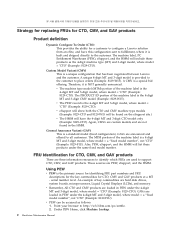
... (CMV) This is the 4-digit MT and 3-digit CMV model (Example: 8129-W15). Therefore, it is built and shipped directly to configure a Lenovo solution from an eSite, and have the 4-digit MT and 3-digit CTO model only (Example: 8129-CTO). v eSupport will show both the CTO and... custom models and are hard disk drives, system boards, microprocessors, Liquid Crystal Displays (LCDs), and memory. The MTM portion of the machine label is a unique configuration that has been negotiated between Lenovo and the customer. An example of the machine label is provided to the customer to support CTO...
... (CMV) This is the 4-digit MT and 3-digit CMV model (Example: 8129-W15). Therefore, it is built and shipped directly to configure a Lenovo solution from an eSite, and have the 4-digit MT and 3-digit CTO model only (Example: 8129-CTO). v eSupport will show both the CTO and... custom models and are hard disk drives, system boards, microprocessors, Liquid Crystal Displays (LCDs), and memory. The MTM portion of the machine label is a unique configuration that has been negotiated between Lenovo and the customer. An example of the machine label is provided to the customer to support CTO...

User Manual
Page 9
...particular machine serial (this manual 3 For the remaining FRUs (the complete list of FRUs at the following Web site: http://www.lenovo.com/support v To view the key commodities: 1. In the Refine results field, select Service parts; Important information about replacing RoHS... is displayed. hard disk drive, system board, microprocessor, LCD, and memory) v eSupport can be returned in PEW). Under Important information, click Parts information. 5. RoHS requirements must be used to http://www.lenovo.com/support. 2. The list of service parts by product, click Continue...
...particular machine serial (this manual 3 For the remaining FRUs (the complete list of FRUs at the following Web site: http://www.lenovo.com/support v To view the key commodities: 1. In the Refine results field, select Service parts; Important information about replacing RoHS... is displayed. hard disk drive, system board, microprocessor, LCD, and memory) v eSupport can be returned in PEW). Under Important information, click Parts information. 5. RoHS requirements must be used to http://www.lenovo.com/support. 2. The list of service parts by product, click Continue...
User Manual
Page 49
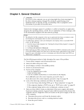
... to boot up in the computer you hear beep codes during write operations such as copying, saving, or formatting. Press the power button. © Lenovo 2005, 2009. General error messages appear if a problem or conflict is found by POST. Notes: v The default is installed on page 53. 2.... down-level BIOS might have been rearranged or the drive startup sequence changed. General Checkout Attention The drives in quiet mode (no beep, no memory count and checkpoint code display) when no error is located on the front of these messages, refer to Enhanced. v Look for displayed error ...
... to boot up in the computer you hear beep codes during write operations such as copying, saving, or formatting. Press the power button. © Lenovo 2005, 2009. General error messages appear if a problem or conflict is found by POST. Notes: v The default is installed on page 53. 2.... down-level BIOS might have been rearranged or the drive startup sequence changed. General Checkout Attention The drives in quiet mode (no beep, no memory count and checkpoint code display) when no error is located on the front of these messages, refer to Enhanced. v Look for displayed error ...

User Manual
Page 59
... various tasks are : v User Password v Administrator Password v IDE Drive User Password (some computers) v IDE Drive Master Password (some computers) You do the following sections. © Lenovo 2005, 2009. Using the Setup Utility The Setup Utility program is not displayed until you must use your computer. If you turn off the computer.... Starting the Setup Utility program To start this procedure, shut down the operating system and turn on when you might override any passwords, read -only memory (EEPROM) of each screen. b. c.
... various tasks are : v User Password v Administrator Password v IDE Drive User Password (some computers) v IDE Drive Master Password (some computers) You do the following sections. © Lenovo 2005, 2009. Using the Setup Utility The Setup Utility program is not displayed until you must use your computer. If you turn off the computer.... Starting the Setup Utility program To start this procedure, shut down the operating system and turn on when you might override any passwords, read -only memory (EEPROM) of each screen. b. c.
User Manual
Page 65
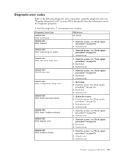
... page 516 2. System board Chapter 7. Flash the system. See "Flash update procedures" on page 516 3. System board 1. See "Flash update procedures" on page 516 2. Run memory test 4. System board 1. System board 1. System board 1. See "Flash update procedures" on page 516 3. Flash the system. See "Flash update procedures" on page 516 2. Flash...
... page 516 2. System board Chapter 7. Flash the system. See "Flash update procedures" on page 516 3. System board 1. See "Flash update procedures" on page 516 2. Run memory test 4. System board 1. System board 1. System board 1. See "Flash update procedures" on page 516 3. Flash the system. See "Flash update procedures" on page 516 2. Flash...

User Manual
Page 67
... log file 2. Flash the system. Reboot the system 2. See Chapter 6, "Using the Setup Utility," on system and re-test 2. Run Setup 2. Flash the system. Run memory test 4. Adapter card 2. System board 1. Flash the system. Re-start the test, if necessary 1. Re-run test 3. Replace the component that is called out, make...
... log file 2. Flash the system. Reboot the system 2. See Chapter 6, "Using the Setup Utility," on system and re-test 2. Run Setup 2. Flash the system. Run memory test 4. Adapter card 2. System board 1. Flash the system. Re-start the test, if necessary 1. Re-run test 3. Replace the component that is called out, make...

User Manual
Page 74
.... Press F3 to "Undetermined problems" on page 53 2. See Chapter 6, "Using the Setup Utility," on page 516 3. See "Flash update procedures" on page 516 3. Run memory test 4. Make sure the component that is connected and/or enabled. Run setup and check for conflicts 2. Flash the system. Flash the system and re...
.... Press F3 to "Undetermined problems" on page 53 2. See Chapter 6, "Using the Setup Utility," on page 516 3. See "Flash update procedures" on page 516 3. Run memory test 4. Make sure the component that is connected and/or enabled. Run setup and check for conflicts 2. Flash the system. Flash the system and re...
User Manual
Page 83
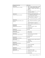
... test 2. If a component is called out, make sure it is called out in warning statement 4. See "Flash update procedures" on page 88 1. Replace the memory module called out is connected and/or enabled. Diagnostic Error Code 175-197-XXX Thermal Sensor(s) test warning 175-198-XXX Thermal Sensor(s) test aborted...XXX Asset Security Test Passed 185-XXX-XXX Asset Security failure 185-278-XXX Asset Security Chassis Intrusion 201-000-XXX System Memory Test Passed 201-XXX-XXX System Memory error 202-000-XXX System Cache Test Passed 202-XXX-XXX System Cache error 206-000-XXX Diskette Drive Test Passed ...
... test 2. If a component is called out, make sure it is called out in warning statement 4. See "Flash update procedures" on page 88 1. Replace the memory module called out is connected and/or enabled. Diagnostic Error Code 175-197-XXX Thermal Sensor(s) test warning 175-198-XXX Thermal Sensor(s) test aborted...XXX Asset Security Test Passed 185-XXX-XXX Asset Security failure 185-278-XXX Asset Security Chassis Intrusion 201-000-XXX System Memory Test Passed 201-XXX-XXX System Memory error 202-000-XXX System Cache Test Passed 202-XXX-XXX System Cache error 206-000-XXX Diskette Drive Test Passed ...
User Manual
Page 86
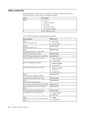
Run Setup 2. Memory module 2. System Board 1. Memory module 2. Keyboard 1. Beep symptoms Beep symptoms are short tones or a series of breaks Four continuous beeps Use the following examples.... interrupt mask register failed 2-1-4 Secondary interrupt mask register failed 2-2-1 Interrupt vector loading failed 1-3-1-3 Keyboard controller failed 2-2-3 CMOS power failure and checksum checks failed FRU/Action 1. Memory module 2. System Board System board System board System board System board 1. Battery 2. Beeps 1-2-X 4 Description v One beep v A pause (or break) v Two beeps v A ...
Run Setup 2. Memory module 2. System Board 1. Memory module 2. Keyboard 1. Beep symptoms Beep symptoms are short tones or a series of breaks Four continuous beeps Use the following examples.... interrupt mask register failed 2-1-4 Secondary interrupt mask register failed 2-2-1 Interrupt vector loading failed 1-3-1-3 Keyboard controller failed 2-2-3 CMOS power failure and checksum checks failed FRU/Action 1. Memory module 2. System Board System board System board System board System board 1. Battery 2. Beeps 1-2-X 4 Description v One beep v A pause (or break) v Two beeps v A ...

User Manual
Page 87
Battery 2. Keyboard Cable 3. Beep Symptom 2-2-4 CMOS configuration info validation failed 2-3-1 Screen initialization failed 2-3-2 Screen memory failed 2-3-3 Screen retrace failed 1-2 Search for video ROM failed All other beep code sequences Continuous beep Repeating short beeps FRU/Action 1. Symptom-to-FRU Index 81 Jumper on J28 2. System Board System board System board System board System board System Board 1. Keyboard stuck key 2. System Board 1. System Board Chapter 7.
Battery 2. Keyboard Cable 3. Beep Symptom 2-2-4 CMOS configuration info validation failed 2-3-1 Screen initialization failed 2-3-2 Screen memory failed 2-3-3 Screen retrace failed 1-2 Search for video ROM failed All other beep code sequences Continuous beep Repeating short beeps FRU/Action 1. Symptom-to-FRU Index 81 Jumper on J28 2. System Board System board System board System board System board System Board 1. Keyboard stuck key 2. System Board 1. System Board Chapter 7.
User Manual
Page 88
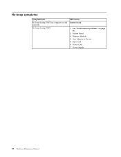
System Board 3. Power Supply 82 Hardware Maintenance Manual Any Adapter or Device 5. Riser Card 6. No beep during POST but computer works correctly. See "Undetermined problems" on page 88. 2. Memory Module 4. No-beep symptoms Symptom/Error No beep during POST. FRU/Action System board 1. Power Cord 7.
System Board 3. Power Supply 82 Hardware Maintenance Manual Any Adapter or Device 5. Riser Card 6. No beep during POST but computer works correctly. See "Undetermined problems" on page 88. 2. Memory Module 4. No-beep symptoms Symptom/Error No beep during POST. FRU/Action System board 1. Power Cord 7.
User Manual
Page 89
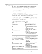
... in BIOS. RFID Antenna 3. Symptom-to update the BIOS level 2. v Checks some options. System board 1. POST Error Code 162 Configuration error 164 Memory Size Error 166 Boot Block Check Sum Error 167 No Processor BIOS update found 175 Primary Copy of Secure Data is called the Power-On...power-on the system, it performs a series of tests that check the operation of the system and some basic system-board operations v Checks the memory operation v Starts the video operation v Verifies that the diskette drive is working v Verifies that the hard disk drive is working If the POST...
... in BIOS. RFID Antenna 3. Symptom-to update the BIOS level 2. v Checks some options. System board 1. POST Error Code 162 Configuration error 164 Memory Size Error 166 Boot Block Check Sum Error 167 No Processor BIOS update found 175 Primary Copy of Secure Data is called the Power-On...power-on the system, it performs a series of tests that check the operation of the system and some basic system-board operations v Checks the memory operation v Starts the video operation v Verifies that the diskette drive is working v Verifies that the hard disk drive is working If the POST...
User Manual
Page 90
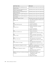
... Keyboard stuck key error 1. Run hard disk drive diagnostics. 3. Check for stuck keys 2. Run Setup and verify PCI/ISA Available configuration settings. 2. Run Enhanced Diagnostics Memory Test 2. Replace the battery and run Setup. 1762 Configuration Change has occurred 1. Make sure keyboard is dead 1. POST Error Code FRU/Action 191 System Security...: Asset ID Antenna has If problem persists, replace the system board been installed 196 System Tampered Cleared If problem persists, replace the system board 201 Memory error 1. Memory module 3.
... Keyboard stuck key error 1. Run hard disk drive diagnostics. 3. Check for stuck keys 2. Run Setup and verify PCI/ISA Available configuration settings. 2. Run Enhanced Diagnostics Memory Test 2. Replace the battery and run Setup. 1762 Configuration Change has occurred 1. Make sure keyboard is dead 1. POST Error Code FRU/Action 191 System Security...: Asset ID Antenna has If problem persists, replace the system board been installed 196 System Tampered Cleared If problem persists, replace the system board 201 Memory error 1. Memory module 3.
User Manual
Page 91
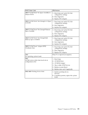
...! Run Setup and verify PCI/ISA configuration settings. 2. Run diagnostics. 3. Not Enough I/O Space Available 1. Run diagnostics. 3. Not Enough Memory Space Available 1. Run Setup and verify PCI/ISA configuration settings. 2. Not Enough Real Memory Space Available 1. Run Setup and verify PCI/ISA configuration settings. 2. Replace PCI Adapter 1805 PCI/PnP Error! Run Setup...
...! Run Setup and verify PCI/ISA configuration settings. 2. Run diagnostics. 3. Not Enough I/O Space Available 1. Run diagnostics. 3. Not Enough Memory Space Available 1. Run Setup and verify PCI/ISA configuration settings. 2. Not Enough Real Memory Space Available 1. Run Setup and verify PCI/ISA configuration settings. 2. Replace PCI Adapter 1805 PCI/PnP Error! Run Setup...
User Manual
Page 92
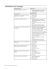
... adapter (advise network administrator of new MAC address) 1. Diskette Drive 2. Run the Memory tests 2. System Board 3. Hard Disk Drive Cable 4. See "Power Supply Errors" on page 5) 2. Incorrect memory size during POST FRU/Action 1. Ensure that the operating system settings are set to ... Battery (see "Starting the Setup Utility program" on page 53) 4. System Board 3. Flashing cursor with an otherwise blank display. Memory Module 3. System Board Display/Monitor 1. Ensure network administrator is enabled for RPL 3. Power Switch 2. Ensure that network adapter is using...
... adapter (advise network administrator of new MAC address) 1. Diskette Drive 2. Run the Memory tests 2. System Board 3. Hard Disk Drive Cable 4. See "Power Supply Errors" on page 5) 2. Incorrect memory size during POST FRU/Action 1. Ensure that the operating system settings are set to ... Battery (see "Starting the Setup Utility program" on page 53) 4. System Board 3. Flashing cursor with an otherwise blank display. Memory Module 3. System Board Display/Monitor 1. Ensure network administrator is enabled for RPL 3. Power Switch 2. Ensure that network adapter is using...
User Manual
Page 94
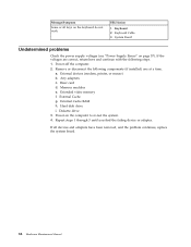
... Supply Errors" on the keyboard do not work FRU/Action 1. Hard disk drive i. Remove or disconnect the following steps. 1. Extended video memory f. Power-on the computer to re-test the system. 4. Keyboard 2. If the voltages are correct, return here and continue with the ...following components (if installed) one at a time. Memory modules e. External Cache RAM h. Repeat steps 1 through 3 until you find the failing device or adapter. Power-off the computer. 2. Riser card d....
... Supply Errors" on the keyboard do not work FRU/Action 1. Hard disk drive i. Remove or disconnect the following steps. 1. Extended video memory f. Power-on the computer to re-test the system. 4. Keyboard 2. If the voltages are correct, return here and continue with the ...following components (if installed) one at a time. Memory modules e. External Cache RAM h. Repeat steps 1 through 3 until you find the failing device or adapter. Power-off the computer. 2. Riser card d....
User Manual
Page 115
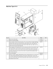
... 36Y 37S 37P 37Y G6S G6P G6Y G7S G7P G7Y 81S 81P 81Y 82S 82P 82Y 53S 53P 53Y 54S 54P 54Y) 4 Cover (all models) 5 Memory module, 256MB, DDR2 SDRAM, NP (PC 4200) (models CTO A1J A2J A3J B1A B1Q B1T B2K B3K B4K B5K B6G 21K 22K 23K 34K 35K...
... 36Y 37S 37P 37Y G6S G6P G6Y G7S G7P G7Y 81S 81P 81Y 82S 82P 82Y 53S 53P 53Y 54S 54P 54Y) 4 Cover (all models) 5 Memory module, 256MB, DDR2 SDRAM, NP (PC 4200) (models CTO A1J A2J A3J B1A B1Q B1T B2K B3K B4K B5K B6G 21K 22K 23K 34K 35K...
User Manual
Page 147
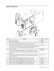
... 34Q 35Q 36Q 37Q 39Q 3AQ 3BQ 3CQ A1V B1V B2V D1V E1V E2Q F1Q F2Q H1Q H2Q J1Q K1Q 24Q G1Q) 4 Cover (all models) 5 Memory module, 256MB, DDR2 SDRAM, NP (PC 4200) (models CTO 21Q 22A 22Q 22T 23C 23B 23H 23V 31C 31B 31H 31V 32A 32Q 32T 22S... 22P 22Y 32S 32P 32Y 34Q 35Q 36Q 37Q A1V B1V B2V D1V E1V H1A H1Q H1T J1A J1Q J1T 24A 24Q 24T) 5 Memory module, 512MB, DDR2 SDRAM, NP (PC 4200) (models CTO 33Q 39Q 3AQ 3BQ 3CQ E2A E2Q E2T F1A F1Q F1T F2A F2Q F2T H2A H2Q...
... 34Q 35Q 36Q 37Q 39Q 3AQ 3BQ 3CQ A1V B1V B2V D1V E1V E2Q F1Q F2Q H1Q H2Q J1Q K1Q 24Q G1Q) 4 Cover (all models) 5 Memory module, 256MB, DDR2 SDRAM, NP (PC 4200) (models CTO 21Q 22A 22Q 22T 23C 23B 23H 23V 31C 31B 31H 31V 32A 32Q 32T 22S... 22P 22Y 32S 32P 32Y 34Q 35Q 36Q 37Q A1V B1V B2V D1V E1V H1A H1Q H1T J1A J1Q J1T 24A 24Q 24T) 5 Memory module, 512MB, DDR2 SDRAM, NP (PC 4200) (models CTO 33Q 39Q 3AQ 3BQ 3CQ E2A E2Q E2T F1A F1Q F1T F2A F2Q F2T H2A H2Q...
User Manual
Page 188
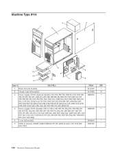
... D1S D1P D1L D1Q D1C D1B D1H D1V D2C E9S E9P E9L E9D E9Y E9Q E9C E9B E9H E9V EAC F2C 82Q) 4 Cover (all models) 5 Memory module, 256MB, DDR2 SDRAM, NP (PC 4200) (models CTO 11M D2C EAC F2C) FRU# 41A7107 41A7808 24R2596 24R2598 39M0465 30R5120 CRU * N ** ** * * 182 Hardware Maintenance Manual
... D1S D1P D1L D1Q D1C D1B D1H D1V D2C E9S E9P E9L E9D E9Y E9Q E9C E9B E9H E9V EAC F2C 82Q) 4 Cover (all models) 5 Memory module, 256MB, DDR2 SDRAM, NP (PC 4200) (models CTO 11M D2C EAC F2C) FRU# 41A7107 41A7808 24R2596 24R2598 39M0465 30R5120 CRU * N ** ** * * 182 Hardware Maintenance Manual
User Manual
Page 205
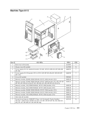
...) 3 Power supply, 310 W (models CTO-A CTO-L 45S 45P 45L 45Q 45C 45B 45H 45V 45D 45Y) 4 Cover (all models) 5 Memory module, 256MB, DDR2 SDRAM, NP (PC 4200) (models CTO) 5 Memory module, 512MB, DDR2 SDRAM, NP (PC 4200) (models CTO 45U 45F 45S 45P 45L 45G 45M 45A 45Q 45T 45C 45B...45V 45K 45R 45E 45J 45D 45Y) 5 Memory module, 1GB, DDR2 SDRAM, NP (PC 4200) (models CTO) 5 Memory module, 2GB, DDR2 SDRAM, NP (PC 4200) (models CTO) 5 Memory module, 256MB, DDR2 SDRAM, NP (PC 5300) (models CTO) 5 Memory module, 512MB, DDR2 SDRAM, NP (PC 5300) (models CTO) 5 Memory module, 1GB, DDR2 SDRAM, NP (PC ...
...) 3 Power supply, 310 W (models CTO-A CTO-L 45S 45P 45L 45Q 45C 45B 45H 45V 45D 45Y) 4 Cover (all models) 5 Memory module, 256MB, DDR2 SDRAM, NP (PC 4200) (models CTO) 5 Memory module, 512MB, DDR2 SDRAM, NP (PC 4200) (models CTO 45U 45F 45S 45P 45L 45G 45M 45A 45Q 45T 45C 45B...45V 45K 45R 45E 45J 45D 45Y) 5 Memory module, 1GB, DDR2 SDRAM, NP (PC 4200) (models CTO) 5 Memory module, 2GB, DDR2 SDRAM, NP (PC 4200) (models CTO) 5 Memory module, 256MB, DDR2 SDRAM, NP (PC 5300) (models CTO) 5 Memory module, 512MB, DDR2 SDRAM, NP (PC 5300) (models CTO) 5 Memory module, 1GB, DDR2 SDRAM, NP (PC ...


