

Service Manual
Page 1
website:http://biz.LGservice.com e-mail:http://www.LGEservice.com/techsup.html LCD TV SERVICE MANUAL CHASSIS : ML-041A MODEL : RZ-32LZ50 CAUTION BEFORE SERVICING THE CHASSIS, READ THE SAFETY PRECAUTIONS IN THIS MANUAL.
website:http://biz.LGservice.com e-mail:http://www.LGEservice.com/techsup.html LCD TV SERVICE MANUAL CHASSIS : ML-041A MODEL : RZ-32LZ50 CAUTION BEFORE SERVICING THE CHASSIS, READ THE SAFETY PRECAUTIONS IN THIS MANUAL.

Service Manual
Page 3
... should be checked and repaired before the receiver is returned to be replaced with the specified. In case any fuse (or Fusible Resistor) in this manual to prevent X-RADIATION, Shock, Fire, or other ohm-meter lead in turn to the chassis the reading must be inadvertently introduced during the service operation...
... should be checked and repaired before the receiver is returned to be replaced with the specified. In case any fuse (or Fusible Resistor) in this manual to prevent X-RADIATION, Shock, Fire, or other ohm-meter lead in turn to the chassis the reading must be inadvertently introduced during the service operation...

Service Manual
Page 4
...solder removal device or with an anti-static, suction- a. c. SERVICING PRECAUTIONS CAUTION: Before servicing receivers covered by this service manual and its supplements and addenda, read and follow the safety precautions. General Servicing Precautions 1. Always unplug the receiver AC power cord...assembly into which receivers covered by applying the following soldering technique. d. c. Connecting a test substitute in parallel with this service manual. CAUTION: Do not connect the test fixture ground strap to 600¡F£. 2. After removing an electrical assembly equipped ...
...solder removal device or with an anti-static, suction- a. c. SERVICING PRECAUTIONS CAUTION: Before servicing receivers covered by this service manual and its supplements and addenda, read and follow the safety precautions. General Servicing Precautions 1. Always unplug the receiver AC power cord...assembly into which receivers covered by applying the following soldering technique. d. c. Connecting a test substitute in parallel with this service manual. CAUTION: Do not connect the test fixture ground strap to 600¡F£. 2. After removing an electrical assembly equipped ...
Service Manual
Page 12
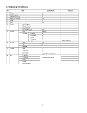
3. Shipping Conditions NO ITEM 1 Power 2 Volume Level 3 Main Pcture Input 5 Main Last Channel 8 Mute 9 ARC 10 Station Auto Program Manual Program Program Edit Favorite Program 11 Picture PSM Dynamic Contrast Brightness Colour Sharpness Tint 14 Sound SSM AVL Balance 15 Special Input Child Lock Auto sleep Language 16 PC H-Position V-Position Clock Phase Auto Configure Off 30 TV Pr 01 Off 16:9 CONDITION None Dynamic 80 40 70 70 0 Flat Off 0 TV Off Off English(Area Management) Variable by each mode REMARK NTSC OPTION - 12 -
3. Shipping Conditions NO ITEM 1 Power 2 Volume Level 3 Main Pcture Input 5 Main Last Channel 8 Mute 9 ARC 10 Station Auto Program Manual Program Program Edit Favorite Program 11 Picture PSM Dynamic Contrast Brightness Colour Sharpness Tint 14 Sound SSM AVL Balance 15 Special Input Child Lock Auto sleep Language 16 PC H-Position V-Position Clock Phase Auto Configure Off 30 TV Pr 01 Off 16:9 CONDITION None Dynamic 80 40 70 70 0 Flat Off 0 TV Off Off English(Area Management) Variable by each mode REMARK NTSC OPTION - 12 -

Service Manual
Page 14
... a) Input User Info Data b) Click "Update" button c) Click " Write" button e) Click Start button. EDID Read & Write 1) Run WinEDID.exe 1. EDID ADJUSTMENT Windows EDID V1.0 User Manual Operating System: MS Windows 98, 2000, XP Port Setup: Windows 98 => Don't need setup Windows 2000, XP => Need to Port Setup. Cable Connection - 14 -
... a) Input User Info Data b) Click "Update" button c) Click " Write" button e) Click Start button. EDID Read & Write 1) Run WinEDID.exe 1. EDID ADJUSTMENT Windows EDID V1.0 User Manual Operating System: MS Windows 98, 2000, XP Port Setup: Windows 98 => Don't need setup Windows 2000, XP => Need to Port Setup. Cable Connection - 14 -

Service Manual
Page 15
... updated.) 35 MODE 36 PIP 37 TILT 38 0~9 Used as Mode in the teletext mode To select the simultaneous screen To adjust screen tilt To manually select the channel. To set . Use the AV 12 IN-START To adjust the screen voltage (automatic): key to match the surrounding brightness so natural...
... updated.) 35 MODE 36 PIP 37 TILT 38 0~9 Used as Mode in the teletext mode To select the simultaneous screen To adjust screen tilt To manually select the channel. To set . Use the AV 12 IN-START To adjust the screen voltage (automatic): key to match the surrounding brightness so natural...

Service Manual
Page 1
website:http://biz.LGservice.com e-mail:http://www.LGEservice.com/techsup.html LCD TV SERVICE MANUAL CHASSIS : ML-051B MODEL : RZ/RT-37LZ55 CAUTION BEFORE SERVICING THE CHASSIS, READ THE SAFETY PRECAUTIONS IN THIS MANUAL.
website:http://biz.LGservice.com e-mail:http://www.LGEservice.com/techsup.html LCD TV SERVICE MANUAL CHASSIS : ML-051B MODEL : RZ/RT-37LZ55 CAUTION BEFORE SERVICING THE CHASSIS, READ THE SAFETY PRECAUTIONS IN THIS MANUAL.

Service Manual
Page 3
... the AC cord into the AC outlet. Any voltage measured must not exceed 0.75 volt RMS which is returned to be inadvertently introduced during this manual to prevent Shock, Fire, or other abnormality exists that may be sure the set must be used during the servicing of ohm-meter to the...
... the AC cord into the AC outlet. Any voltage measured must not exceed 0.75 volt RMS which is returned to be inadvertently introduced during this manual to prevent Shock, Fire, or other abnormality exists that may be sure the set must be used during the servicing of ohm-meter to the...

Service Manual
Page 4
...connection. Do not defeat any plug/socket B+ voltage interlocks with this receiver only the test fixtures specified in this service manual might be equipped. 6. Such components commonly are integrated circuits and some field-effect transistors and semiconductor "chip" components....electricity sufficient to 600 F) b. Alternatively, obtain and wear a commercially available discharging wrist strap device, which receivers covered by this service manual. Do not remove a replacement ES device from a carpeted floor can be soldered. Do not use freon-propelled chemicals. Use the ...
...connection. Do not defeat any plug/socket B+ voltage interlocks with this receiver only the test fixtures specified in this service manual might be equipped. 6. Such components commonly are integrated circuits and some field-effect transistors and semiconductor "chip" components....electricity sufficient to 600 F) b. Alternatively, obtain and wear a commercially available discharging wrist strap device, which receivers covered by this service manual. Do not remove a replacement ES device from a carpeted floor can be soldered. Do not use freon-propelled chemicals. Use the ...

Service Manual
Page 12
...B4 80 80 7E 37 Default Value 42 => Before White-Balance, the AV ADC should be done. (RZ : AV, RT : AV1, RM : VIDEO1) Notice : Before White-Balance, change input mode - white Balance 5.1 Manual white Balance (AV) 1) Execute CA-110 Zero Calibration. 2) Execute the SET Heat Run for 30minutes ...-RGB OK means the adjustment is completed. 4.2 Adjustment of Auto RF/AV/S-VIDEO Color Balance. 1) Input the Video Signal: 75% Color Bar signal into Component. (RZ : component , RT/RM : component 1 or 2) 2) Set the PSM to Standard mode in the Picture menu. 3) Press ADJ key on R/C for adjustment. 4) Press...
...B4 80 80 7E 37 Default Value 42 => Before White-Balance, the AV ADC should be done. (RZ : AV, RT : AV1, RM : VIDEO1) Notice : Before White-Balance, change input mode - white Balance 5.1 Manual white Balance (AV) 1) Execute CA-110 Zero Calibration. 2) Execute the SET Heat Run for 30minutes ...-RGB OK means the adjustment is completed. 4.2 Adjustment of Auto RF/AV/S-VIDEO Color Balance. 1) Input the Video Signal: 75% Color Bar signal into Component. (RZ : component , RT/RM : component 1 or 2) 2) Set the PSM to Standard mode in the Picture menu. 3) Press ADJ key on R/C for adjustment. 4) Press...

Service Manual
Page 13
Shipping Conditions No 1 2 3 4 5 6 7 Power Volume Level Main Picture Input Main Last Channel Mute ARC Station Auto Program Manual Program Program Edit Favorite Program 8 Picture PSM Dynamic Contrast Brightness Colour Sharpness CSM XD ACM None Dynamic 100 45 50 50 Normal(Cool) On Fleshtone : 1 ... TV Speaker 10 Time Clock Off time On time Auto sleep 11 Special Input Language Child Lock Set ID XD Demo 12 Screen Auto config Manual config XGA Mode ARC Zoom +/Position Cinema NR Reset Variable by each mode Flat Off Off 0 50 50 On -- : -Off Off Off TV English Off...
Shipping Conditions No 1 2 3 4 5 6 7 Power Volume Level Main Picture Input Main Last Channel Mute ARC Station Auto Program Manual Program Program Edit Favorite Program 8 Picture PSM Dynamic Contrast Brightness Colour Sharpness CSM XD ACM None Dynamic 100 45 50 50 Normal(Cool) On Fleshtone : 1 ... TV Speaker 10 Time Clock Off time On time Auto sleep 11 Special Input Language Child Lock Set ID XD Demo 12 Screen Auto config Manual config XGA Mode ARC Zoom +/Position Cinema NR Reset Variable by each mode Flat Off Off 0 50 50 On -- : -Off Off Off TV English Off...

Service Manual
Page 14
... if the power is updated.) Used as Mode in the teletext mode MODE To select the simultaneous screen PIP To adjust screen tilt TILT To manually select the channel. 0~9 POWER Shortcut keys Shortcut keys Shortcut keys 12 Use the AV key to match EYE the surrounding brightness so natural color can...
... if the power is updated.) Used as Mode in the teletext mode MODE To select the simultaneous screen PIP To adjust screen tilt TILT To manually select the channel. 0~9 POWER Shortcut keys Shortcut keys Shortcut keys 12 Use the AV key to match EYE the surrounding brightness so natural color can...


