
Service Manual
Page 2
... on all ovens to be performed on microwave power for any service test or inspection within the microwave generating compartments, check the magnetron, wave guide or transmission line, and cavity for precautions to be repaired, replaced, or adjusted by properly qualified service personnel. SAFETY PRECAUTIONS This device is released to the owner. Consult the service manual for proper service procedures to assure continued safety operation and...
... on all ovens to be performed on microwave power for any service test or inspection within the microwave generating compartments, check the magnetron, wave guide or transmission line, and cavity for precautions to be repaired, replaced, or adjusted by properly qualified service personnel. SAFETY PRECAUTIONS This device is released to the owner. Consult the service manual for proper service procedures to assure continued safety operation and...

Service Manual
Page 4
.... 1-1 SPECIFICATIONS ITEM MODEL Power Requirement Power Output Microwave Frequency Magnetron Timer Outside Dimensions Cavity Dimensions Net Weight Shipping weight Control Complement DESCRIPTION MB-387W 230 Volts AC 50 Hz Single phase, 3 wire grounded Microwave 1,200W Gril 1,000W Combination 2,150W 800 Watts full microwave power (IEC60705) 2,450 MHz 2M214 - 240GP 0 ~ 90 min. 455 (W) x 281 (H) x 313 (D) mm 312 (W) x 203 (H) x 293 (D) mm 13 kg (approx) 14.2 kg (approx) Microwave Power for Variable Cooking Power level MAX Full power throughout the cooking time...
.... 1-1 SPECIFICATIONS ITEM MODEL Power Requirement Power Output Microwave Frequency Magnetron Timer Outside Dimensions Cavity Dimensions Net Weight Shipping weight Control Complement DESCRIPTION MB-387W 230 Volts AC 50 Hz Single phase, 3 wire grounded Microwave 1,200W Gril 1,000W Combination 2,150W 800 Watts full microwave power (IEC60705) 2,450 MHz 2M214 - 240GP 0 ~ 90 min. 455 (W) x 281 (H) x 313 (D) mm 312 (W) x 203 (H) x 293 (D) mm 13 kg (approx) 14.2 kg (approx) Microwave Power for Variable Cooking Power level MAX Full power throughout the cooking time...

Service Manual
Page 5
... injure the door seal and front plate of the oven cavity. • NEVER put iron tools on a 2-wire extension cord during operation. • BEFORE TOUCHING any parts of the oven, always remove the power plug from the magnetron or other appliances, the microwave oven is high-voltage and high-current equipment. ANTENNA Gasket FILAMENT TERMINALS COOLING FIN MAGNETRON CHASSIS GROUND MAGNETRON THE OVEN IS TO BE SERVICED ONLY...
... injure the door seal and front plate of the oven cavity. • NEVER put iron tools on a 2-wire extension cord during operation. • BEFORE TOUCHING any parts of the oven, always remove the power plug from the magnetron or other appliances, the microwave oven is high-voltage and high-current equipment. ANTENNA Gasket FILAMENT TERMINALS COOLING FIN MAGNETRON CHASSIS GROUND MAGNETRON THE OVEN IS TO BE SERVICED ONLY...

Service Manual
Page 6
...-and-yellow. Use care when handling.) 3. The oven should not be connected to the terminal in any area where heat and steam are colored in accordance with the letter N or colored black. Blocking vent or air intake openings can cause damage to a conventional surface unit or above a conventional wall oven. 5. This glass is properly earthed before servicing 2. The wire which is marked...
...-and-yellow. Use care when handling.) 3. The oven should not be connected to the terminal in any area where heat and steam are colored in accordance with the letter N or colored black. Blocking vent or air intake openings can cause damage to a conventional surface unit or above a conventional wall oven. 5. This glass is properly earthed before servicing 2. The wire which is marked...

Service Manual
Page 7
AUTO DEFROST: Used to cook the foods listed by one touch. 3. STOP/CLEAR: Used to stop over to set the time of day. 7. START/QUICK START: One tap allows over and clear all entries except time of day. 8. DIAL: 4-1 AUTO COOK: Used to select the auto weight defrost. 5. INDICATORS 4. POWER: Used to select the auto weight defrost. 6. CLOCK: Used to begin functioning. 9. OPERATING INSTRUCTIONS FEATURES Oven Front Plate Window Door Screen Door Seal Control Panel Grill Rack CONTROL PANEL 480W 320W 640W 160W 1 800W 2 3 7 4 5 8 6 9 Safety Door Lock System Turntable...
AUTO DEFROST: Used to cook the foods listed by one touch. 3. STOP/CLEAR: Used to stop over to set the time of day. 7. START/QUICK START: One tap allows over and clear all entries except time of day. 8. DIAL: 4-1 AUTO COOK: Used to select the auto weight defrost. 5. INDICATORS 4. POWER: Used to select the auto weight defrost. 6. CLOCK: Used to begin functioning. 9. OPERATING INSTRUCTIONS FEATURES Oven Front Plate Window Door Screen Door Seal Control Panel Grill Rack CONTROL PANEL 480W 320W 640W 160W 1 800W 2 3 7 4 5 8 6 9 Safety Door Lock System Turntable...

Service Manual
Page 8
MICROWAVE COOKING Stop Micro Time Start 5. GRILL COOKING Stop Grill Time Start 6. AUTO WEIGHT DEFROST Stop Desired defrost category Number of component functions during oven operation. 1. QUICK START Stop Start 4. CHILD LOCK This oven has a CHILD LOCK feature • TO SET CHILD LOCK • Touch the Stop pad • Touch STOP pad L appear in use. COMBI COOKING Stop Combi Time Start 7. AUTO COOK Stop Auto cook Start 9. SETTING THE CLOCK Stop Clock Number Clock NOTE: You can set 12 hour clock or 24 hour clock optionally. 2. CANCEL FUNCTION ...
MICROWAVE COOKING Stop Micro Time Start 5. GRILL COOKING Stop Grill Time Start 6. AUTO WEIGHT DEFROST Stop Desired defrost category Number of component functions during oven operation. 1. QUICK START Stop Start 4. CHILD LOCK This oven has a CHILD LOCK feature • TO SET CHILD LOCK • Touch the Stop pad • Touch STOP pad L appear in use. COMBI COOKING Stop Combi Time Start 7. AUTO COOK Stop Auto cook Start 9. SETTING THE CLOCK Stop Clock Number Clock NOTE: You can set 12 hour clock or 24 hour clock optionally. 2. CANCEL FUNCTION ...

Service Manual
Page 10
... monitor switch opens (contact COM and NO). power of microwave oven as shown by the solid line. voltage is applied to indicate that the stage has been set. GRILL THERMOSTAT L L G -Y E N N GRILL HEATER RELAY 3 • Turntable rotates. • The fan motor rotates. • The air is also directed into the oven to exhaust the vapor in the oven through the base plate and upper plate. 4-4 WHEN THE OVEN IS SET...
... monitor switch opens (contact COM and NO). power of microwave oven as shown by the solid line. voltage is applied to indicate that the stage has been set. GRILL THERMOSTAT L L G -Y E N N GRILL HEATER RELAY 3 • Turntable rotates. • The fan motor rotates. • The air is also directed into the oven to exhaust the vapor in the oven through the base plate and upper plate. 4-4 WHEN THE OVEN IS SET...
Service Manual
Page 11
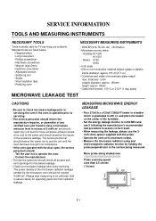
... (size 5mm) • Adjustable wrench • Soldering iron • Solder • Vinyl insulation tape • Polishing cloth NECESSARY MEASURING INSTRUMENTS • TESTER(VOLTS-DC, AC., Ohmmeter) • Microwave survey meter - Always start measuring of the microwave radiation leakage emitted by the microwave oven should instruct the owner not to use the 2inch (5cm) spacer supplied with the door open, the service personnel...
... (size 5mm) • Adjustable wrench • Soldering iron • Solder • Vinyl insulation tape • Polishing cloth NECESSARY MEASURING INSTRUMENTS • TESTER(VOLTS-DC, AC., Ohmmeter) • Microwave survey meter - Always start measuring of the microwave radiation leakage emitted by the microwave oven should instruct the owner not to use the 2inch (5cm) spacer supplied with the door open, the service personnel...
Service Manual
Page 12
... handle. Also enter the information on the service invoice. • The microwave energy leakage should be removed no faster than 2 mW/cm.sq. 5-2 MEASUREMENT WITH A FULLY ASSEMBLED OVEN • After all parts are in good condition, functioning properly and genuine replacement parts which are listed in a slightly opened position-less than 1 inch/sec (2.5 cm/sec) along the oven surface, this manual have been used...
... handle. Also enter the information on the service invoice. • The microwave energy leakage should be removed no faster than 2 mW/cm.sq. 5-2 MEASUREMENT WITH A FULLY ASSEMBLED OVEN • After all parts are in good condition, functioning properly and genuine replacement parts which are listed in a slightly opened position-less than 1 inch/sec (2.5 cm/sec) along the oven surface, this manual have been used...
Service Manual
Page 13
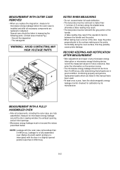
... lowest position and the microwave power switched on. • The time T for the earth and securing the control panel. 3) Lift control panel ASS'Y from the rear and along side edges of the earth terminal. OUTER CASE REMOVAL C. B. It is measured immediately before the water is the temperature rise. CONTROL PANEL ASSEMBLY 1) Disconnect the power supply cord from the outlet. 2) Remove the screws from the oven by a value ∆...
... lowest position and the microwave power switched on. • The time T for the earth and securing the control panel. 3) Lift control panel ASS'Y from the rear and along side edges of the earth terminal. OUTER CASE REMOVAL C. B. It is measured immediately before the water is the temperature rise. CONTROL PANEL ASSEMBLY 1) Disconnect the power supply cord from the outlet. 2) Remove the screws from the oven by a value ∆...

Service Manual
Page 15
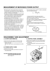
AIR DUCT ASSEMBLY REMOVAL 1) Disconnect the leadwire from lamp, A.C Relay and monitor resistor and magnetron. 2) Remove the screw to grasp the connector, not the wires, when removing. MAGNETRON REMOVAL 1) Disconnect the leadwire from the turntable motor terminals. 6) Remove the screw securing the turntable motor to the oven cavity ASS'Y 7) After repairing the motor, rotate the removed turntable motor cover. 8) Fit the turntable motor cover's projecting part to the base plate slit. After replacing the magnetron, check for microwave leakage with a wire cutting. 5) Disconnect the leadwire...
AIR DUCT ASSEMBLY REMOVAL 1) Disconnect the leadwire from lamp, A.C Relay and monitor resistor and magnetron. 2) Remove the screw to grasp the connector, not the wires, when removing. MAGNETRON REMOVAL 1) Disconnect the leadwire from the turntable motor terminals. 6) Remove the screw securing the turntable motor to the oven cavity ASS'Y 7) After repairing the motor, rotate the removed turntable motor cover. 8) Fit the turntable motor cover's projecting part to the base plate slit. After replacing the magnetron, check for microwave leakage with a wire cutting. 5) Disconnect the leadwire...

Service Manual
Page 16
... have any play in it when the door is opened during cooking and thus to prevent the danger resulting from the microwave leakage. 2) MOUNTING OF THE PRIMARY/MONITOR/ SECONDARY SWITCHES TO THE LATCH BOARD ADJUSTMENT DIRECTION PRIMARY SWITCH MONITOR SWITCH SECONDARY SWITCH 3) INSTALLATION AND ADJUSTMENT OF THE LATCH BOARD TO THE OVEN ASSEMBLY • Mount the latch board to the control panel. 3) Disconnect the flat cable from the PCB...
... have any play in it when the door is opened during cooking and thus to prevent the danger resulting from the microwave leakage. 2) MOUNTING OF THE PRIMARY/MONITOR/ SECONDARY SWITCHES TO THE LATCH BOARD ADJUSTMENT DIRECTION PRIMARY SWITCH MONITOR SWITCH SECONDARY SWITCH 3) INSTALLATION AND ADJUSTMENT OF THE LATCH BOARD TO THE OVEN ASSEMBLY • Mount the latch board to the control panel. 3) Disconnect the flat cable from the PCB...

Service Manual
Page 22
... careful of microwave by their characteristics. Low AC input voltage. THIS CAN ELIMINATE AN UNNECESSARY SERVICE CALL. CAUSE Inserting many plug into one lead wire from these parts and then check continuity with the AC plug removed. Excessive weight on the digital programmer circuit since static electric discharge may not be cooked for a longer time period. Wrap the thinner part with metallic trimming. 1. TROUBLE SHOOTING...
... careful of microwave by their characteristics. Low AC input voltage. THIS CAN ELIMINATE AN UNNECESSARY SERVICE CALL. CAUSE Inserting many plug into one lead wire from these parts and then check continuity with the AC plug removed. Excessive weight on the digital programmer circuit since static electric discharge may not be cooked for a longer time period. Wrap the thinner part with metallic trimming. 1. TROUBLE SHOOTING...

Service Manual
Page 23
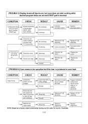
... cooking. 10. Each indicator light does not turn on after setting cooking cycle. 11. Random programming when touching other pads. 5. Replace key membrane assembly and check operation. Replace PCB assembly. 5-13 Beep sound is not heard when correct key is finished. 12. No continuity. REMEDY Replace PCB assembly. Replace key membrane assembly. Display indicates a number different from one or more digits in display. 4. Display time of one touched. 4. Display is touched. 7. RESULT Continuity. Everything works as specified. (TROUBLE...
... cooking. 10. Each indicator light does not turn on after setting cooking cycle. 11. Random programming when touching other pads. 5. Replace key membrane assembly and check operation. Replace PCB assembly. 5-13 Beep sound is not heard when correct key is finished. 12. No continuity. REMEDY Replace PCB assembly. Replace key membrane assembly. Display indicates a number different from one or more digits in display. 4. Display time of one touched. 4. Display is touched. 7. RESULT Continuity. Everything works as specified. (TROUBLE...
Service Manual
Page 25
.... Defective fan motor. CAUSE Decrease in oven load. REMEDY Suggest customer contact local electric power utility co. Replace P.C.B assembly. Defective magnetron. CHECK Check continuity of secondary switch (with load. CAUSE Defective secondary switch. Check the connection between connector and P.C.B assembly. 2. Check fan motor. Check oven lamp. Continuity. Connection then tightly. Replace fan motor. (TROUBLE 4) Oven seems to be operation but oven does not start cooking while desired program times are set and START pad is touched. Disconnect the wire leads...
.... Defective fan motor. CAUSE Decrease in oven load. REMEDY Suggest customer contact local electric power utility co. Replace P.C.B assembly. Defective magnetron. CHECK Check continuity of secondary switch (with load. CAUSE Defective secondary switch. Check the connection between connector and P.C.B assembly. 2. Check fan motor. Check oven lamp. Continuity. Connection then tightly. Replace fan motor. (TROUBLE 4) Oven seems to be operation but oven does not start cooking while desired program times are set and START pad is touched. Disconnect the wire leads...

Owners Manual
Page 3
...A turntable or tray is used to the magnetron tube, is located at the bottom of the oven, but they can penetrate such materials as they travel through the atmosphere and disappear without effect. These microwaves enter the cooking area through metal walls of the oven. Microwaves cannot pass through openings inside the oven. Microwave energy is opened, the oven automatically stops producing microwaves. Precautions Contents Unpacking & Installing Setting the Clock Child Lock Micro Power Cooking Micro Power Level Quick Start Grill Cooking Combination Cooking Auto Cook Auto Defrost Quick...
...A turntable or tray is used to the magnetron tube, is located at the bottom of the oven, but they can penetrate such materials as they travel through the atmosphere and disappear without effect. These microwaves enter the cooking area through metal walls of the oven. Microwaves cannot pass through openings inside the oven. Microwave energy is opened, the oven automatically stops producing microwaves. Precautions Contents Unpacking & Installing Setting the Clock Child Lock Micro Power Cooking Micro Power Level Quick Start Grill Cooking Combination Cooking Auto Cook Auto Defrost Quick...

Owners Manual
Page 5
... a microwave safe container with 300 ml (1/2 pint) of cooking time. The DISPLAY will hear a BEEP each time you have finished the sixth press; YOUR OVEN IS NOW INSTALLED 5 Make sure your oven door by pulling the DOOR HANDLE. Place the ROTATING RING inside the oven and place the GLASS TRAY on the GLASS TRAY and close the oven door. If you press the button. Press the START button six times to set 3 minutes of water. Open...
... a microwave safe container with 300 ml (1/2 pint) of cooking time. The DISPLAY will hear a BEEP each time you have finished the sixth press; YOUR OVEN IS NOW INSTALLED 5 Make sure your oven door by pulling the DOOR HANDLE. Place the ROTATING RING inside the oven and place the GLASS TRAY on the GLASS TRAY and close the oven door. If you press the button. Press the START button six times to set 3 minutes of water. Open...
Owners Manual
Page 7
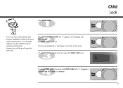
... open the oven door. The time will disappear on the display if you know that prevents accidental running of the oven. You will be unable to let you have set . Once the child lock is now set the clock. weight / time Auto Cook clock Defrost 1 Meat 2 Poultry 3 Fish 4 Bread Quick Defrost To cancel CHILD LOCK press and hold STOP/CLEAR until "L" disappears. "L" remains on the display and BEEP sounds. weight / time clock Defrost 1 Meat 2 Poultry 3 Fish 4 Bread Quick Defrost weight / time 7 clock Defrost Manual Coo1kMeat 2 Poultry Child...
... open the oven door. The time will disappear on the display if you know that prevents accidental running of the oven. You will be unable to let you have set . Once the child lock is now set the clock. weight / time Auto Cook clock Defrost 1 Meat 2 Poultry 3 Fish 4 Bread Quick Defrost To cancel CHILD LOCK press and hold STOP/CLEAR until "L" disappears. "L" remains on the display and BEEP sounds. weight / time clock Defrost 1 Meat 2 Poultry 3 Fish 4 Bread Quick Defrost weight / time 7 clock Defrost Manual Coo1kMeat 2 Poultry Child...
Owners Manual
Page 12
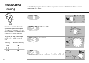
... 3 weight / time clock Defrost 1 Meat 2 Poultry 3 Fish 4 Bread Quick Defrost Be careful when removing your food. This generally means it takes less time to cook your food because the container will show you to cook food with mQiucriockpoDweefrr2o0s%t and combi for a cooking time of micro power level(20%, 40% and 60%) in combi mode. Turn DIAL until display shows "25:00". Category Co-1 Co-2 Co-3 Microwave Power(%) 20 40 60 Press START. Auto Cook Manual Cook Press STOP/CLEAR. weight / time Your oven has a combination cooking...
... 3 weight / time clock Defrost 1 Meat 2 Poultry 3 Fish 4 Bread Quick Defrost Be careful when removing your food. This generally means it takes less time to cook your food because the container will show you to cook food with mQiucriockpoDweefrr2o0s%t and combi for a cooking time of micro power level(20%, 40% and 60%) in combi mode. Turn DIAL until display shows "25:00". Category Co-1 Co-2 Co-3 Microwave Power(%) 20 40 60 Press START. Auto Cook Manual Cook Press STOP/CLEAR. weight / time Your oven has a combination cooking...

Owners Manual
Page 22
... just after cooking. They may heat-up inside the egg which may cause sparks and/or fires when used in cooking. 9 Do not rinse the turntable by a qualified service technician. 17 If smoke is observed, switch off or disconnect the oven from food before use. 23 Do not touch the oven door, outer cabinet, rear cabinet, oven cavity, accessories and dishes during grill mode and auto cook operations, unless wearing thick oven gloves, as...
... just after cooking. They may heat-up inside the egg which may cause sparks and/or fires when used in cooking. 9 Do not rinse the turntable by a qualified service technician. 17 If smoke is observed, switch off or disconnect the oven from food before use. 23 Do not touch the oven door, outer cabinet, rear cabinet, oven cavity, accessories and dishes during grill mode and auto cook operations, unless wearing thick oven gloves, as...


